PT-50LC13/PT-60LC13
LSQT0747 A
Multimedia Projection Display
Operating Instructions
For assistance, please call :
1-888-VIEW PTV(843-9788)
or send e-mail to :
or visit us at www.panasonic.com
(USA)
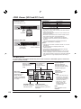
Three Important Reasons to Register Your
Product Immediately!
1 Protect Your New Investment...
Register your new projection display for insurance purposes
in case your new projection display is stolen.
2 Product safety notifi cation...
Registering your product can help us to contact you in the
unlikely event a safety notifi cation is required under the
Consumer Product Safety Act.
3 Improved Product Development...
Help us continue to design products that meet your needs.
Register online at www.panasonic.com/register
For assistance, please call :
787-750-4300
or visit us at www.panasonic.com
(Puerto Rico)
Models No.
As an ENERGY STAR
®
Partner, Matsushita Electric Corporation
of America has determined that this product or product model
meets the
ENERGY STAR
®
guidelines for energy effi ciency.
Before connecting, operating or adjusting this product, please read the instructions completely.
Please keep this manual for future reference.
This operating instruction book is designed for use with models PT-50LC13 and PT-60LC13. Illustrations in this
manual show the PT-50LC13.
2
For assistance, please call : 1-888-VIEW PTV(843-9788)
1) Read these instructions before using, connecting or adjusting this product.
2) Keep these instructions for future reference.
3) Heed all warnings on the product and in this Operating Instructions manual.
4) Follow all instructions carefully.
5) Do not use this product near water. For example, near a bathtub, washbowl, kitchen sink, or laundry tub, in
a wet basement or near a swimming pool, and the like. Do not place objects fi lled with water, such as a vase or
the like, on top of this unit.
6) Clean only with a dry cloth. Do not use liquid cleaners or aerosol cleaners.
7) Do not block any ventilation openings. Install in accordance with the manufacturer’s instructions.
Openings in the cabinet are provided for ventilation to ensure reliable operation and to protect it from
overheating. Never block openings by placing the product on a bed, sofa or similar surfaces.
8) Do not install near any heat source such as radiators, heat registers, stoves, or other apparatus
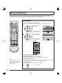
(including amplifi ers) that produces heat. Do not install in a built-in installation such as a bookcase or rack,
unless proper ventilation is provided or the manufacturer’s instructions have bee adhered to.
9) Do not defeat the safety purpose of the polarized or grounding-type plug. A polarized plug has two
blades with one wider than the other. A grounding type plug has two blades and a third grounding
prong. The wide blade or the third prong are provided for your safety. If the provided plug does not fi t
into your outlet, consult an electrician for replacement of the obsolete outlet.
10) Protect the power cord from being walked on or pinched particularly at plugs, convenience receptacles,
and the point where they exit from the apparatus.
11) Use only attachments/accessories specifi ed by the manufacturer.
12) Use only with the cart, stand, tripod, bracket, or table specifi ed by the manufacturer, or
sold with the apparatus. When a cart is used, use caution when moving the cart/apparatus
combination to avoid injury from tip-over.
13) Unplug this apparatus during lightning storms or when unused for long periods of time.
14) Refer all servicing to qualifi ed personnel. Servicing is required when the apparatus has been damaged
in any way, such as power-supply cord or plug is damaged, liquid has been spilled or objects have
fallen into the apparatus, the apparatus has been exposed to rain or moisture, does not operate
normally, or has been dropped.
15) Because the temperature of the lamp unit is elevated immediately after its use, a direct touch to it may cause
burns. Replace the lamp unit only after it has cooled.
Note to CATV System Installer:
This reminder is provided to call the CATV system installer’s attention to Article 820-40 of the NEC that provides
guidelines for proper grounding and, in particular, specifi es that the cable ground shall be connected to the grounding
system of the building, as close to the point of cable entry as practical.
WARNING: To reduce the risk of electric shock, do not remove cover or back. No
user-serviceable parts inside. Refer servicing to qualified service personnel.
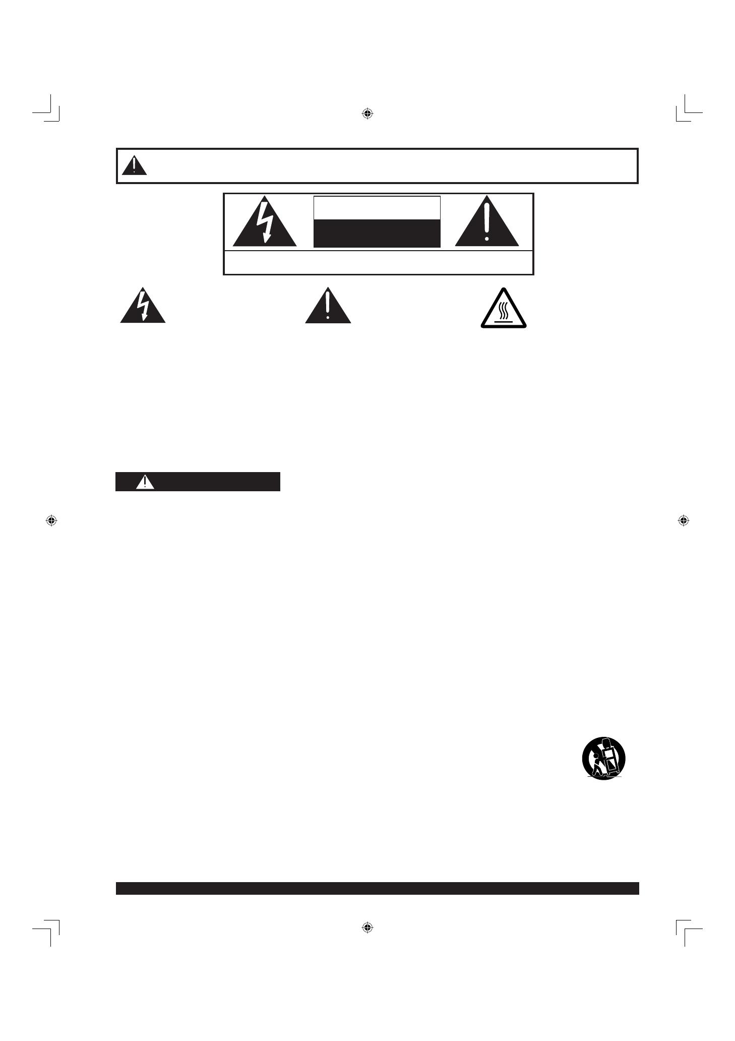
CAUTION
RISK OF ELECTRIC SHOCK
DO NOT OPEN
IMPORTANT SAFETY INSTRUCTIONS
This symbol warns the user
that uninsulated voltage
within the unit may have
suffi cient magnitude to
cause electric shock.
Therefore, it is dangerous
to make any kind of contact
with any inside part of this
unit.
This symbol alerts the
user that important
literature concerning
the operation and
maintenance of this unit
has been included.
Therefore, it should be
read carefully in order to
avoid any problems.
The pictorial
representation of a hot
surface within a triangle
is intended to tell the
user that parts inside
the product are a risk of
burns to persons.
WARNING
- To reduce the risk of electric shock, fi re, injury to persons or damage to this product:

3
Getting Start ed
The lamp has a maximum life of about 10 000 hours.
If use exceeds this fi gure, the possibility of lamp damage becomes greater.
The lamp should be changed as soon as possible once the lamp warning message appears.
If the lamp is damaged, please contact your nearest dealer.
Due to the characteristics and use conditions of in di vid u al lamps, the lamp may cease to light before the
stated lamp life.
Infl uences of fre quent light ing, continuous light use for over 24 hours, the number of times lit, the length of
time between lightings, etc. may shorten lamp life.
(Because of this, we recommend having a replacement lamp on hand.)
Manufactured under license from BBE Sound, Inc.
Licensed by BBE Sound, Inc. under USP4638258 and 4482866.
BBE and BBE symbol are registered trademarks of BBE Sound, Inc.
Trademarks
• VGA and XGA are trademarks of International Business Machines Corporation.
• Macintosh is a registered trademark of Apple Computer, USA.
• VESA and SVGA are trademarks of the Video Electronics Standard Association.
Even if no special notation has been made of company or product trademarks, these trademarks have been fully respected.
• Equipped with -TV Noise Reduction for true MTS reproduction. -TV Noise Reduction is required for good stereo
separation and audio fi delity. is a registered trademark, and is licensed by Technology Licensing.
WARNING
AS WITH ANY SMALL OBJECT, SD CARDS CAN BE SWALLOWED BY YOUNG CHILDREN. DO NOT ALLOW
CHILDREN TO HANDLE THE SD CARD.
(1) This projection display is intended to be used with the following TV stand: model TY-50LC13C for the
PT-50LC13/PT-60LC13. Use with other stands may result in the projection display becoming unstable, possibly
causing injury.
(2) This projection display should not be exposed to direct sunlight, extreme temperatures or moisture, as this can
result in serious irreparable damage.
(3) This product has a High Intensity Discharge (HID) lamp that contains a small amount of mercury. It also contains
lead in some components.
Disposal of these materials may be regulated in your community due to environmental considerations.
For disposal or recycling information please contact your local authorities, or the Electronics Industries Alliance:
<http://www.eiae.org.
>
CAUTION
IMPORTANT SAFETY INSTRUCTIONS (CONTINUED)
4
For assistance, please call : 1-888-VIEW PTV(843-9788)
Welcome to the Panasonic family of customers. We hope that you will have many years of enjoyment from your new
projection display.
To obtain maximum benefi t from your set, please read these Instructions before making any adjustments, and retain
them for future reference.
Retain your purchase receipt also, and record the serial number of your set in the space provided on the rear cover
of these instructions.
Visit our Panasonic Web Site for USA : www.panasonic.com
FCC STATEMENT:
NOTE:
This equipment has been tested and found to comply with the limits for a Class B digital device, pursuant to Part 15
of the FCC Rules. These limits are designed to provide reasonable protection against harmful interference in a
residential installation. This equipment generates, uses and can radiate radio frequency energy and, if not installed
and used in accordance with the instructions, may cause harmful interference to radio communications. However,
there is no guarantee that interference will not occur in a particular installation. If this equipment does cause harmful
interference to radio or television reception, which can be determined by turning the equipment off and on, the user
is encouraged to try to correct the interference by one or more of the following measures:
• Reorient or relocate the receiving antenna.
• Increase the separation between the equipment and receiver.
• Connect the equipment into an outlet on a circuit different from that to which the receiver is connected.
• Consult the dealer or an experienced radio / TV technician for help.
FCC CAUTION:
To assure continued compliance and prevent undesirable interference, use only the provided shielded RGB
cable/DVI cable with 2 ferrite cores while connecting the projection display to a computer. Any changes or
modifi cations not ex press ly approved by the party responsible for compliance could void the user’s authority to
operate this equipment.
For assistance, please call : 1-888-VIEW PTV(843-9788)
or send e-mail to : [email protected]
or visit us at www.panasonic.com
(USA)
For assistance, please call : 787-750-4300
or visit us at www.panasonic.com
(Puerto Rico)
Dear Panasonic Customer
Declaration of Conformity
Models Number: PT-50LC13/PT-60LC13
Trade Name: Panasonic
Responsible party: Matsushita Electric Corporation of America.
Address: One Panasonic Way Secaucus New Jersey 07094
Telephone number: 1-888-VIEW PTV(843-9788)
This device complies with Part 15 of the FCC Rules. Operation is subject to the following two conditions: (1) This
device may not cause harmful interference, and (2) this device must accept any interference received, including
interference that may cause undesired operation.

5
Getting Start ed
To
Start !
Use
Now !
Enjoy
More !
Other
Information !
Getting Start ed
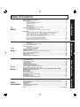
Table of Contents
Basic Operation Advanced Op er a tion Information
Important Safety Instructions.......................................................................................... 2
Before Using ..................................................................................................................... 6
Receiver Location .................................................................................................... 6
Optional External Equipment ................................................................................... 6
Safety Precaution..................................................................................................... 6
Viewing position ....................................................................................................... 6
Accessories.............................................................................................................. 7
Remote Control Battery Installation ......................................................................... 7
Location of Controls ........................................................................................................ 8
Illuminated Remote Control...................................................................................... 8
Controls and Terminals on the projection display .................................................. 10
Installation....................................................................................................................... 12
Connecting the Antenna / Cable to the RF in Terminal (No VCR) ......................... 12
Connecting the Antenna / Cable to the RF in Terminal (VCR)............................... 14
How to connect the “1, 2, 3” Input Terminals ......................................................... 15
How to connect the COMPONENT VIDEO Input Terminals.................................. 16
How to connect the AV Out Terminals ....................................................................17
How to connect the RGB IN Terminals .................................................................. 18
How to connect the DIGITAL IN Terminal .............................................................. 20
RGB/DIGITAL IN signals that can be input............................................................ 21
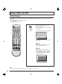
Power ON and OFF......................................................................................................... 22
Initial Setup ............................................................................................................ 22
Turning the Power ON and OFF ............................................................................ 23
Flow Chart of Main menu............................................................................................... 24
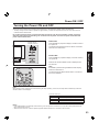
Tuning channels ............................................................................................................. 26
Automatic channel setting ...................................................................................... 26
Manual channel setting .......................................................................................... 28
Projection display operation ......................................................................................... 30
ASPECT Controls ........................................................................................................... 32
Searching for the desired channel (Channel search) ................................................. 34
Playing peripheral equipment ....................................................................................... 35
Mute / Freeze / SAP ........................................................................................................ 36
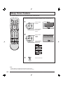
Split screen ..................................................................................................................... 38
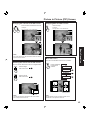
Picture in Picture (PIP) Screen...................................................................................... 40
Adjusting screen position and size .............................................................................. 42
Audio Adjustments......................................................................................................... 44
Picture Adjustments....................................................................................................... 46
Lock Feature ................................................................................................................... 48
Closed Captions ............................................................................................................. 52
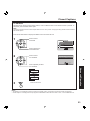
Channel Caption Feature............................................................................................... 54
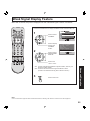
Weak Signal Display Feature......................................................................................... 55
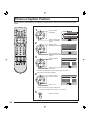
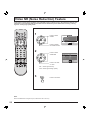
Video NR (Noise Reduction) Feature............................................................................ 56
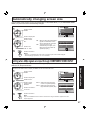
Automatically changing screen size ............................................................................ 57
Setting when 480p signals are input through COMPONENT VIDEO INPUT ............. 57
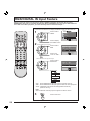
RGB/DIGITAL IN Input Feature...................................................................................... 58
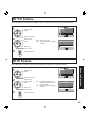
3D Y/C Feature ................................................................................................................ 59
3D IP Feature...................................................................................................................59
Sleep Timer Feature ....................................................................................................... 60
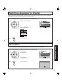
Switching languages for display................................................................................... 61
Information...................................................................................................................... 61
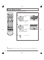
Demo Mode Feature ....................................................................................................... 62
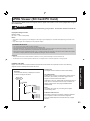
JPEG Viewer (SD Card/PC Card)................................................................................... 63
Replacing the lamp unit................................................................................................. 68
Remote Control Quick Reference Guide (Operating peripheral equipment)............ 69
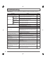
Troubleshooting ............................................................................................................. 76
Specifi cations ................................................................................................................. 77
Cleaning .......................................................................................................................... 78
Customer Services Directory ........................................................................................ 78
Limited Warranty ............................................................................................................ 79
Index ................................................................................................................. Back cover
6
For assistance, please call : 1-888-VIEW PTV(843-9788)
Receiver Location
This projection display is intended to be used with an optional stand or entertainment center. Consult your dealer for
available options.
Locate for comfortable viewing. Avoid placing where sunlight or other bright light (including refl ections) will fall on the
screen.
Use of some types of fl uorescent lighting can reduce remote control transmitter range.
Adequate ventilation is essential to prevent internal component failure. Keep away from areas of excessive heat or
moisture.
Optional External Equipment
The Video / Audio connection between components can be made with shielded video and audio cables. For best
performance, video cables should utilize 75 Ω coaxial shielded cables. Cables are available from your dealer or
electronic supply house.
Before you purchase any cables, be sure you know what type of output and input connectors your various
com po nents require. Also determine the length of cable you’ll need.
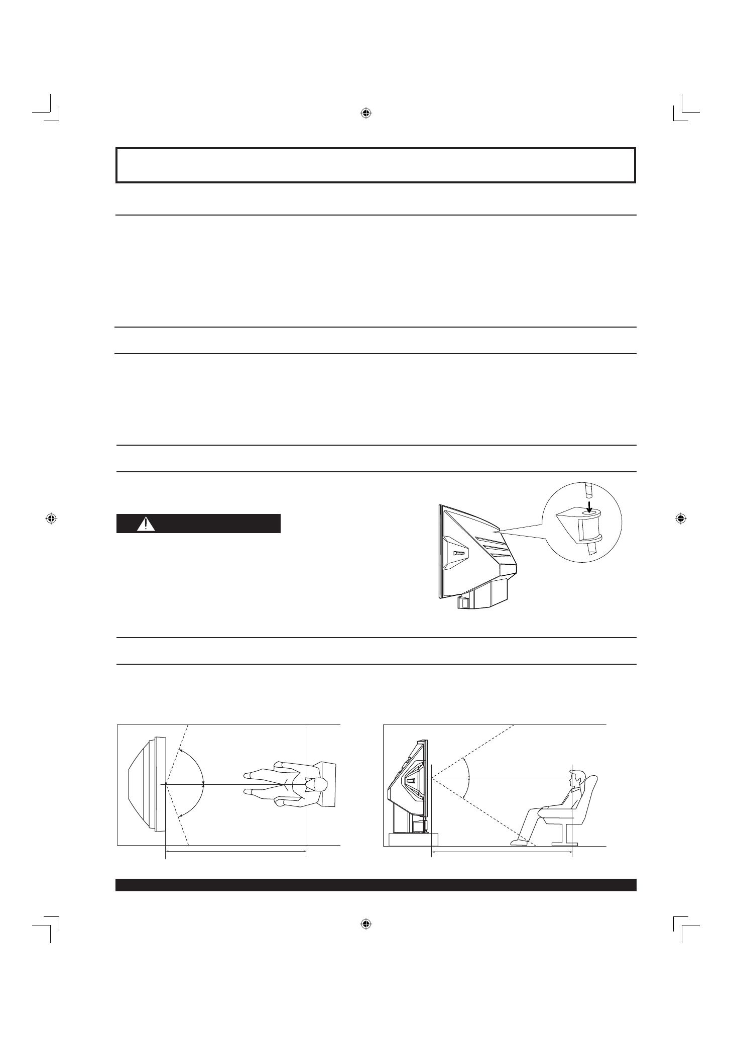
Safety Precaution
Please take safety precautions to prevent the unit from
falling over.
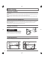
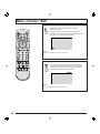
Viewing position
<Side view><Top view>
To optimize your viewing comfort, please follow the viewing guidelines shown in the diagrams below.
If viewing for an extended period of time, sit as far back from the screen as possible.
30º
30º
70º
70º
Before Using
WARNING
The unit may tip or fall if not situated on a stable
surface, if pushed or during an earthquake. Use a
strong rope or chain (not included) to fasten the
projection display fi rmly to a strong wall support.
At least 1.8 m (PT-50LC13)/2.2 m (PT-60LC13). At least 1.8 m (PT-50LC13)/2.2 m (PT-60LC13).

7
Getting Start ed
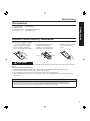
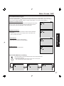
Accessories
Requires two AA batteries (supplied).
1. Turn the Transmitter face down.
Remove top cover by pressing
down on marking and sliding
cover off in the direction indicated.
2. Install the batteries as shown in
the battery compartment.
(Polarity + or - must match the
markings in the compartment).
3. Replace the cover and slide
in reverse until the lock
snaps.
Incorrect battery installation can cause the batteries to leak, leading to personal injury and/or damage to the remote
control.
Observe the following precautions:
1. Batteries should always be replaced as a pair. Always use new batteries when replacing the old set.
2. Do not mix battery types (example: “Zinc Carbon” with “Alkaline”).
3. Do not attempt to charge, short-circuit, disassemble, heat or burn used batteries.
4. Battery replacement is necessary when the remote control acts sporadically or stops operating the projection
display set.
Two AA size
Remote Control Battery Installation
1. Remote Control (EUR7603ZB0)
2. Batteries 2 “AA”
3. RGB Cable (2 m) (LSJA0239-1 or LSJA0443)
4. DVI Cable (2 m) (K1HA24DA0003)
Before Using
Helpful Hints:
(1) For frequent remote control users, replace old batteries with Alkaline batteries for longer battery life.
(2) Whenever you remove the batteries, you may need to reset the remote control infrared codes. We
rec om mend that you record the code on page 70, prior to setting up the remote.
CAUTION

8
For assistance, please call : 1-888-VIEW PTV(843-9788)
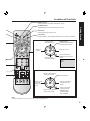
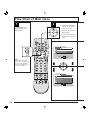
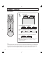
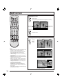
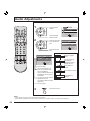
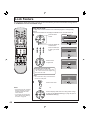
Number keys
When 6 is pressed, channel 6 is dis played in single screen. (P. 31)
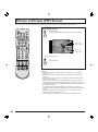
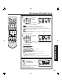
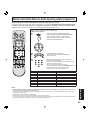
Illuminated Remote Control
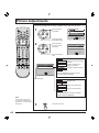
POWER button
Press to turn the projection display ON or OFF. (P. 22)
MUTE button
Press this button to mute the sound. (P. 36)
Mode Selection buttons
Selects the operation mode for the remote control. (PP. 69-75)
R-TUNE button
Press to view previous channel or video mode.
Function buttons
Location of Controls
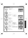
PIP MIN
(P. 41)
SD
(P. 35)
PIP MAX
(P. 41)
FREEZE
(P. 36)
PIP/SPLIT CH
Down
(PP. 39, 41)
PIP/SPLIT CH
Up
(PP. 39, 41)
CH Search
(P. 34)
PIP
(P. 40)
SPLIT
(P. 38)
PIP MOVE
(P. 41)
PIP/SPLIT
SWAP
(PP. 39, 41)
DVD (Digital Versatile
Disc) Mode Selection for
Remote Control
VCR Mode Selection for
Remote Control
TV Mode Selection for
Remote Control
Digital TV Mode Selection
for Remote Control
AUX Mode Selection
for Remote Control
Receiver / Amplifi er Mode
Selection for Remote Control
Cable TV Mode Selection for
Remote Control
Digital Broadcasting Satellite for
Remote Control
PC/MENU button
RGB input mode is displayed.
Toggles between RGB1 and RGB2 input mode. (P. 35)

9
Getting Start ed
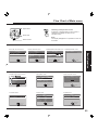
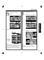
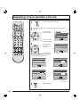
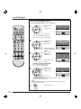
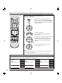
ASPECT button
Changes the way the image is displayed. (P. 32)
Light button
Lights all buttons. The selected mode button (TV, VCR, etc.) fl ashes.
TV/VIDEO button
Toggles between TV and VIDEO inputs. (P. 35)
Reduces
volume.
Changes to the
next channel up.
Increase volume.
The screen below is
displayed for 5 seconds.
(P. 31)
Changes to the
next channel down.
Returns to normal
viewing from the
MENU screen.
Previous before
item in MENU.
SAP button
Changes the audio mode. (P. 37)
Display menu
Press the ACTION button
to display Menu screen.
Note:
This section describes TV mode only. For other modes, see pages 69-75.
21HC
CBA
LAMRON
OERETS
PAS
ONOM
When the Menu screen is displayed, (PP. 24-25)
Moves cursor
to the left
during menu
mode.
Moves cursor upward
during menu mode.
Moves cursor down ward
during menu mode.
Moves cursor to the
right during menu
mode.
Sets the items.
Location of Controls

10
For assistance, please call : 1-888-VIEW PTV(843-9788)
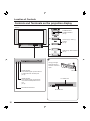
Controls and Terminals on the projection display
< FRONT >
LAMP indicator
This indicator lights up when there is
a malfunction with the lamp unit.
(P. 76)
TEMP indicator
This indicator lights up when there
is an abnormal tem per a ture in the
unit.
(P. 76)
Remote Control Sensor
POWER button/
POWER indicator
(P. 23)
Volume up(+) / down(–)
buttons
(P. 30)
Channel up / down buttons
(P. 31)
Location of Controls
Open
A
A
SD CARD slot
PC CARD slot
Using your fi nger,
slide Slot Cover in
direction of arrow to
open.
Slot Cover
Model PT-50LC13 unit shown
11
Getting Start ed
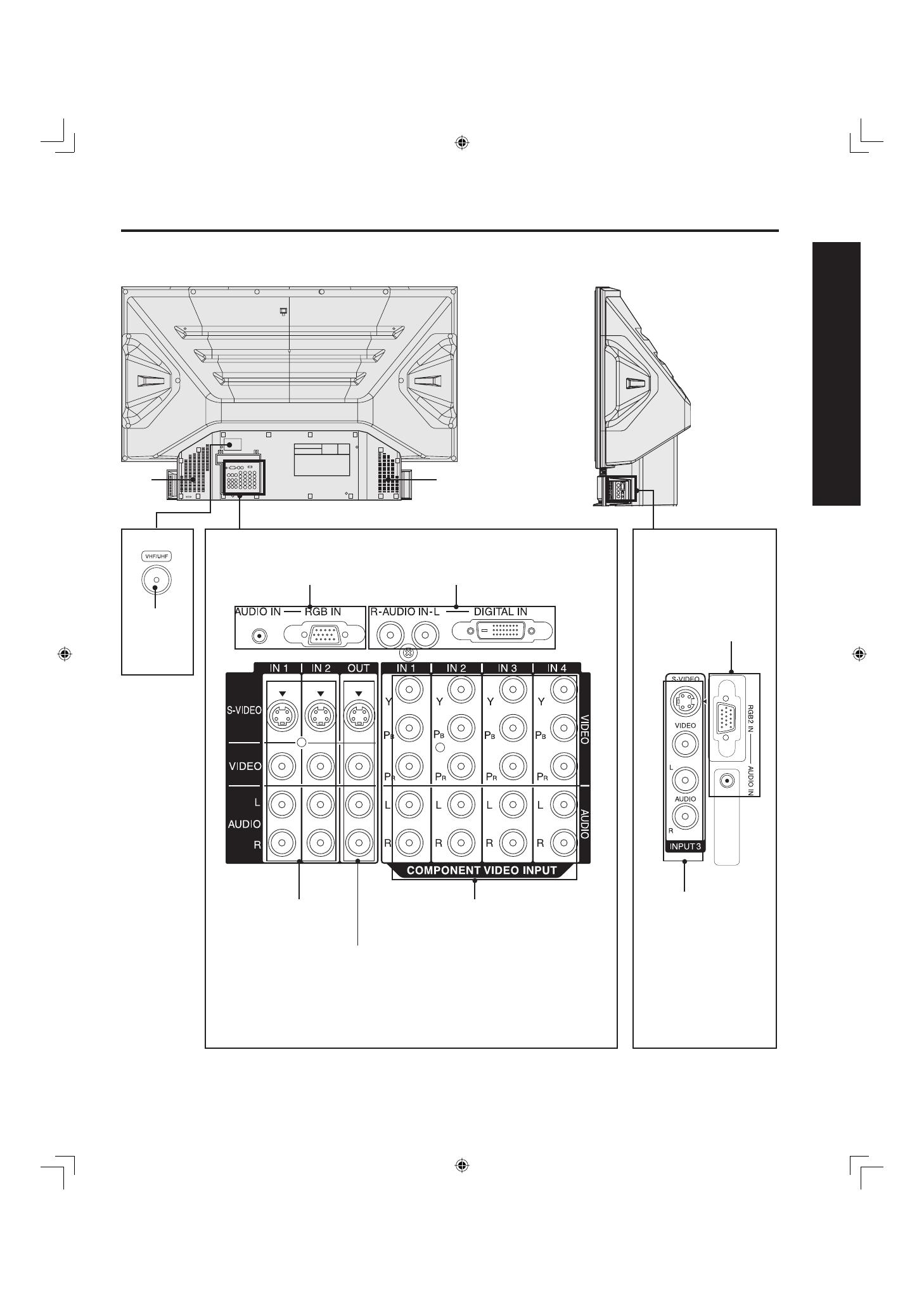
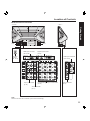
< REAR >
VHF/UHF
terminal
(PP. 12-14)
Vent
Note:
Make sure the vents are not blocked. (This could cause damage.)
Location of Controls
Vent
Component signal input 1-4 ter mi nals
(P. 16)
AV out terminals
(P. 17)
Input 1, 2 ter mi nals
(P. 15)
RGB Input 1 terminal
(PP. 18-19)
Digital Input terminal
(P. 20)
< SIDE >
Input 3 ter mi nals
(P. 15)
RGB Input 2 terminal
(PP. 18-19)
Model PT-50LC13 unit shown
12
For assistance, please call : 1-888-VIEW PTV(843-9788)
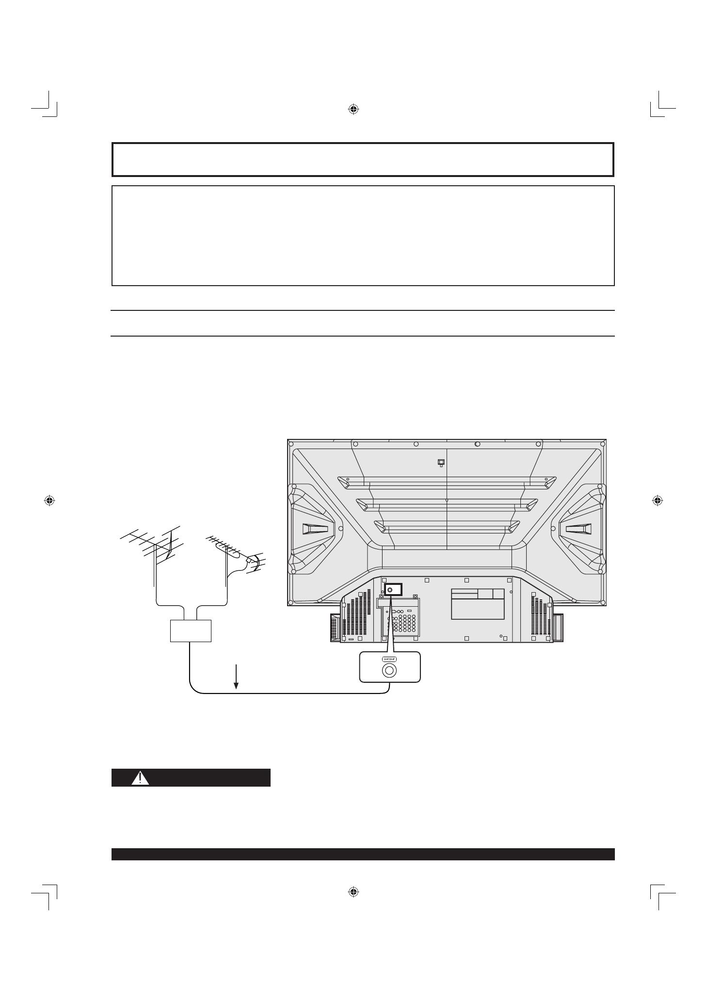
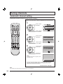
Connecting the Antenna / Cable to the RF in Ter mi nal (No VCR)
Antenna Connection
For proper reception of VHF / UHF channels, an external antenna is required. For best reception an outdoor
antenna is recommended.
When using “Nut type” RF coaxial cables, tighten with fi ngers only. Overtightening may damage terminals.
• Turn off the power supply for all com po nents before making any connections.
• If the cables necessary for connecting a component to the system are not included with the component or available as an
option, you may need to fashion a cable to suit the component concerned.
• Read the instruction manual for each system component care ful ly before connecting it.
• If there is a lot of jitter in the video signal input from the video source, the picture on the screen may fl icker. In this case, it will
be necessary to connect a TBC (time base corrector).
Notes on con nec tions
Installation
VHF/UHF TERMINAL
ON THE BACK OF THE
PROJECTION DISPLAY
RF Coaxial Cable
Mixer
VHF Antenna UHF Antenna
CAUTION
13
Getting Start ed
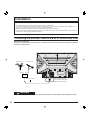
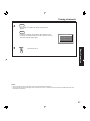
Cable Connection
Use this confi guration when connecting the projection display to a cable TV system.
Notes:
• Certain cable systems offset some channels to reduce interference or have Premium (scrambled) channels. A cable converter
box is required for proper reception. Check with your local Cable company for its compatibility re quire ments.
• For reception of cable channels (01 - 125) connect the cable supplied by your local cable company.
Antenna Mode must be set to CABLE. (P. 26)
Or
Installation
CABLE BOX
TERMINAL ON
THE BACK OF
THE CABLE
BOX
In from cable
Connect the cable from the antenna or
cable system to the VHF/UHF terminal
on the back of the projection display.
In from cable
14
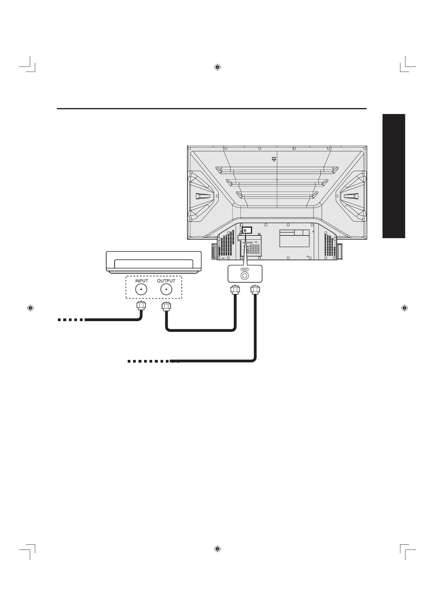
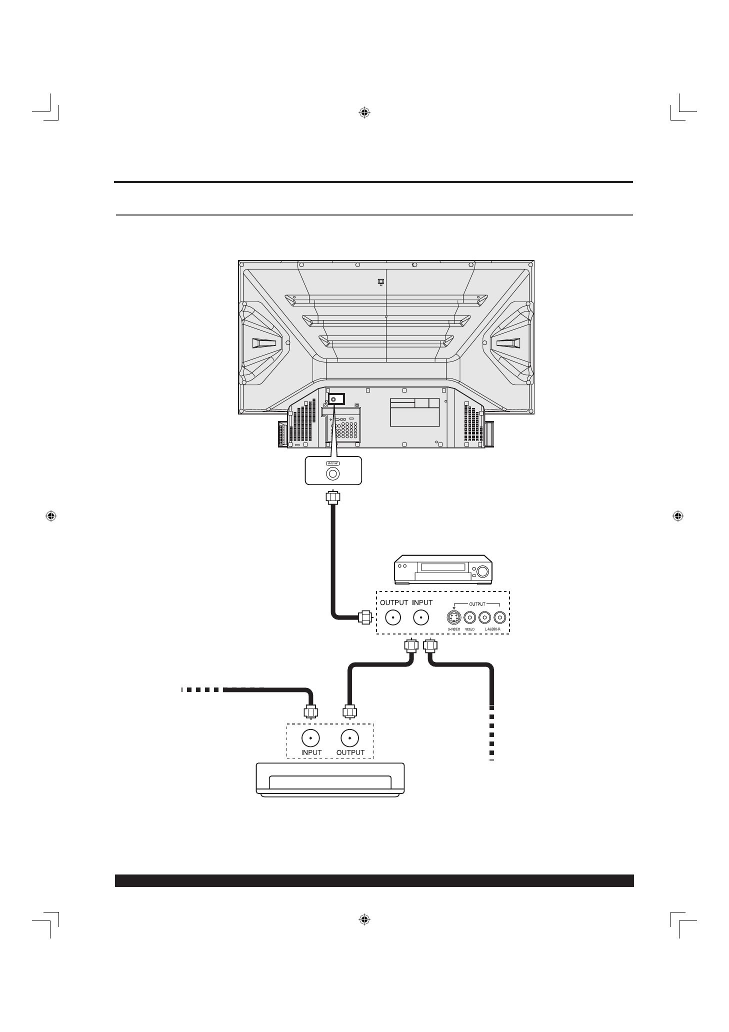
For assistance, please call : 1-888-VIEW PTV(843-9788)
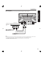
Use this confi guration when connecting the projection display to a cable TV system using VCR.
Note:
When the RF coaxial cable is connected to the projection display VHF/UHF terminal via a cable box or VCR, set the TV channel to
CH3 or CH4. This does not apply when signal is input from VIDEO INPUT.
Connecting the Antenna / Cable to the RF in Ter mi nal (VCR)
Or
Installation
Connect the cable from the Output
terminal on the back of the Cable Box
or antenna/cable system to the Antenna
input terminal on the back of the VCR.
VCR
Incoming Cable
from Antenna or
Cable TV System
↑ TO VCR
In from cable
TERMINAL ON
THE BACK OF
THE CABLE BOX
CABLE BOX
↑ TO VCR
15
Getting Start ed
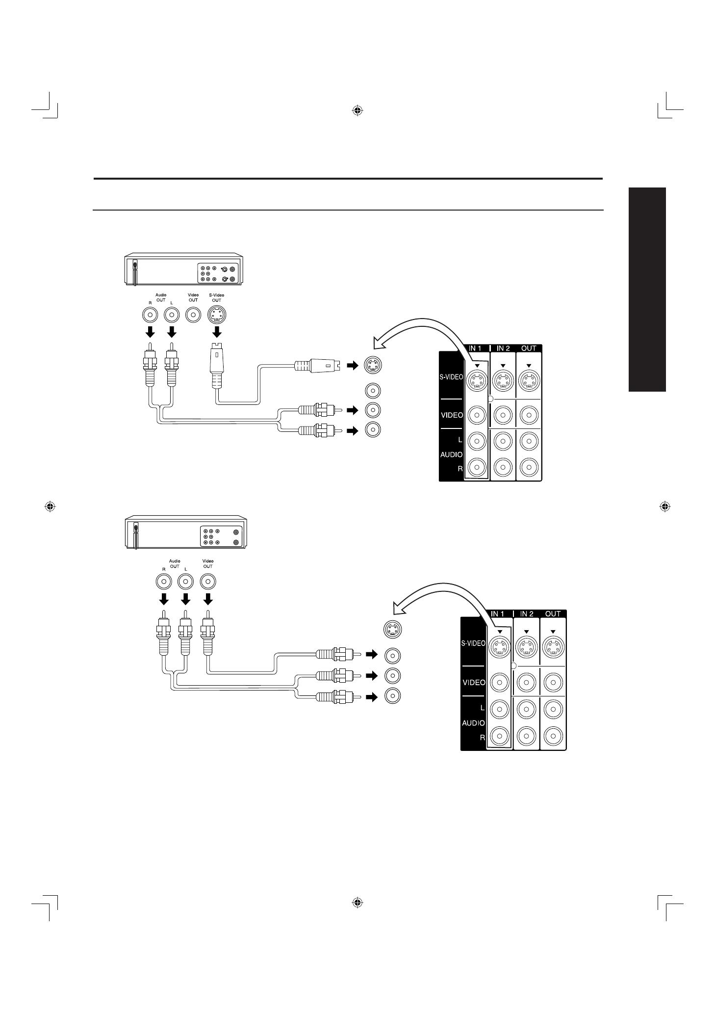
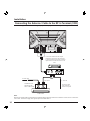
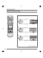
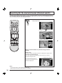
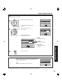
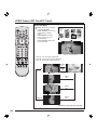
How to connect the “1, 2, 3” Input Ter mi nals
Connects VCRs and other peripheral equipment
Similar connections are available at the INPUT 1, 2, 3 input terminals.
Notes:
• Similar connections are available at the INPUT 1, 2, 3 input terminals.
• Input 3 is located on the side of the unit.
• Select the desired VIDEO input position by pressing the TV/VIDEO button. (P. 35)
• When connecting video cables, priority is given to the S-Video cable when the S-Video input terminal and the video input
terminal are connected at the same time.
Similar connections are available at the INPUT 1, 2, 3 input terminals.
(P. 11)
Installation
(S-VHS VCR)
S-VIDEO
AUDIO
(VHS VCR)
VIDEO
AUDIO
16
For assistance, please call : 1-888-VIEW PTV(843-9788)
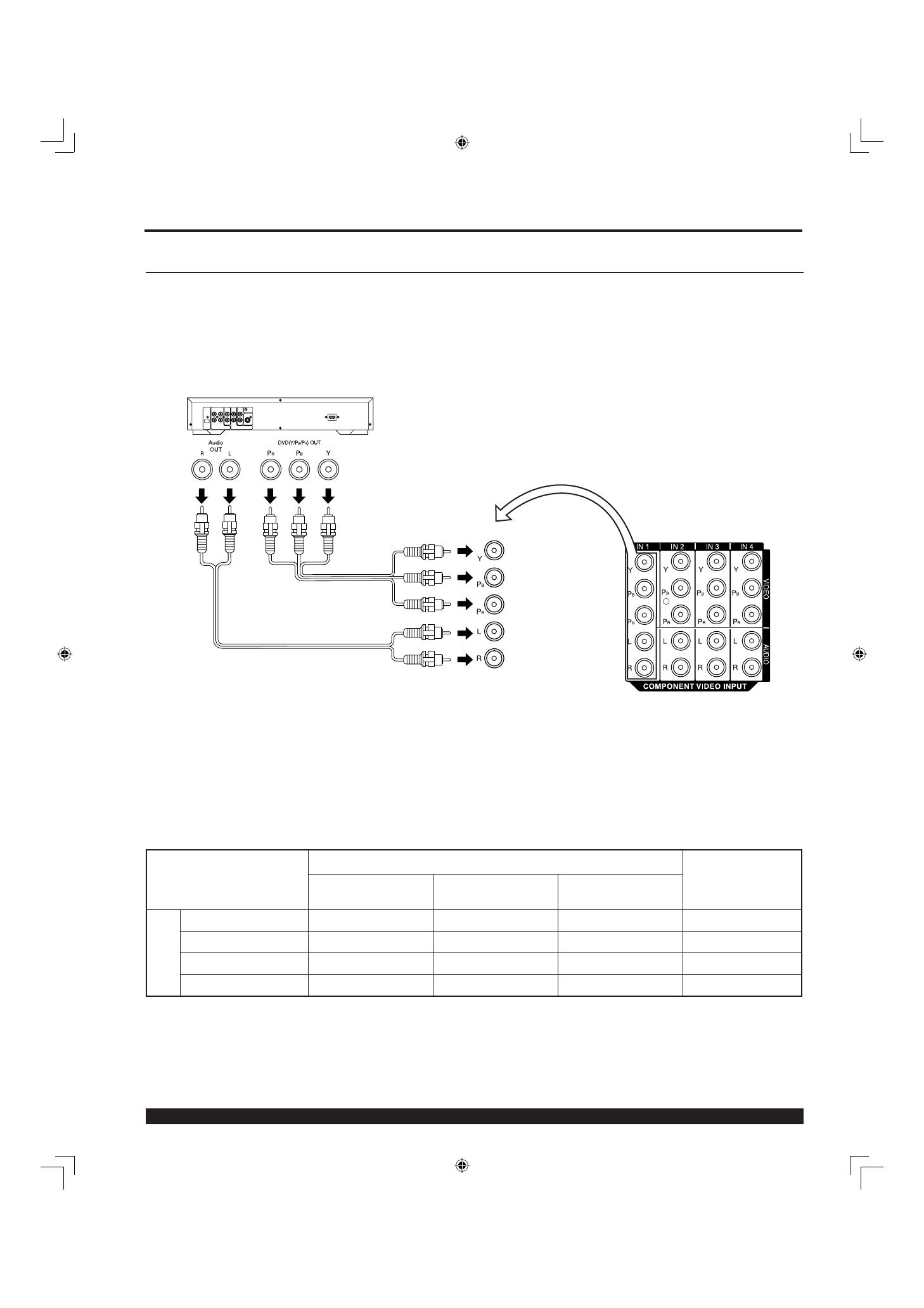
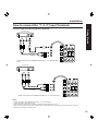
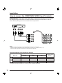
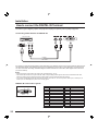
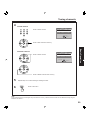
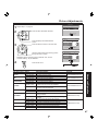
How to con nect the COMPONENT VIDEO Input Ter mi nals
Notes:
• Similar connections are available at the COMPONENT VIDEO INPUT 1-4 Terminals.
• Select the desired COMPONENT VIDEO INPUT position by pressing the TV/VIDEO button. (P. 35)
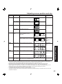
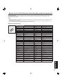
• Component video signals that can be input are 480i, 480p, 720p, and 1080i.
Because each Y, PB, and PR signal is input independently, the Component signal allows for more accurate
color reproduction.
The Component signal output terminal indication will differ according to the output device ( Y, PB, PR).
Please read the operating instructions included with the output device.
Installation
DVD Player
COMPONENT VIDEO
AUDIO
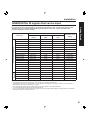
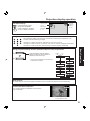
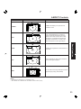
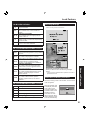
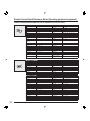
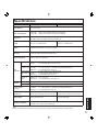
Mode type
Signal data
Information menu
display
No. of dots
(H X V)
Horizontal frequency
(kHz)
Vertical frequency
(Hz)
DTV Format
Signals
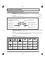
480i 664 X 485 15.73 29.97 480 i
480p 720 X 483 31.47 59.94 480 p
720p 1 280 X 720 45.00 60.00 720 p
*1080i 1 920 X 1 080 33.75 30.00 1080 i
Component Signals (Y, PB, PR) that can be Input
Note:
Input signals, other than those listed with a * mark, will give you a beautiful, stable picture.

17
Getting Start ed
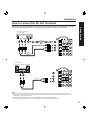
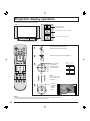
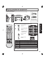
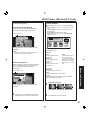
How to connect the AV Out Terminals
The “AV Out” Terminals output the same signals as the main picture on the projection display screen and
sound from the speaker at that time, e.g. TV programs or signals from INPUT 1, 2, 3 terminals.
Notes:
• Never connect the VIDEO IN and OUT terminals to the same video recorder, as this could cause incorrect operation.
• Even if TV is in Split or PIP mode, OUT terminals only output the main picture and sound signals. A sub-picture, including
channel search, etc., will not be output.
• VIDEO OUT terminals will not output Y, P
B, PR, RGB/DIGITAL IN or SD/PC card signals.
• The S-Video OUT terminal outputs the same signal that is input from the S-Video IN terminal.
Or
Installation
Recording Equipment
(S-VHS VCR)
S-VIDEO
VIDEO
AUDIO
Stereo System
(A Stereo Amplifi er and Speakers)
AUDIO
18
For assistance, please call : 1-888-VIEW PTV(843-9788)
RGB OUT AUDIO OUT
COMPUTER
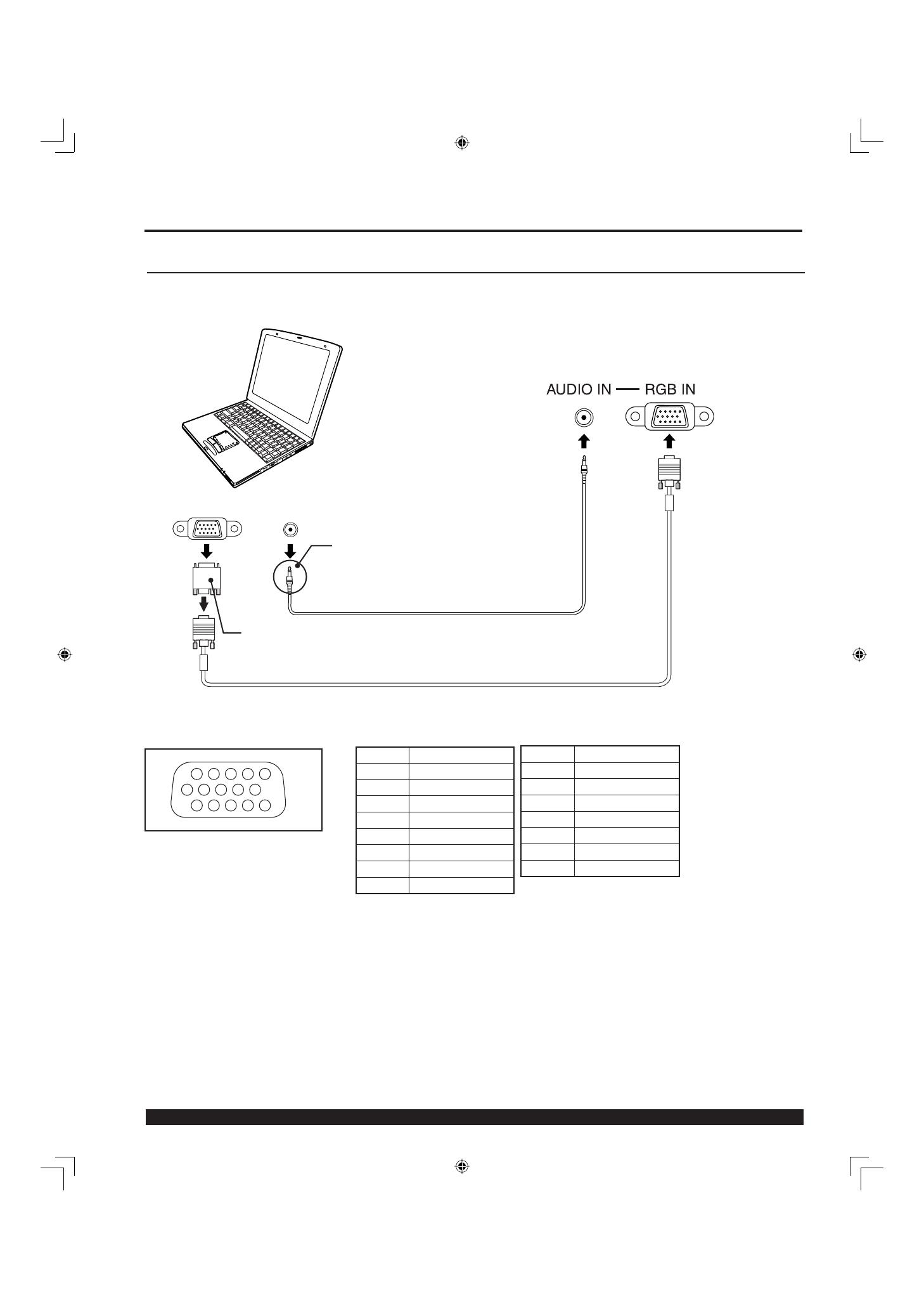
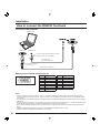
How to connect the RGB IN Terminals
Notes:
• Some PC models cannot be connected to the set. A conversion adapter is required to use the RGB cable (D-SUB 15P) to
connect a Macintosh computer to the set. There is no need to use an adapter for computers with PC / AT compatible D-SUB
15P terminal.
• The computer shown in the illustration is for example purposes only. Additional equipment and cables shown are not supplied
with this set.
• The picture will become dark if an PC signal with a vertical scanning frequency of 62 Hz is input. To obtain the optimum picture
quality with the projection display, a vertical scanning frequency of 60 Hz is recommended.
• Do not set the horizontal and vertical scanning frequencies for PC signals which are above or below the specifi ed frequency
range.
• Select the desired RGB input position by pressing the PC/MENU or TV/VIDEO button. (P. 35)
• Similar connections are available at the RGB IN 1, 2 Terminals.
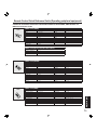
Pin No. Signal name
1R
2G
3B
4NC
5NC
6 Ground for R
7 Ground for G
8 Ground for B
1
678
3
9
45
10
1514131211
2
NC: Not connected
Installation
Pin No. Signal name
9NC
10 Ground
11 NC
12 NC
13 HD/CSYNC
14 VD
15 NC
PC audio cable
(M3 stereo mini pin)
Connect a cable which matches the audio
output terminal on the computer.
Conversion adapter
(If necessary)
RGB cable (D-SUB 15P)
RGB IN Terminal (D-SUB 15P) Pin Layouts
Connection port view
Connecting a PC to RGB IN
19
Getting Start ed
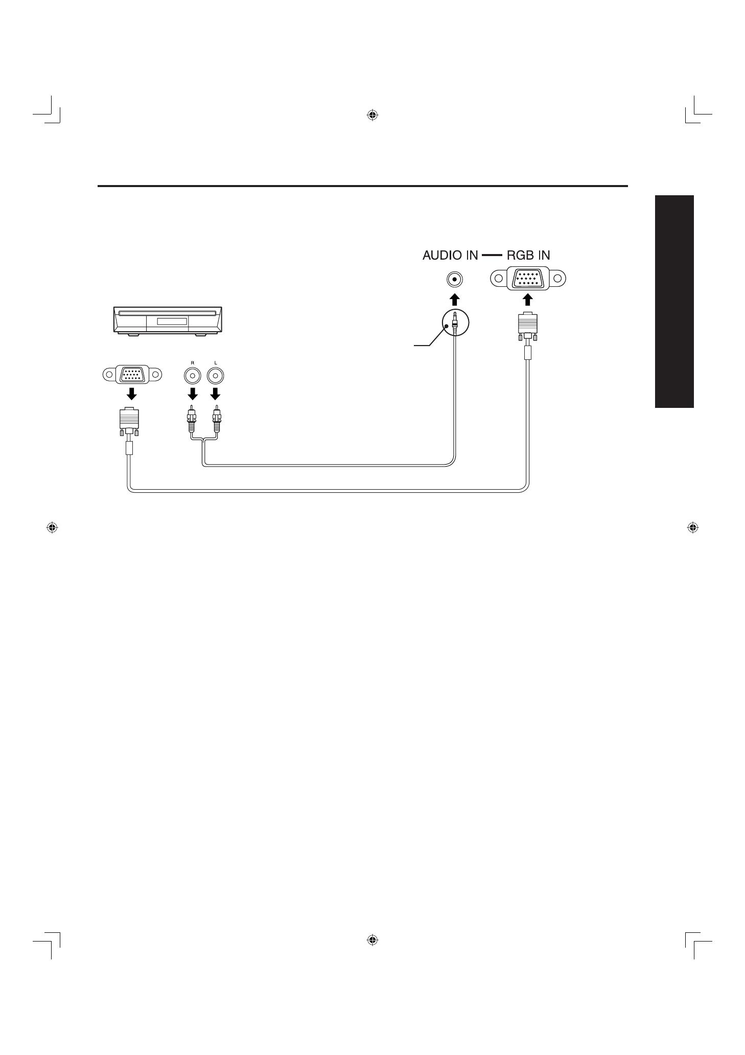
Installation
RGB OUT
AUDIO OUT
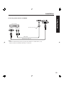
Connecting a DTV Decoder to RGB IN
RGB cable (D-SUB 15P)
Audio cable
Notes:
• Select the desired RGB input position by pressing the PC/MENU or TV/VIDEO button. (P. 35)
• Similar connections are available at the RGB IN 1, 2 Terminals.
M3 stereo mini pin
DTV Decoder
20
For assistance, please call : 1-888-VIEW PTV(843-9788)
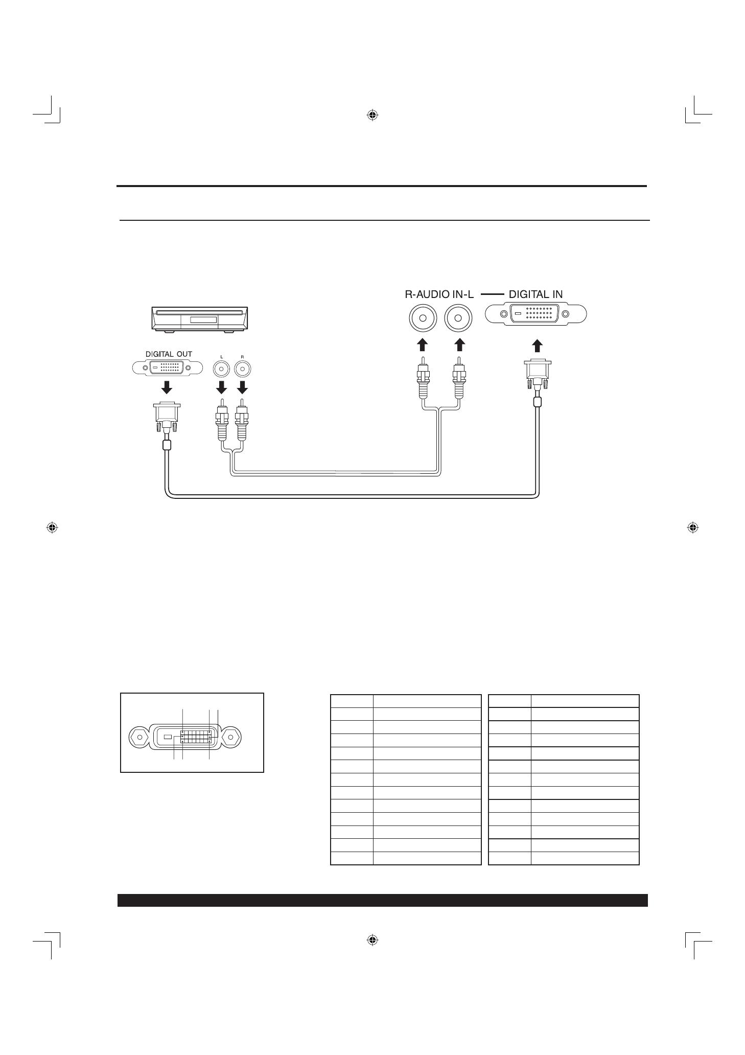
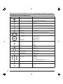
DIGITAL IN Terminal Pin Layouts
Connection port view
8116
17 924
Pin No. Signal name
1T.M.D.S Data 2-
2T.M.D.S Data 2+
3 T.M.D.S Data 2 Shield
4NC
5NC
6DDC Clock
7DDC Data
8NC
9T.M.D.S Data 1-
10 T.M.D.S Data 1+
11 T.M.D.S Data 1 Shield
12 NC
NC: Not connected
Pin No. Signal name
13 NC
14 +5 V
15 GND
16 Hot Plug Detect
17 T.M.D.S Data 0-
18 T.M.D.S Data 0+
19 T.M.D.S Data 0 Shield
20 NC
21 NC
22 T.M.D.S Clock Shield
23 T.M.D.S Clock +
24 T.M.D.S Clock -
AUDIO OUT
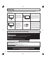
How to connect the DIGITAL IN Terminal
Connecting a DTV Decoder to DIGITAL IN
By inputting a High-bandwidth Digital Content Protection high-defi nition picture source to the DIGITAL IN terminal of
this projection display, high-defi nition pictures can be displayed on the screen in their digital form. (This terminal is
for use in the future when High-bandwidth Digital Content Protection DTV decoders, DVD players and D-VHS are
put on the market.)
DVI cable
Notes:
• Select the DIGITAL input position by pressing the TV/VIDEO button. (P. 35)
• The DIGITAL IN terminal can only be used with 1080i, 720p and 480p picture signals. Set the DTV Decoder DIGITAL OUT
terminal to 1080i, 720p, or 480p signal output. Please refer to the DTV Decoder instruction manual.
• If no picture is displayed because the DTV Decoder output cannot be set, use the component Video Input, S-Video Input, or
Video Input. This will display the picture as an analog signal.
AUDIO
The video signal is digitally input to the projection display for superior picture quality enjoyment.
Installation
DTV Decoder
Page is loading ...
Page is loading ...
Page is loading ...
Page is loading ...
Page is loading ...
Page is loading ...
Page is loading ...
Page is loading ...
Page is loading ...
Page is loading ...
Page is loading ...
Page is loading ...
Page is loading ...
Page is loading ...
Page is loading ...
Page is loading ...
Page is loading ...
Page is loading ...
Page is loading ...
Page is loading ...
Page is loading ...
Page is loading ...
Page is loading ...
Page is loading ...
Page is loading ...
Page is loading ...
Page is loading ...
Page is loading ...
Page is loading ...
Page is loading ...
Page is loading ...
Page is loading ...
Page is loading ...
Page is loading ...
Page is loading ...
Page is loading ...
Page is loading ...
Page is loading ...
Page is loading ...
Page is loading ...
Page is loading ...
Page is loading ...
Page is loading ...
Page is loading ...
Page is loading ...
Page is loading ...
Page is loading ...
Page is loading ...
Page is loading ...
Page is loading ...
Page is loading ...
Page is loading ...
Page is loading ...
Page is loading ...
Page is loading ...
Page is loading ...
Page is loading ...
Page is loading ...
Page is loading ...
Page is loading ...
-
 1
1
-
 2
2
-
 3
3
-
 4
4
-
 5
5
-
 6
6
-
 7
7
-
 8
8
-
 9
9
-
 10
10
-
 11
11
-
 12
12
-
 13
13
-
 14
14
-
 15
15
-
 16
16
-
 17
17
-
 18
18
-
 19
19
-
 20
20
-
 21
21
-
 22
22
-
 23
23
-
 24
24
-
 25
25
-
 26
26
-
 27
27
-
 28
28
-
 29
29
-
 30
30
-
 31
31
-
 32
32
-
 33
33
-
 34
34
-
 35
35
-
 36
36
-
 37
37
-
 38
38
-
 39
39
-
 40
40
-
 41
41
-
 42
42
-
 43
43
-
 44
44
-
 45
45
-
 46
46
-
 47
47
-
 48
48
-
 49
49
-
 50
50
-
 51
51
-
 52
52
-
 53
53
-
 54
54
-
 55
55
-
 56
56
-
 57
57
-
 58
58
-
 59
59
-
 60
60
-
 61
61
-
 62
62
-
 63
63
-
 64
64
-
 65
65
-
 66
66
-
 67
67
-
 68
68
-
 69
69
-
 70
70
-
 71
71
-
 72
72
-
 73
73
-
 74
74
-
 75
75
-
 76
76
-
 77
77
-
 78
78
-
 79
79
-
 80
80


Ask a question and I''ll find the answer in the document
Finding information in a document is now easier with AI
Related papers
-
Panasonic PT40LC12K Operating instructions
-
-
-
-
-
-
-
Philips 27-COLOR TV W-PIP-REMOTE-DBX STEREO 27PS60S User manual
-
-
Other documents
-
Sony KF-60XBR800 User manual
-
-
-
Quasar SP-3235 User manual
-
JVC GD-V4210PZW-G User manual
-
Sanyo PLV-65WHD1 User manual
-
-
Changhong Electric DLP5132 User manual
-
Naxa NAA-305 Owner's manual
-
Hitachi 50C10E User manual