Page is loading ...

© Panasonic Home Appliances Air-Conditioning
(Guangzhou) Co.,Ltd (PHAAG) 2010. All rights
reserved. Unauthorized copying and distribution is a
violation of law.
Order No: PHA-AG1102005C2
Indoor Unit Outdoor Unit
CS-YE9MKX
CS-YE12MKX
CS-YE18MKX
CU-YE9MKX
CU-YE12MKX
CU-YE18MKX
TABLE OF CONTENTS
1. Safety Precautions.............................................3
2. Specification.......................................................5
3. Features ..............................................................9
4. Location of Controls and Components .........10
4.1 Indoor Unit .................................................10
4.2 Outdoor Unit...............................................10
4.3 Remote Control..........................................10
5. Dimensions.......................................................11
5.1 Indoor Unit..................................................11
5.2 Outdoor Unit...............................................12
6. Refrigeration Cycle Diagram...........................13
7. Block Diagram..................................................14
8. Wiring Diagram.................................................15
9. Printed Circuit Board.......................................19
9.1 Indoor Unit..................................................19
9.2 Outdoor Unit...............................................19
10. Installation Instruction.....................................20
10.1 Select the Best Location ............................20
10.2 Indoor Unit..................................................21
10.3 Outdoor Unit...............................................23
11. Service Mode....................................................26
11.1 Auto OFF/ON Button..................................26
11.2 Select Remote Control Transmission Code
26
11.3 Operate and Display of Remote Control....27
12. Operation Control.............................................29
12.1 Basic Function............................................29
12.2 Indoor Fan Motor Operation.......................30
12.3 Outdoor Fan Motor Operation....................30
13. Protection control ............................................33
13.1 Protection Control For All Operations ........33
This service information is designed for experienced repair technicians only and is not designed for use by the general public.
It does not contain warnings or cautions to advise non-technical individuals of potential dangers in attempting to service a product.
Products powered by electricity should be serviced or repaired only by experienced professional technicians. Any attempt to service
or repair the products dealt with in this service information by anyone else could result in serious injury or death.
WARNING

2
13.2
Protection Control For Cooling and Soft Dry
Operation...............................................................35
13.3 Indoor Piping Air Temperature Control
(Heating)................................................................36
14. Troubleshooting Guide....................................38
14.1 Refrigeration cycle system .........................38
14.2 Breakdown Self Diagnosis Function...........39
15. Disassembly and Assembly Instructions ......41
16. Exploded View and Replacement Pars List...44
16.1 Indoor Unit..................................................44
16.2 Outdoor Unit...............................................46

3
CAUTION
WARNING
WARNING
1. Safety Precautions
• Read the following “SAFETY PRECAUTIONS” carefully before perform any servicing.
• Electrical work must be installed or serviced by a licensed electrician. Be sure to use the correct rating of the
power plug and main circuit for the model installed.
• The caution items stated here must be followed because these important contents are related to safety. The
meaning of each indication used is as below. Incorrect installation or servicing due to ignoring of the instruction
will cause harm or damage, and the seriousness is classified by the following indications.
This indication shows the possibility of causing death or serious injury
This indication shows the possibility of causing injury or damage to properties.
• The items to be followed are classified by the symbols:
• Carry out test run to confirm that no abnormality occurs after the servicing. Then, explain to user the operation,
care and maintenance as stated in instructions. Please remind the customer to keep the operating instructions for
future reference.
1. Engage dealer or specialist for installation. If installation done by the user is defective, it will cause water leakage,
electrical shock or fire.
2. Install according to this installation instructions strictly. If installation is defective, it will cause water leakage, electrical
shock or fire.
3. Use the attached accessories parts and specified parts for installation. Otherwise, it will cause the set to fall, water
leakage, fire or electrical shock.
4. Install at a strong and firm location which is able to withstand the set’s weight. If the strength is not enough or
installation is not properly done, the set will drop and cause injury.
5. Do not install outdoor unit near handrail of veranda. When installing air-conditioner unit at veranda of high rise
building, child may climb up to outdoor unit and cross over the handrail and causing accident.
6. For electrical work, follow the local national wiring standard, regulation and this installation instruction. An independent
circuit and single outlet must be used. If electrical circuit capacity is not enough or defect found in electrical work, it will
cause electrical shock or fire.
7. This equipment is strongly recommended to be installed with Earth Leakage Circuit Breaker (ELCB) or Residual
Current Device (RCD). Otherwise, it may cause electrical shock and fire in case equipment breakdown or insulation
breakdown.
8. This equipment must be properly earthed. Earth line must not be connected to gas pipe, water pipe, earth of lightning
rod and telephone. Otherwise, it may cause electrical shock in case equipment breakdown or insulation breakdown.
9. Do not use joint cable for indoor/outdoor connection cable. Use the specified Indoor/Outdoor connection cable, refer to
installation instructions CONNECT THE CABLE TO THE INDOOR UNIT and connect tightly for indoor / outdoor
connection. Clamp the cable so that no external force will be acted on the terminal. If connection or fixing is not
perfect, it will cause heat up or fire at the connection.
10. Wire routing must be properly arranged so that control board cover is fixed properly. If control board cover is not fixed
perfectly, it will cause fire or electrical shock.
11. When install or relocate air conditioner, do not let any substance other than the specified refrigerant , eg. Air etc. mix
into refrigeration cycle (piping) . Mixing of air etc. will cause abnormal high pressure in refrigerant cycle and result in
explosion, injury etc.
12. Do not use unspecified cord, modified cord, joint cord or extension cord for power supply cord. Do not share the single
outlet with other appliances. Poor contact, poor insulation or over current will cause electrical shock or fire.
13. • For R410A models, when connecting the piping, do not use any existing (R22) pipes and flare nuts. Using such
same may cause abnormally high pressure in the refrigeration cycle (piping), and possibly result in explosion and
injury. Use only R410A materials.
• Thickness or copper pipes used with R410A must be more than 0.8 mm. Never use copper pipes thinner than 0.8 mm
• It is desirable that the amount of residual oil is less than 40 mg/10 m.
14. During installation, install the refrigerant piping properly before run the compressor. Operation of compressor without
fixing refrigeration piping and valves at opened condition will cause suck-in of air, abnormal high pressure in
refrigeration cycle and result in explosion, injury etc.
15. During pump down operation, stop the compressor before remove the refrigeration piping. Removal of refrigeration
piping while compressor is operating and valves are opened will cause suck-in of air, abnormal high pressure in
refrigeration cycle and result in explosion, injury etc.
Symbol with white background denotes item that is PROHIBITED from doing.
Symbol with dark background denotes item that must be carried out.

4
CAUTION
16. After completion of installation, confirm there is no leakage of refrigerant gas. It may generate toxic gas when the
refrigerant contacts with fire.
17. Ventilate if there is refrigerant gas leakage during operation. It may cause toxic gas when the refrigerant contacts with
fire.
18. Recommended installation height for indoor unit shall be at least 2.5 m.
19. The appliance shall be installed in accordance with national wiring regulations.
20. Keep plastic bag (package material) away from small children, it may cling to nose and mouth and prevent breathing.
21. Tighten the flare nut with torque wrench according to specified method. If the flare nut is over-tightened,
after a long period, the flare may break and cause refrigerant gas leakage.
22. Do not insert your fingers or other objects into the unit, high speed rotating fan may cause injury.
23. Do not modify the machine, part, material during repairing service.
24. Must not use other parts except original parts describe in catalog and manual.
1. Do not install the unit at place where leakage of flammable gas may occur. In case gas leaks and accumulates at
surrounding of the unit, it may cause fire.
2. Carry out drainage piping as mentioned in installation instructions. If drainage is not perfect, water may enter the room
and damage the furniture.
3. Do not touch outdoor unit air inlet and aluminums fin. It may cause injury.
4. Select an installation location which is easy for maintenance.
5. Power supply connection to the air conditioner.
Connect the power supply cord of the air conditioner to the mains using one of the following methods.
Power supply point should be in easily accessible place for power disconnection in case of emergency.
In some countries, permanent connection of this air conditioner to the power supply is prohibited.
1) Power supply connection to the receptacle using a power plug.
Use an approved 15/16A power plug with earth pin for the connection to the receptacle.
2) Power supply connection to a circuit breaker for the permanent connection. Use an approved 16A circuit breaker for
the permanent connection. It must be a double pole switch with a minimum 3.5 mm contact gap.
6. Do not release refrigerant.
Do not release refrigerant during piping work for installation, re-installation and during repairing a refrigeration parts.
Take care of the liquid refrigerant, it may cause frostbite.
7. Installation work.
It may need two people to carry out the installation work.
8. Do not install this appliance in a laundry room or other location where water may drip from the ceiling, etc.
9. Do not sit ot step on the unit, you may fall down accidentally.
10. Do not touch the sharp aluminium fin, sharp parts may cause injury.
11. Thermal fuse specification for indoor unit: 250V 3.15A T3.15AL; outdoor unit: 205V 3.15A T3.15AL, 205V 20A T20AL.

5
2. Specification
Indoor CS-YE9MKX CS-YE12MKX
Model
Outdoor CU-YE9MKX CU-YE12MKX
Phase, Hz Single, 50 Single, 50
Power Supply
V 230 230
Min Rate Max Min Rate Max
kW 0.90 2.50 3.00 0.90 3.30 3.90
BTU/h 3070 8530 10230 3070 11250 13300
Capacity
kcal/h 770 2150 2580 770 2840 3350
Running Current A - 3.60 - - 4.90 -
Input Power W 190 760 1000 200 1020 1300
W/W 4.73 3.28 3.00 4.50 3.23 3.00
EER
BTU/hW 16.15 11.22 10.23 15.35 11.02 10.23
Power Factor % 91 90
dB-A (H / L / QLo) Hi: 40 Lo: 27 QLo: 22 Hi: 42 Lo: 30 QLo: 22
Indoor Noise
Power Level 56 58
dB-A (H / L ) Hi: 47 Lo: - Hi: 48 Lo: -
COOLING
Outdoor Noise
Power Level 63 64
kW 0.90 3.20 4.20 0.90 4.00 5.00
BTU/h 3070 10900 14320 3070 13640 17050
Capacity
kcal/h 770 2750 3610 770 3440 4300
Running Current A - 4.10 - - 5.20 -
Input Power W 190 880 1200 200 1105 1420
W/W 4.73 3.63 3.50 4.50 3.61 3.52
COP
BTU/hW 16.15 12.38 11.93 15.35 12.34 12.00
Power Factor % 93 92
dB-A (H / L / QLo) Hi: 40 Lo: 27 QLo: 23 Hi: 42 Lo: 33 QLo: 25
Indoor Noise
Power Level 56 58
dB-A (H / L ) Hi: 48 Lo: - Hi: 50 Lo: -
HEATING
Outdoor Noise
Power Level 64 66
Max Current (A) / Max Input Power (W) 5.80 / 1.200k 8.80 / 1.600k
Starting Current (A) 3.70 5.40
Type Hermetic Motor Hermetic Motor
Motor Type BRUSHLESS (6 poles) BRUSHLESS (6 poles)
Compressor
Output Power W 750 900
Type Cross-flow fan Cross-flow fan
Material AS AS
Motor Type AC (4 poles) AC (4 poles)
Input Power W 55 59.73
Output Power W 25 25
Q-Lo rpm 630 670
Lo rpm 740 830
Me rpm 900 990
Speed
(COOLING)
Hi rpm 1070 1170
Q-Lo rpm 660 720
Lo rpm 750 930
Me rpm 910 1050
Indoor Fan
Speed
(HEATING)
Hi rpm 1070 1200
Type Propeller Propeller
Material PP PP
Motor Type AC (6 poles) AC (6 poles)
Input Power W 64.9 82.61
Output Power W 25 40
Hi(C) rpm 650 730
Outdoor Fan
Speed
Hi(H) rpm 650 730
Moisture Removal L/h (Pt/h) 1.4 (2.4) 1.9 (3.3)
Q-Lo m
3
/min (ft
3
/m) 7.38(260) 7.70 (272)
Lo m
3
/min (ft
3
/m) 8.63(304) 9.59 (339)
Me m
3
/min (ft
3
/m) 10.5(370) 11.48 (405)
Indoor Airflow
(COOLING)
Hi m
3
/min (ft
3
/m) 12.5 (441) 13.5 (477)
Indoor Airflow Q-Lo m
3
/min (ft
3
/m) 8.06 (285) 8.34 (295)

6
Lo m
3
/min (ft
3
/m) 9.10 (321) 10.84 (383)
Me m
3
/min (ft
3
/m) 11.05(390) 12.23 (432)
(HEATING)
Hi m
3
/min (ft
3
/m) 13.0 (459) 13.9 (491)
Hi (Cooling) m
3
/min (ft
3
/m) 33.0 (1165) 34.5 (1218)
Outdoor Airflow
Hi (Heating) m
3
/min (ft
3
/m) 33.0 (1165) 34.5 (1218)
Control Device Capillary Tube Capillary Tube
Refrigerant Oil cm
3
FV50S (280) FV50S (320)
Refrigeration
Cycle
Refrigerant Type g (oz) R410A, 780 (27.6) R410A, 880 (31.1)
Height(I/D / O/D) mm (inch) 283 (11-15/32) 540 (21-1/4) 283 (11-5/32) 540 (21-1/4)
Width (I/D / O/D) mm (inch) 803 (31-5/8) 780 (30-45/64) 803 (31-5/8) 780 (30-45/64)
Dimension
Depth (I/D / O/D) mm (inch) 214 (8-7/16) 289 (11-3/8) 214 (8-7/16) 289 (11-3/8)
Weight Net (I/D / O/D) kg (lb) 8.0 (18) 22 (49) 8.0 (18) 26.5 (59)
Pipe Diameter (Liquid /
Gas)
mm (inch) 6.35 (1/4) / 9.52 (3/8) 6.35 (1/4) / 9.52 (3/8)
Standard length m (ft) 7.5 (24.6) 7.5 (24.6)
Length range (min – max) m (ft) 3 (9.8) ~ 15 (49.2) 3 (9.8) ~ 15 (49.2)
I/D & O/D Height different m (ft) 5.0 (16.4) 5.0 (16.4)
Additional Gas Amount g/m (oz/ft) 20 (0.2) 20 (0.2)
Piping
Length for Additional Gas m (ft) 7.5 (24.6) 7.5 (24.6)
Inner diameter mm 16 16 Drain Hose
Length mm 500 500
Fin Material Pre coated Pre coated
Fin Type Slit Fin Slit Fin
Row x Stage x FPI 2 x 16 x 19 2 x 16 x 19
Indoor
Heat
Exchanger
Size (W x H x L) mm 610 x 336 x 25.4 610 x 336 x 25.4
Fin Material Pre coated Pre coated
Fin Type Slit Fin Slit Fin
Row x Stage x FPI 1 x 24 x 19 2 x 24 x 17
Outdoor
Heat
Exchanger
Size (W x H x D) mm 702.8 x 504 x 18.19
702.8 x 504 x 18.19
674.3
Material P.P.HONEY COMB P.P.HONEY COMB
Air Filter
Type One-touch One-touch
Power Supply Indoor Indoor
Power Supply Cord A 16A 16A
Thermostat - -
Protection Device - -
COOLING HEATING COOLING HEATING
TEMPERATURE (°C )
DB WB DB WB DB WB DB WB
Maximum 32 23 30 - 32 23 30 -
Indoor Operation Range
Minimum 16 11 16 - 16 11 16 -
Maximum 43 26 24 18 43 26 24 18
Outdoor Operation Range
Minimum 16 11 -5 -6 16 11 -5 -6
1. Cooling capacities are based on indoor temperature of 27°C Dry Bulb (80.6°F Dry Bulb), 19°C Wet Bulb (66.2°F
Wet Bulb) and outdoor air temperature of 35°C Dry Bulb (95.0°F Dry Bulb), 24°C Wet Bulb (75.2°F Wet Bulb).
2. Heating capacities are based on indoor temperature of 20°C Dry Bulb (68°F Dry Bulb) and outdoor air temperature
of 7°C Dry Bulb (44.6°F Dry Bulb), 6°C Wet Bulb (42.8°F Wet Bulb).
3. Specifications are subjected to change without prior notice for further improvement.

7
Indoor CS-YE18MKX
Model
Outdoor CU-YE18MKX
Phase, Hz Single, 50
Power Supply
V 230
Min Rate Max
kW 1.00 5.00 5.30
BTU/h 3410 17050 18080
Capacity
kcal/h 860 4300 4560
Running Current A - 7.90 -
Input Power W 240 1660 1950
W/W 4.16 3.01 2.71
EER
BTU/hW 14.20 10.27 9.27
Power Factor % 91
dB-A (H / L / QLo) Hi: 46 Lo: 31 QLo: 29
Indoor Noise
Power Level 62
dB-A (H / L) Hi: 50 Lo: -
COOLING
Outdoor Noise
Power Level 66
kW 0.90 5.50 6.80
BTU/h 3070 18750 23200
Capacity
kcal/h 770 4730 5850
Running Current A - 7.70 -
Input Power W 210 1615 2350
W/W 4.28 3.40 2.89
COP
BTU/hW 14.61 11.60 9.87
Power Factor % 91
dB-A (H / L / QLo) Hi: 46 Lo: 30 QLo: 27
Indoor Noise
Power Level 62
dB-A (H / L) Hi: 52 Lo: -
HEATING
Outdoor Noise
Power Level 68
Max Current (A) / Max Input Power (W) 10.5 / 2.350k
Starting Current (A) 9.20
Type Hermetic Motor
Motor Type BRUSHLESS (4 poles)
Compressor
Output Power W 1500
Type Cross-flow fan
Material AS
Motor Type DC (8 poles)
Input Power W 77.2
Output Power W 30
O-Lo rpm 750
Lo rpm 840
Me rpm 1000
Speed
(COOLIN
G)
Hi rpm 1250
O-Lo rpm 750
Lo rpm 850
Me rpm 1050
Indoor Fan
Speed
(HEATIN
G)
Hi rpm 1300
Type Propeller
Material PP
Motor Type DC (8 poles)
Input Power W 88
Output Power W 40
Hi(C) rpm 780
Outdoor Fan
Speed
Hi(H) rpm 800
Moisture Removal L/h (Pt/h) 2.8 (4.9)
Q-Lo m
3
/min (ft
3
/m) 8.76 (309)
Lo m
3
/min (ft
3
/m) 9.78 (346)
Me m
3
/min (ft
3
/m) 11.7 (413)
Indoor Airflow
(COOLING)
Hi m
3
/min (ft
3
/m) 14.6 (516)
Q-Lo m
3
/min (ft
3
/m) 8.87 (313)
Lo m
3
/min (ft
3
/m) 9.95 (351)
Me m
3
/min (ft
3
/m) 12.39 (437)
Indoor Airflow
(HEATING)
Hi m
3
/min (ft
3
/m) 15.3 (540)

8
Hi (COOLING) m
3
/min (ft
3
/m) 36.0 (1271)
Outdoor Airflow
Hi (HEATING) m
3
/min (ft
3
/m) 37.0 (1307)
Control Device Expansion valve
Refrigerant Oil cm
3
FV50S (370)
Refrigeration
Cycle
Refrigerant Type g (oz) R410A, 1150 (40.5)
Height(I/D / O/D) mm (inch) 283 (11-5/32) 540 (21-1/4)
Width (I/D / O/D) mm (inch) 803 (31-5/8) 780 (30-45/64)
Dimension
Depth (I/D / O/D) mm (inch) 214 (8-7/16) 289 (11-3/8)
Weight Net (I/D / O/D) kg (lb) 7.5 (17) 31.5 (70)
Pipe Diameter (Liquid /
Gas)
mm (inch) 6.35 (1/4) / 12.7 (1/2) .
Standard length m (ft) 7.5 (24.6)
Length range (min – max) m (ft) 3 (9.8) ~ 15 (49.2)
I/D & O/D Height different m (ft) 5.0 (16.4)
Additional Gas Amount g/m (oz/ft) 20 (0.2)
Piping
Length for Additional Gas m (ft) 7.5 (24.6)
Inner diameter mm 16 Drain Hose
Length mm 500
Fin Material Pre coated
Fin Type Slit Fin
Row x Stage x FPI 2 x 16 x 19
Indoor
Heat
Exchanger
Size (W x H x L) mm 610 x 336 x 25.4
Fin Material Pre coated
Fin Type Slit Fin
Row x Stage x FPI 2 x 24 x 19
Outdoor
Heat
Exchanger
Size (W x H x D) mm
702.8 x 504 x 18.19
674.3
Material P.P.HONEY COMB
Air Filter
Type One-touch
Power Supply Indoor
Power Supply Cord A 16A
Thermostat -
Protection Device -
COOLING HEATING
TEMPERATURE (°C )
DRY BULB WET BULB DRY BULB WET BULB
Maximum 32 23 30 -
Indoor Operation Range
Minimum 16 11 16 -
Maximum 43 26 24 18
Outdoor Operation Range
Minimum 16 11 -5 -6
1. Cooling capacities are based on indoor temperature of 27°C Dry Bulb (80.6°F Dry Bulb), 19°C Wet Bulb (66.2°F
Wet Bulb) and outdoor air temperature of 35°C Dry Bulb (95.0°F Dry Bulb), 24°C Wet Bulb (75.2°F Wet Bulb).
2. Heating capacities are based on indoor temperature of 20°C Dry Bulb (68°F Dry Bulb) and outdoor air temperature
of 7°C Dry Bulb (44.6°F Dry Bulb), 6°C Wet Bulb (42.8°F Wet Bulb).
3. Specifications are subjected to change without prior notice for further improvement.

9
3. Features
• Inverter Technology
o Wider output power range
o Energy saving
o Quick Cooling
o More precise temperature control
• Long Installation Piping
o CS/CU-YE9/12/18MKX, long piping up to 15 meters.
• Easy to use remote control
• Quality Improvement
o Random auto restart after power failure for safety restart operation
o Gas leakage protection
o Prevent compressor reverse cycle
o Inner protector to protect compressor
• Operation Improvement
o Quiet mode to reduce the indoor unit operating sound
o Powerful mode to reach the desired room temperature quickly
o 12-hour timer
• Serviceability Improvement
o Breakdown Self Diagnosis Function.

10
4. Location of Controls and Components
4.1 Indoor Uni
t
4.2 Outdoor Unit
4.3 Remote Control
z For normal operation, the ERROR RESET button is not in use.
z Press RESET button to restore the remote control’s default setting.
POWER GREEN
TIMER ORANGE
QUIET GREEN
INDICATOR
POWERFUL RED

11
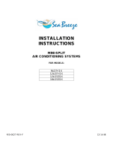
5. Dimensions
5.1 Indoor Unit
121
49
Unit:mm

12
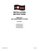
5.2 Outdoor Unit
Unit: mm

13
6. Refrigeration Cycle Diagram
CS/CU-YE9MKX, CS/CU- YE12MKX
CS/CU-YE18MKX
COOLING
HEATING

14
7. Block Diagram
CS/CU-YE18MKX
CS/CU-YE9/12MKX

15
8. Wiring Diagram
CS-YE9MKX,
CS-YE12MKX

16
CU-YE9MKX
CU-YE12MKX

17
CS-YE18MKX

18
CU-YE18MKX

19
9. Printed Circuit Board
9.1 Indoor Unit
9.2 Outdoor Unit
IC104
LED3
LED2
CN-STM3 CN-THSW HA
CN-FB
IC1
X1
IC103
IC2
IC

20
10. Installation Instruction
10.1 Select the Best Location
10.1.1 Indoor Unit
• There should not be any heat source or steam near
the unit.
• There should not be any obstacles blocking the air
circulation.
• A place where air circulation in the room is good.
• A place where drainage can be easily done.
• A place where noise prevention is taken into
consideration.
• Do not install the unit near the door way.
• Ensure the spaces indicated by arrows from the wall,
ceiling, fence or other obstacles.
• Recommended installation height for indoor unit shall
be at least 2.5m.
10.1.2 Outdoor Unit
• If an awning is built over the unit to prevent direct
sunlight or rain, be careful that heat radiation from the
condenser is not obstructed.
• There should not be any animal or plant which could
be affected by hot air discharged.
• Keep the spaces indicated by arrows from wall, ceiling,
fence or other obstacles.
• Do not place any obstacles which may cause a short
circuit of the discharged air.
• If piping length is over the rated length, additional
refrigerant should be added as shown in the table
below:
Example: If the unit is installed at a 10m distance, the
quantity
of additional refrigerant should be 50 g.
…… (10-7.5) m x 20g/m = 50 g
Piping size
Model
Gas Liquid
Rated
Length
(m)
Max
Elevatio
n (m)
Min
Piping
Length
(m)
Max
Piping
Length
(m)
Additional
Refrigeran
t (g/m)
YE9MKX
9.52
(3/8”)
6.35
(1/4")
7.5 5 3 15 20
YE12MKX
9.52
(3/8”)
6.35
(1/4”)
7.5 5 3 15 20
YE18MKX
12.7
(1/2”)
6.35
(1/4”)
7.5 5 3 15 20
11.1.3
Indoor/Outdoor Unit
*This illustration is for explanation purposes only.
The indoor unit will actually face a different way.
/