Page is loading ...

SAFEGUARD
TOTALGUARD
20071 / 20070228 • SAFEGUARD
TM
/ TOTALGUARD
TM
ALL RIGHTS RESERVED
2007
USER’S GUIDE
SAFEGUARD
TOTALGUARD
tm
ENGLISH
20071_20070228_UG_SC9000_EN 08-03-2007 10:07 Pagina 1

Introduction
Safety warnings
BASIC OPTIONS
1. Your Marmitek surveillance system _________________________________________________________________ 5
1.1 Important properties_____________________________________________________________________________________ 6
1.2 Signal range____________________________________________________________________________________________ 7
2. The security console _________________________________________________________________________________ 7
2.1 Installing the console ____________________________________________________________________________________ 8
2.1.1 Connecting the telephone wire______________________________________________________________________ 8
2.1.2 Connecting the AC adapter_________________________________________________________________________ 8
2.1.3 Installing the emergency batteries____________________________________________________________________ 8
2.2 Mounting the security console ____________________________________________________________________________ 9
2.3 The menus _____________________________________________________________________________________________ 9
2.3.1 Choosing your language ___________________________________________________________________________ 10
2.3.2 The menu in English _______________________________________________________________________________ 11
3. Installing remote controls ___________________________________________________________________________ 12
3.1 Key Chain Remote Control KR21 __________________________________________________________________________ 12
3.1.1 Using the Key Chain Remote Control_________________________________________________________________ 12
3.1.2 Registering the Key Chain Remote Control ____________________________________________________________ 12
3.2 Comfort Remote Control SH624 (standard with TotalGuard, optional with SafeGuard) _____________________________ 13
3.2.1 Using the Comfort Remote Control __________________________________________________________________ 13
3.2.2 Registering the Comfort Remote Control______________________________________________________________ 13
4. Installing the sensors ________________________________________________________________________________ 14
4.1 Door/Window Sensor DS90_______________________________________________________________________________ 14
4.1.1 Mounting the Door/Window Sensor DS90_____________________________________________________________ 14
4.1.2 Using the Door/Window Sensor _____________________________________________________________________ 14
4.1.3 Registering a Door/Window Sensor __________________________________________________________________ 15
4.2 Motion Detector MS90 __________________________________________________________________________________ 15
4.2.1 Mounting the Motion Detector MS90 ________________________________________________________________ 15
4.2.2 Using the Motion Detector__________________________________________________________________________ 16
4.2.3 Registering a Motion Detector_______________________________________________________________________ 16
4.3 Smoke Detector SD10 /SD90______________________________________________________________________________ 17
5. Setting up the security console (SC9000) ____________________________________________________________ 17
5.1 Setting the clock ________________________________________________________________________________________ 17
5.2 Storing phone numbers __________________________________________________________________________________ 18
5.3 Recording your own message _____________________________________________________________________________ 18
6. Using the security system ___________________________________________________________________________ 19
6.1 Setting the alarm _______________________________________________________________________________________ 19
6.2 Panic alarm ____________________________________________________________________________________________ 20
6.3 What happens when the alarm goes off? ___________________________________________________________________ 21
6.4 Disarming the system ____________________________________________________________________________________ 21
6.5 Error messages _________________________________________________________________________________________ 21
INDEX
2 MARMITEK
20071_20070228_UG_SC9000_EN 08-03-2007 10:07 Pagina 2

7. Prevention and comfort - ‘Home Automation’_______________________________________________________ 22
7.1 Introduction____________________________________________________________________________________________ 22
7.2 Addressing your modules_________________________________________________________________________________ 23
7.3 Installing the LM12 Lamp/Dimmer Module __________________________________________________________________ 23
7.4 Alarm functions of the Lamp/Dimmer Modules ______________________________________________________________ 23
7.5 Comfort functions of the KR21 Key Chain Remote Control ____________________________________________________ 23
7.6 Comfort functions of the SH624 Comfort Remote Control ____________________________________________________ 24
7.7 Comfort functions of the security console___________________________________________________________________ 24
7.8 Setting the timer ________________________________________________________________________________________ 24
7.9 Clearing the timer settings _______________________________________________________________________________ 25
EXTRA OPTIONS
8. Advanced system functions__________________________________________________________________________ 26
8.1 Setting the delays _______________________________________________________________________________________ 26
8.2 Clearing the memory of your security system ________________________________________________________________ 26
8.3 Changing the access code (PIN) ___________________________________________________________________________ 27
9. Advanced security functions_________________________________________________________________________ 27
9.1 Disarming the siren for silent alarm ________________________________________________________________________ 27
9.2 Arming the chime_______________________________________________________________________________________ 27
9.3 Using wired inputs ______________________________________________________________________________________ 28
9.4 Adding a wired sensor to the Door/Window Sensor DS90 _____________________________________________________ 28
9.5 Emergency sensors ______________________________________________________________________________________ 29
9.6 Deregistering a Door/Window Sensor ______________________________________________________________________ 29
9.7 Deregistering a Motion Detector___________________________________________________________________________ 30
10. Advanced Home Automation functions______________________________________________________________ 30
10.1 Checking the status of the security system __________________________________________________________________ 30
10.2 Installing an extra siren (Marmitek PH7208) _________________________________________________________________ 30
10.3 Using an external universal siren___________________________________________________________________________ 31
10.4 Transceiver function _____________________________________________________________________________________ 31
10.5 All Home Automation functions at a glance _________________________________________________________________ 31
10.6 Basic address for Home Automations functions ______________________________________________________________ 31
11. Telephone functions _________________________________________________________________________________ 33
11.1 Calling the security system _______________________________________________________________________________ 33
11.2 Activating the call-in function _____________________________________________________________________________
33
11.3 Operating the alarm functions via an outside phone __________________________________________________________ 34
11.4 Operate lights and equipment via an outside phone __________________________________________________________ 34
12. Changing the batteries ______________________________________________________________________________ 34
13. Frequently asked questions__________________________________________________________________________ 36
Tabels ________________________________________________________________________________________________ 37
Technical data________________________________________________________________________________________ 38
INDEX
3SAFEGUARD / TOTALGUARD
20071_20070228_UG_SC9000_EN 08-03-2007 10:07 Pagina 3

Introduction
Thank you for purchasing this Marmitek security product. Marmitek security systems are made with care and are of the highest
quality. Please read this user manual carefully and follow up all the instructions.
In this user manual you will find texts marked with a ☺ sign. These texts contain extra information about the functions and can be
skipped.
Safety warnings
• To prevent short circuits, this product should only be used inside and only in dry spaces. Do not expose the components of your
security system to rain or humidity. Do not use the product close to a bath, swimming pool etc.
• Only connect the adapters to the mains after you have checked whether the mains voltage corresponds with the value on the
type tags. Never connect an adapter or cable when it is damaged. In that case, contact your supplier.
• Batteries: keep batteries out of the reach of children. Dispose of batteries as chemical waste. Never use old and new batteries
or different types of batteries together. Remove the batteries when you are not using the system for a longer period of time.
Check the polarity (+/-) of the batteries when inserting them in the product. Wrong positioning can cause an explosion.
• Do not expose the components of your systems to extremely high temperatures or direct sunlight.
• Do not open the product: The device contains live components. The product should only be repaired or serviced by a qualified
repairman.
• In case of improper usage or if you have opened, altered and repaired the product yourself, all guarantees expire. Marmitek
does not accept responsibility in the case of improper usage of the product or when the product is used for purposes other
than specified. Marmitek does not accept responsibility for additional damage other than covered by the legal product
responsibility.
• This product is not a toy. Keep out of reach of children.
INTRODUCTION
4 MARMITEK
20071_20070228_UG_SC9000_EN 08-03-2007 10:07 Pagina 4

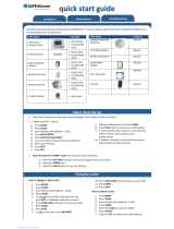
1. Your Marmitek surveillance system
The contents of your set:
The Marmitek SafeGuard system is an effective security system for your home. In this kit you will find the following components:
1. Security console SC9000
2. Motion Detector MS90
3. Door/Window Sensor DS90
4. Key Chain Remote Control KR21
5. AC adapter
6. Accessories: batteries, telephone wire, telephone plug
BASIC OPTIONS
5SAFEGUARD / TOTALGUARD
Marmitek SafeGuard-system
14
32
20071_20070228_UG_SC9000_EN 08-03-2007 10:07 Pagina 5

The Marmitek TotalGuard system is identical to the SafeGuard system, but also contains components for prevention and comfort.
The TotalGuard system also contains the following components:
1. Lamp/Dimmer Module LM12
2. Comfort Remote Control SH624
3. One extra DS90 Door/Window Sensor
☺ All components of the TotalGuard system are available separately and are compatible with the SafeGuard system.
1.1 Important properties
• Receive a telephone message in case of an emergency, wherever you are. The built-in telephone dialler can dial six different
telephone numbers.
• The person called receives a spoken message indicating a burglary or fire alarm is in progress.
• Intelligent sensor control: the console checks functions and battery status.
• Menu control in your own language makes installation and configuration easy.
• Use the phone to listen to what is causing the alarm in your home.
• You can register up to 30 wireless sensors with the console.
BASIC OPTIONS
6 MARMITEK
Marmitek TotalGuard-systeem
3
12
20071_20070228_UG_SC9000_EN 08-03-2007 10:07 Pagina 6

• You can use up to 16 wireless remote controls.
• 2 inputs for wired sensors.
• Silent alarm possible (no siren).
• By calling the system, you can control the system remotely and check the status. The TotalGuard also lets you switch on the
lights.
• Prevention: Your lights are switched on and off in such a way that it appears as if you are home.
1.2 Signal range
The sensors have an open field range of 100 m. Walls, ceilings and other large object will influence the range. The range depends
on your personal living conditions, but is usually between 15 and 30 m.
One other factor that can decrease the range is the presence of other distorting high-frequency signals on the same frequency
(433MHz). RF wireless headphones and wireless speakers can influence the range. They cannot cause a false alarm. Wireless
phones or networks do not influence the system.
2. The security
console
(1) Display.
(2) ARM HOME button
Alarm function for when
you are at home. All
Door/Window Sensors are
activated, but the Motion
Detectors remain unarmed.
(3) ARM AWAY button
Full alarm. All sensors are
activated.
(4) ARMED Indicator
Lights up when the alarm is
switched on.
(5) BATTERY Indicator
Lights up when the back-
up batteries are empty or
not installed.
(6) Telephone connection.
(7) AC adapter connection.
(8) Wired inputs.
(9) Tamper contact.
(10) Emergency battery compartment.
(11) Console buttons.
(12) Menu Start - Call up the menu or step up in the menu.
(13) Menu Start - Call up the menu or step down in the menu.
(14) ON - Switch on a Marmitek X-10 Module (see 7.7).
(15) OFF - Switch off a Marmitek X-10 Module (see 7.7).
(16) OK - Confirm setting.
(17) Clear/bypass - Clear the setting, go up one level in the menu, Bypass function for switching of a sensor.
(18) Built-in microphone.
BASIC OPTIONS
7SAFEGUARD / TOTALGUARD
1 18
14 15 17 12
9 16 1311
6 8
7
10
3254
20071_20070228_UG_SC9000_EN 08-03-2007 10:07 Pagina 7

Display:
1. Zone numbers
Every sensor represents a so-called zone in the system. There are 30 zones for wireless sensors (numbers 1-30 on the display)
and 2 zones for wired sensors (numbers 31 and 32 on the display).
Zone numbers on: Door or window is open.
Zone number flashing slowly: There is a problem with the sensor (6.5).
Zone number flashing quickly: The sensor has been switched off with the Bypass function (6.5).
2. Chime
Chime is switched on when the system is switched off. When this function is activated, you hear a pleasant ding-dong when
someone enters the house (9.2).
3. Space for menu texts and clock
2.1 Installing the console
2.1.1 Connecting the telephone wire
Open the top compartment on your console. Connect the telephone wire to the corresponding connection (6). You can fixate the
wire by looping it behind the hooks on the back of the console.
In case of an analogue phone connection
Insert the other end of the telephone wire into the telephone plug included and connect this to your telephone socket.
☺ In case of an ISDN connection
The console cannot be connected directly to an ISDN connection! If you are using ISDN, you need to connect the alarm system
to an analogue connection of your ISDN console. The telephone wire included, without the plug, fits directly into the analogue
input of your ISDN console. If there are no analogue inputs, please use a converter (check with your telecom supplier). You will
most likely have to dial a 0 on the console to get an outside line. This 0 needs to be programmed in with the telephone
numbers to be able to dial out (see 5.2). You also need to keep in mind that with ISDN in the case of a power failure your
alarm system can no longer dial out. The connection can only be guaranteed with an analogue line.
2.1.2 Connecting the AC adapter
Connect the AC adapter to the corresponding connection (7). Plug the adapter into a 230V wall socket. You can fixate the wire
by looping it behind the hooks on the back of the console. When connecting the adapter and opening the top compartment of
your console, you will see the word ‘TAMPER’ on the display. After closing the compartment, enter your PIN code (factory settings
0000, see 8.3) to remove the word ‘TAMPER’. The display will now read ‘DISARMED’ and you will hear a double tone to confirm.
☺ Please use the AC adapter included in the set
2.1.3 Installing the emergency batteries
Insert 4 AA batteries in the battery compartment (10). Do not forget to check the polarity (+/-).
Preferably use alkaline batteries (not rechargeable batteries). After inserting the batteries and closing the compartment, enter your
PIN code (factory settings 0000, see 8.3) to remove the word ‘TAMPER’. The display will now read ‘DISARMED’ and you will hear
a double tone to conf
BASIC OPTIONS
8 MARMITEK
1 2 3 4 5 6 7 8 9 10 11 12 13 14 15 16
17 18 19 20 21 22 23 24 25 26 27 28 29 30 31 32
1
1
3
2
20071_20070228_UG_SC9000_EN 08-03-2007 10:07 Pagina 8

2.2 Mounting the security console
Choose a good space for the console and make sure you have a wall socket (230V) and a telephone connection close by. For
optimal range it is best to mount the console central to the objects you wish to secure. This ensures that the distance between
the console and the sensors is as short as possible and the range will be sufficient.
Please also ensure that:
1. the console is not placed close to large metal object (radiators, oven, etc.);
2. you have easy access to the console;
3. the console is not too close to other electronic equipment, such as your telephone system, computer or TV.
You can place the console on any flat surface (table, etc.) or mount it onto the wall.
Mounting the console onto the wall
The console can be mounted onto the wall using two screws. On the back of the console you will find two slot holes (heart to
heart distance 96mm). Fitting screws are included in the set.
Setting the console on a flat surface
The rubber caps make sure the console will not move around when using the console.
2.3 The menus
After connecting the console, the display will read ‘HOME CONTROL’. The time will be displayed on the bottom line (for setting
the time, see 5.1).
☺ If you do not see the words HOME CONTROL but TAMPER, you need to close the top compartment on the console. After
closing the compartment, enter your PIN code (factory settings 0000, see 8.3) to remove the word ‘TAMPER’. The display will
now read ‘DISARMED’ and you will hear a double tone to confirm. Then the text HOME CONTROL will be shown.
BASIC OPTIONS
9SAFEGUARD / TOTALGUARD
20071_20070228_UG_SC9000_EN 08-03-2007 10:07 Pagina 9

2.3.1 Choosing your language
All menu items are displayed in English. You can choose any of the other available languages. You can do this as follows:
To access the menu, press the menu or menu button. The display will now read ‘ENTER PIN’.
Enter the 4-digit PIN code (factory setting 0000. See 8.3 for changing the PIN code). For every digit entered, a * will appear on
the display. When the PIN code has been entered correctly, the first menu item will show up on the display.
Use the menu buttons / to go to menu item 7. Options. Press OK to select this menu item. You can also go to this menu item
directly by pressing a 7 on the number pad.
Use the menu buttons / to go to menu item Languages. Press OK to select this submenu item.
Use the menu buttons / to select your language. Press OK to confirm.
Press Clear and then 1 (=Yes) to quit the menu.
BASIC OPTIONS
10 MARMITEK
ENTER PIN
1. INSTALL
7. OPTIONS
LANGUAGES
ENGLISH
QUIT MENU
1.YES 2.NO
20071_20070228_UG_SC9000_EN 08-03-2007 10:07 Pagina 10

☺ Attention: This English language user manual will only use the English menu items.
2.3.2 The menu in English
The menu items in the English language menu are:
1. INSTALL Registering and deregistering sensors and remote controls.
2. SET CLOCK Setting the clock (5.1).
3. PHONE NUMS Setting the phone numbers (5.2).
Submenu:
PHONE 1
PHONE 2
PHONE 3
PHONE 4
PHONE 5
PHONE 6
4. MESSAGE Recording and checking your own spoken message (5.3).
Submenu: 1. RECORD Record your own spoken message
2. REPLAY Listen to your own spoken message
5. NEW PIN Change your PIN code (8.3).
6. MEMORY CLEAR Clear all sensors, remote controls, timers or settings (8.2).
Submenu: CLEAR ALL SENSORS Remove a registered sensor.
CLEAR ALL REMOTES Remove a registered remote control.
CLEAR ALL TIMERS Remove all timer settings at once.
MASTER RESET Clear the memory.
7. OPTIES
Submenu: Submenu:
CHIME - CHIME ON/CHIME OFF Chime on/off when system off (9.2). When the chime is switched on,
the display will show a symbol.
SIREN - SIREN ON/SIREN OFF Switch off siren for silent alarm (9.1).
HOUSECODE Change the HouseCode for Home Automation functions (10.6).
UNITCODE Change the UnitCode for Home Automation functions (10.6).
ANSWER TYPE ANSWER ON/ANSWER OFF/VOICE MAIL (11.2).
SENSOR MODE Use sensors as emergency sensor. See (9.5).
LANGUAGE ENGLISH/FRANÇAIS/DEUTSCH/NEDERLANDS/ITALIANO/ESPANOL/
PORTUGUES/SVENSKA/ROMANA/TÜRKÇE.
8. DELAYS
Submenu:
ENTRY DELAY
The time you get to switch off the system after entering your house (8.1).
EXIT DELAY The time you get before the system is switched on when you leave
your house (8.1).
DIAL DELAY Delay before the system calls out in case of an alarm (8.1).
ANSWER DELAY Delay before the system picks up the phone when dialling in (8.1).
9. SET TIMER
Submenu: NEW TIMER Setting a new timer (7.8).
BASIC OPTIONS
11SAFEGUARD / TOTALGUARD
20071_20070228_UG_SC9000_EN 08-03-2007 10:07 Pagina 11

3. Installing remote controls
3.1 Key Chain Remote Control KR21
1. CONTROLE INDICATOR
Lights up when the remote control transmits radio signals when
pressing the buttons. If the indicator light is not very bright, the
batteries should be replaced.
2. ARM
Switches on the alarm in Arm Away mode (all sensors activated).
3. DISARM
Switches off the security system.
4. LIGHTS ON
Switches on your light modules (7.5).
5. LIGHTS OFF
Switches off your light modules (7.5).
7
+
8. PANIC
If the (red) buttons 7 and 8 are pressed together, the panic alarm is
activated (6.2).
9. BATTERY COMPARTMENT
The battery compartment can be found in the remote control.
3.1.1 Using the Key Chain Remote Control
1. BATTERIES
A new KR21 contains fully charged batteries.
2. ACTIVATING THE KR21.
Keep the ARM button on your remote control pressed for 4 seconds. Release the button. The remote control has now
chosen a unique code, which can be registered with your console.
☺ When pressing the ARM button the LED should flash quickly a few times. When the LED lights up and stays lit, you need to
reactivate the KR21
3.1.2 Registering the Key Chain Remote Control
1. To access the menu, press the menu or menu button. The display will now read ‘ENTER PIN’.
2. Enter your 4-digit PIN code (factory setting 0000. See 8.3 for changing the PIN code). For every digit entered, a * will appear
on the display.
3. When the PIN code has been entered correctly, the word ‘INSTALL’ will show up on the display.
4. Press OK. The display now reads ‘INSTALL ZONE’.
5. Press the ARM button on your key chain remote control. The console will beep to confirm. The display will read ‘RMOT 1 SET’.
☺ If you have more than 1 remote control installed, it will read e.g. RMOT 2 SET, RMOT 3 SET, … RMOT 16 SET. You can register
up to 16 remote controls.
6. Repeat step 5 for every remote control you wish to register.
7. Press CLEAR to go back to the main menu. Press CLEAR again to quit the menu. To confirm your choice, press 1 for Yes or 2
for No. If you choose Yes, you will quit the menu. If you choose No, you go back to the main menu.
☺
You can also remove remote controls from the menu, e.g. when you have lost a remote control. This method is described in 8.2.
☺ Read chapter 12 for information on replacing the batteries..
BASIC OPTIONS
12 MARMITEK
5
8
9
3
1
2
4
7
20071_20070228_UG_SC9000_EN 08-03-2007 10:07 Pagina 12

3.2
Comfort Remote Control SH624 (standard with TotalGuard, optional with SafeGuard, art. no. 09170)
1. PANIC
With this red button the panic alarm can be activated immediately.
2. CONTROL INDICATOR
Lights up when the remote control transmits radio signals when pressing the
buttons.
If the indicator light is not very bright, the batteries should be replaced.
3. CONTROL BUTTONS
For operating the security system and for the comfort functions (see 7.6).
4. DIMMER BUTTON (see 7.6)
5. MODUS SWITCH
Switch to the SEC setting to use the security functions. For settings 1 and 2, see
7.6.
SWITCH IN SEC SETTING:
ARM HOME: The security system is partly armed. All door/widow sensors
are activated, while the motion detectors are switched off.
ARM AWAY: The security system is fully armed. All sensors are activated.
DISARM: Switches off the security system.
6. HOUSECODE SWITCH
Leave the switch set to A for now (see 10.6 for more information).
3.2.1 Using the Comfort Remote Control
1. INSERTING THE BATTERIES
IMPORTANT: When inserting the batteries, the switch should not be in setting 2!
Open the battery compartment on the back of the remote control and insert the
batteries (4x AAA, alkaline). Do not forget to check the polarity (+/-). Close the compartment.
2. ACTIVATING THE SH624
Press the ‘PANIC’ button.
3.2.2 Registering the Comfort Remote Control
1. To access the menu, press the menu or menu button. The display will now read ‘ENTER PIN’.
2. Enter your 4-digit PIN code (factory setting 0000. See 8.3 for changing the PIN code). For every digit entered, a * will appear
on the display.
3. When the PIN code has been entered correctly, the word ‘INSTALL’ will show up on the display.
4. Press OK. The display now reads ‘INSTALL ZONE’.
5. Set the switch to SEC. Press the ARM HOME button on your Comfort Remote Control. The console will beep to confirm. The
display will read ‘RMOT 2 SET’.
a. If you have more than 2 remote controls installed, it will read e.g. RMOT 3 SET, RMOT 4 SET, … RMOT 16 SET. You can
register up to 16 remote controls.
6. Repeat step 5 for every remote control you wish to register.
7. Press CLEAR to go back to the main menu. Press CLEAR again to quit the menu. To confirm your choice, press 1 for Yes or 2
for No. If you choose Yes, you will quit the menu. If you choose No, you go back to the main menu.
☺ Read chapter 12 for information on replacing the batteries.
BASIC OPTIONS
13SAFEGUARD / TOTALGUARD
1
6
2
3
4
5
20071_20070228_UG_SC9000_EN 08-03-2007 10:07 Pagina 13

4. Installing the sensors
4.1 Door/Window Sensor DS90
1. Transmitter part.
2. Magnet contact.
3. Control Indicator – Lights up when a signal is
transmitted.
4. Screw for opening the sensor.
5. Switch for entry delays.
6. Connection for extra wired contact (9.4).
7. Battery compartment.
8. Screw holes for mounting the sensor.
9. Tamper contact.
4.1.1 Mounting the Door/Window Sensor DS90
1. Open the casing by removing screw (4). Mount
the transmitter part on the frame of your door
or window. Do not close the casing yet.
2. Mount the magnet on the moving part of your
door of window. Make sure that the arrows on
the transmitter part (see the lid!) and the magnet are facing each other when the door or window is closed. Keep the distance
between the transmitter part and the magnet (when door or window is closed) as small as possible (max. 4 mm).
☺ If your window or doorframe is slightly countersunk, you can also place
the transmitter part and the magnet at a 90-degree angle.
☺ Once you have decided on a definite place for the sensor, we advise to also
fix the magnet with screws (included).
☺ Aluminium/synthetic frames
Place the sensor as high as possible: This gives the best range. Mark the place
for the transmitter and the magnet. Do not place the magnet directly on a
metal surface. In case of metal frames, or synthetic frames with a metal core,
place a piece of wood or plastic (min. 5mm thick) between the magnet and
the frame. On metal frames the space between the sensor and the magnet
should be no more than 3mm when the window or door is closed.
☺ Sliding windows
In case of sliding windows the sensor and magnet should NOT be allowed to slide along each other horizontally. Place the
sensor and magnet in such a way that when closing the window the magnet and sensor approach each other vertically.
4.1.2 Using the Door/Window Sensor
1. If you have not yet opened the transmitter, please do so now by unscrewing screw (4).
2. Insert the batteries (2xAAA, alkaline) into the battery compartment. Do not forget to check the polarity.
3. Set the switch for entry delay (5) to MIN when you have installed the sensor on a window and on MAX when the sensor is
installed on a door. When the switch is set to MAX, you have time to open and close the door (standard setting 30 sec). This
delay to enter your house and switch off the system without triggering the alarm can be altered (see 8.1). If you want an
instant alarm (on e.g. the backdoor), set the switch to MIN.
4. Keep the tamper contact (9) on the transmitter pressed for 4 seconds. Release the button. The door/window sensor has now
chosen a unique code, which can be registered with your console.
BASIC OPTIONS
14 MARMITEK
12
3
4
5
7
8
8
6
9
20071_20070228_UG_SC9000_EN 08-03-2007 10:07 Pagina 14

4.1.3 Registering a Door/Window Sensor
1. To access the menu, press the menu or menu button. The display will now read ‘ENTER PIN’.
2. Enter your 4-digit PIN code (factory setting 0000. See 8.3 for changing the PIN code). For every digit entered, a * will appear
on the display.
3. When the PIN code has been entered correctly, the word ‘INSTALL’ will show up on the display.
4. Press OK.
5. Open your door or window. The console will beep to confirm. The display will read ‘ZONE 1 SET’.
☺ A memory space for a sensor is called a zone. If you have more than 1 sensor installed, it will read e.g. ZONE 2 SET, ZONE 3
SET, … ZONE 30 SET.
☺ You can choose in which zone you want to install the sensor. If you want to install the sensor in zone 3, press 3 on the number
pad before executing step 5.
☺ You will find a table in which you can write down which zone contains which sensor at the back of this user manual. We
advise you to write down which sensor you have registered in which zone
6. Repeat step 5 for every door/window sensor you wish to register.
7. Press CLEAR to go back to the main menu. Press CLEAR again to quit the menu. To confirm your choice, press 1 for Yes or 2
for No. If you choose Yes, you will quit the menu. If you choose No, you go back to the main menu.
☺ Read chapter 12 for information on replacing the batteries.
4.2 Motion Detector MS90
1. Battery compartment.
2. Control Indicator – Lights up when a signal is
transmitted.
3. TEST button.
4. Sensitivity switch 1/2 – In setting 1 the sensor
will instantly react to movement, in setting 2
the sensor is less sensitive and will only react
after registering two movements.
5. Tamper contact.
4.2.1 Mounting the Motion Detector MS90
The motion detector works by detecting changes
in temperature. Do not mount the detector too
close to a heater or air conditioner.
The motion detector has a range of 6-10 m and an angle of 90°. Because of the special lens the sensor ‘looks down’. Always
mount the MS90 at a height of about 180 cm from the floor and place it in such a way that the detector can cover the area you
want to secure. The mounting bracket can be placed at an angle (90°) or directly against the wall.
BASIC OPTIONS
15SAFEGUARD / TOTALGUARD
1
3
4
5
2
20071_20070228_UG_SC9000_EN 08-03-2007 10:07 Pagina 15

4.2.2 Using the Motion Detector
1. Open the battery compartment and insert the batteries (2x AA, alkaline).
2. Keep the TEST button (3) pressed for about 4 seconds. The LED will flash once. Release the button. The LED will flash twice.
The motion detector has now chosen a unique code, which can be registered with your console.
3. Place the motion detector upside down so that it cannot detect any movement during registration.
Test mode: Testing the location of your motion detector
1. Set the switch to 1.
2. Press the TEST button (3) until the indicator (2) flashes twice.
3. Wait 20 seconds.
4. Walk in front of the sensor. The indicator (2) lets you know when a movement has been detected. This allows you to check
whether the sensor has been mounted on the right place.
5. Press the TEST button again to be able to use the sensor as normal.
☺ After 2 minutes the motion detector will go back to the normal mode.
4.2.3 Registering a Motion Detector
1. To access the menu, press the menu or menu button. The display will now read ‘ENTER PIN’.
2. Enter your 4-digit PIN code (factory setting 0000. See 8.3 for changing the PIN code). For every digit entered, a * will appear
on the display.
3. When the PIN code has been entered correctly, the word ‘INSTALL’ will show up on the display.
4. Press OK. The display will read ‘INSTALL ZONE’.
5. Press the TEST button of the motion detector or turn it around, so that the sensor will detect movement. The console will beep
to confirm. The display will read ‘ZONE …’. SET’.
☺ A memory space for a sensor is called a zone. If you have more than 1 sensor installed, it will read e.g. ZONE 2 SET, ZONE 3
SET, … ZONE 30 SET.
☺ You can choose in which zone you want to install the sensor. If you want to install the sensor in zone 3, press 3 on the number
pad before executing step 5.
☺ You will find a table at the back of this user manual in which you can write down which zone contains which sensor. We
advise you to write down which sensor you have registered in which zone.
6. Repeat step 5 for every motion detector you wish to register.
7. Press CLEAR again to quit the menu. To confirm your choice, press 1 for Yes or 2 for No. If you choose Yes, you will quit the
menu. If you choose No, you go back to the main menu.
☺ Read chapter 12 for information on replacing the batteries.
BASIC OPTIONS
16 MARMITEK
20071_20070228_UG_SC9000_EN 08-03-2007 10:07 Pagina 16

4.3 Smoke Detector SD10 / SD90
The Marmitek Smoke Detector will make sure you are warned in case of a fire. When
you’re at home, the built-in siren will be triggered. Combined with your security system the
internal siren, the telephone dialler and the lights will be activated. This gives you an
optimal warning and makes sure your exits are well lit. If you are away from home, you will
receive a warning via your mobile phone.
☺ The telephone message indicates that the emergency sensor is triggered and that it is
not the burglar alarm. This is done by adding an extra message to your own spoken
telephone message. This standard message (4 languages: English, German, French,
Dutch) is pre-programmed into your system.
Consult the user manual for your smoke alarm for instructions on using
the smoke alarm with your security system.
5. Setting up the security console (SC9000)
5.1 Setting the clock
1. To access the menu, press the menu or menu button. The display will now read ‘ENTER PIN’.
2. Enter your 4-digit PIN code (factory setting 0000. See 8.3 for changing the PIN code). For every digit entered, a * will appear
on the display.
3. When the PIN code has been entered correctly, the word ‘INSTALL’ will show up on the display.
4. Use the menu buttons / to go to menu item 2. SET CLOCK. Press OK to select this menu item. You can also go to this
menu item directly by pressing a 2 on the number pad.
5. Use the number pad to enter the new time (24 hour notation), followed by OK. The display now reads ‘INSTALL’.
6. Press CLEAR again to quit the menu. To confirm your choice, press 1 for Yes or 2 for No. If you choose Yes, you will quit the
menu. If you choose No, you go back to the main menu.
☺ If you press CLEAR while entering the time, the time entered will be deleted.
BASIC OPTIONS
17SAFEGUARD / TOTALGUARD
20071_20070228_UG_SC9000_EN 08-03-2007 10:07 Pagina 17

5.2 Storing phone numbers
The Marmitek SC9000 console is equipped with a telephone dialler. In the case of an alarm up to 6 telephone numbers can be
dialled. All persons called will be able to listen to the message you have recorded (5.3). The message needs to be confirmed by
the person answering the phone by pressing a 0 on their phone. The telephone dialler then knows the next number does not
need to be called.
You are not allowed to use emergency numbers, i.e. the police, unless you have been granted special permission.
First make a list with the phone numbers you want to enter, in the order they need to be dialled. If you have connected the
console via an ISDN phone system, you may need to add a 0 in front of the telephone number to get an external line.
1. To access the menu, press the menu or menu button. The display will now read ‘ENTER PIN’.
2. Enter your 4-digit PIN code (factory setting 0000. See 8.3 for changing the PIN code). For every digit entered, a * will appear
on the display.
3. When the PIN code has been entered correctly, the word ‘INSTALL’ will show up on the display.
4. Use the menu buttons / to go to menu item 3. PHONE NUMS. Press OK to select this menu item. You can also go to this
menu item directly by pressing a 3 on the number pad.
5. Use the menu buttons / to go to the memory space where you want to enter a telephone number (PHONE 1, PHONE 2 …
PHONE 6).
6. Press OK when you have arrived at the memory space. After pressing OK at PHONE 1, the display will read SET PH 1.
7. Enter the telephone number. Press the OFF button for a dial pause (use a dial pause between the extra 0 and the telephone
number when the console is connected to an ISDN phone system. A small letter ‘P’ can now be seen on the display).
8. Press OK. You will now automatically go to the next memory space.
9. Press CLEAR again to quit the menu. To confirm your choice, press 1 for Yes or 2 for No. If you choose Yes, you will quit the
menu. If you choose No, you go back to the main menu.
☺ If you press CLEAR while entering a telephone number, the number entered will be deleted.
☺ If you program less than 6 numbers, the console will try to contact you at these numbers several times in case of an alarm.
As soon as the call is confirmed, the console will stop dialling out.
5.3 Recording your own message
You can record your own message that will be used by the telephone dialler. The message can be up to 12 seconds long. Make
sure the message is not too short, because this will cause a long silence when the message is played.
☺ Example: This is the security system of ...... Press 0 after this message to hear what is going on in my house.
Please take the steps that we agreed.
1. To access the menu, press the menu or menu button. The display will now read ‘ENTER PIN’.
2. Enter your 4-digit PIN code (factory setting 0000. See 8.3 for changing the PIN code). For every digit entered, a * will appear
on the display.
3. When the PIN code has been entered correctly, the word ‘INSTALL’ will show up on the display.
4. Use the menu buttons / to go to menu item 4. MESSAGE. Press OK to select this menu item. You can also go to this menu
item directly by pressing a 4 on the number pad.
5. Press 1 for RECORD.
6. The display will now read ‘PLEASE WAIT’.
7. When the display reads ‘SPEAK NOW’ you can record your message (max. 12 seconds). The distance to the microphone should
be no more than 30 cm.
8. After recording, wait until the RECORD/REPLAY menu comes up again.
BASIC OPTIONS
18 MARMITEK
20071_20070228_UG_SC9000_EN 08-03-2007 10:07 Pagina 18

9. Press 2 (REPLAY) to listen to the message you have just recorded.
10.
Press CLEAR again to quit the menu. To confirm your choice, press 1 for Yes or 2 for No. If you choose Yes, you will quit the
menu. If you choose No, you go back to the main menu.
6. Using the security system
6.1 Setting the alarm
The system has two different alarm functions:
ARM AWAY: Full alarm. All sensors are activated.
ARM HOME: Partial alarm. All door/window sensors are activated, but the motion detectors are not armed. This
means you can walk around in your home, while the ‘shell’ of the house is protected.
Switching on the ARM AWAY function
Via the console
Press the ARM AWAY button on the console. The system will be activated after a short delay
(delay can be set, see exit delay 8.1). During the delay you will hear a couple of tones at the same pitch.
☺ After switching the system to ARMED AWAY mode, the entry delay will be used for DS90 Door/Window Sensors (DS90 switch
set to MAX) when you enter the house. This means you have enough time to switch off the system via the console without
triggering the alarm. The delay times can be changed, see 8.1.
Via the Key Chain Remote Control KR21
Press the ARM button. The alarm is switched on instantly.
Please note: Make sure the front door is closed when you switch on the device.
Via the Comfort Remote Control SH624
Set the switch to SEC. Press the ARM AWAY button. The alarm is switched on instantly.
BASIC OPTIONS
19SAFEGUARD / TOTALGUARD
ARMED AWAY
20071_20070228_UG_SC9000_EN 08-03-2007 10:07 Pagina 19

Switching on the ARM HOME function
Via the console
Press the ARM HOME button on the console. The alarm is switched on instantly.
Via the Key Chain Remote Control KR21
You cannot switch on the ARM HOME function with your remote control.
Via the Comfort Remote Control SH624
Set the switch to SEC. Press the ARM HOME button. The alarm is switched on instantly.
6.2 Panic alarm
The panic alarm can be switched on in case of an emergency, independent of whether the security system is switched on or off.
☺ The telephone message indicates the emergency sensor is triggered and that it is not the burglar alarm. This is done by adding
an extra message to your own spoken telephone message. This standard message (4 languages: English, German, French,
Dutch) is pre-programmed into your system.
You can activate the panic alarm in two ways:
1. Activate the alarm via the KR21 Key Chain Remote Control
Keep the bottom two buttons of the remote control pressed. The panic alarm is instantly triggered.
Depending on the console settings the siren will be triggered or not (see 9.1).
BASIC OPTIONS
20 MARMITEK
ARMED HOME
20071_20070228_UG_SC9000_EN 08-03-2007 10:07 Pagina 20
/