
.
User manual for mymbCONNECT24 server
Item no. 0690; 0691 / Version: 2.1.x

Page 2 of 20 | Item no. 0690; 0691 / Version: 2.1.x | 26.07.2016
Copyright © MB Connect Line GmbH 2015
No part of this document and its contents may be reproduced, used or distributed without our express permis-
sion. Damages will be claimed in the event of infringement. All rights reserved.
This documentation describes the application of the mymbCONNECT24.midi /.maxi/.mini servers - item no
0690 and 0691 from firmware version V 2.1.
Despite a detailed description of the device and its functions, we cannot be held liable for the correctness of the
content. The latest information can be obtained on our homepage. We welcome any comments or suggestions
for improvement.
Trademarks
The use of any trademark not listed herein is not an indication that it is freely available for use.
MB Connect Line confirms that the mymbCONNECT24 device complies with the basic requirements and
all other relevant provisions of European Directive 1999/5/EC. To see the Declaration of Conformity, visit:
www.mbconnectline.com
Issued by:
MB Connect Line GmbH
Remote Maintenance Solutions
Dinkelsbühler Str. 6
91550 Dinkelsbühl
Germany
Tel.:
+49 (0) 700 622 666 32 /
+49 (0) 700MBCONNECT
Website:
www.mbconnectline.com
Release notes
Date Version Previous version Comment
2016 / 07 / 28 V 2.1.x V 2.x Description of the new server hardware

Table of contents | Page 3 of 20
Table of contents
1 General................................................................................................................................................... 4
1.1 Brief description............................................................................................................................4
1.2 Features........................................................................................................................................4
1.3 Safety instructions.........................................................................................................................4
2 Technical data.......................................................................................................................................5
3 Included in delivery.............................................................................................................................. 6
4 Technical Support.................................................................................................................................6
5 Displays, controls and connections...................................................................................................7
6 Interface assignments.......................................................................................................................... 9
7 First time operation............................................................................................................................ 10
7.1 Console.......................................................................................................................................10
7.2 Web interface (administration interface).....................................................................................11
8 Account Management.........................................................................................................................15
9 Factory settings on delivery..............................................................................................................20

Page 4 of 20 | Item no. 0690; 0691 / Version: 2.1.x | 26.07.2016
1 General
1.1 Brief description
The VPN connection portal mymbCONNECT24 offers you optimum flexibility and security.
mymbCONNECT24 combines the advantages of a portal solution with the special requirements of your com-
pany. Administration and hardware stay in house. This combination of a VPN portal with hardware, which acts
as an intelligent communication point including integrated user and device administration, is intended both for
service personnel user accounts and mbNET / mbSPIDER accounts for machines and systems.
1.2 Features
Features
•
Tunnel end points do not end outside of your company
•
Administration and hardware stay in house
•
Secure system, comprising a VPN server and reliable VPN terminal devices
•
Simple, clearly structured client and server configuration
•
Highly available backup system
1.3 Safety instructions
Safety instructions
•
The device is built to the latest technological standards and recognized safety standards (see Declara-
tion of Conformity).
•
The device must be installed in a dry location. No liquid must be allowed to get inside the device, as
this could result in electric shocks or short circuits.
•
The device is for indoor use only.
•
Never open the device chassis. Unauthorized opening and improper repair can pose a danger to the
user. Unauthorized modifications are not covered by the manufacturer's warranty. Opening up the de-
vice voids the warranty.
•
The device must be disposed of in line with European regulations and German legislation on electron-
ics and electronic devices, and not in general household waste. The device should be disposed of ac-
cordingly.

Technical data | Page 5 of 20
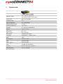
2 Technical data
mymbCONNECT24.mini
Voltage V (ADC)
100 - 240 VAC 50 / 60 Hz
(ext. power pack DC 12 V / 60 W)
Power input Max. 5 A at 12 VDC
Protection class IP 20
Area of application Dry environments
Operating temperature 0 - 40°C
Storage temperature -20 - +70°C
Humidity 10 - 90% (non-condensing)
Weight Approx. 2.5 kg
Dimensions
(max. in mm)
W x H x D:
232 x 44 x 152
Form factor Compact size chassis
Processor Intel® Atom™ C2358 1.7 GHz
RAM 2 GB
WAN interface Ethernet 1 GBit
VPN Ethernet 1 GBit
LAN 1 - LAN 2 Ethernet 1 GBit
USB 1 x USB 2.0; 1x USB 3.0
Console RS232 via RJ type connector
General license CE; FCC class B
Table 1: Technical data

Page 6 of 20 | Item no. 0690; 0691 / Version: 2.1.x | 26.07.2016
3 Included in delivery
mymbCONNECT24.mini
•
mymbCONNECT24.mini, compact size chassis
•
Serial cable (RJ45 for RS232 console access)
•
Power pack adapter for power supply (input 100 - 240 VAC; output 12 VDC, 60 W)
•
Schuko low-power device connecting cable
If any of these parts are missing or damaged, please contact:
MB CONNECT LINE GMBH
Remote Maintenance Solutions
Winnettener Str. 6
91550 Dinkelsbühl
Germany
Tel.:
+49 (0) 700 622 666 32 /
+49 (0) 700 MBCONNECT
E-mail: [email protected]
Website: www.mbconnectline.de
Keep the box and the original packaging in case you have to send the device in for repair at a later date.
4 Technical Support
For technical support (FAQ, troubleshooting, most recent information, etc.) see our website
www.mbconnectline.com.
For support enquiries, always give the serial number of your router.
E-mail: [email protected]
Tel.: (EU) +49 (0) 98 51 / 58 25 29 900 / (US) +1-630-797-6067

Displays, controls and connections | Page 7 of 20
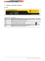
5 Displays, controls and connections
Front view
LED designation Description
Power Lights up when the power is on
Ready Lights up when the device is ready for operation
HDD Lights up when the hard drive is accessed
LAN 1 1. network interface for the local network
LAN 2 2. network interface for the local network
VPN Network interface for direct access to the VPN network
WAN Network interface for access to the Internet

Page 8 of 20 | Item no. 0690; 0691 / Version: 2.1.x | 26.07.2016
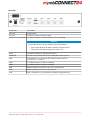
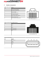
Rear view
Designation Description
ON | OFF Toggle switch
DC+12V Connection socket for power supply
Restore Factory Settings Countersunk button - resets the device to factory settings
ADVICE
To reset the device to factory settings, proceed as follows:
•
Press and hold down the button until the Rdy LED flashes
•
Then release the button and press it again, once
Reset Countersunk button for rebooting the device
CONSOLE Console access interface for basic configuration of the system
USB USB interfaces (e.g. to backup file external storage devices)
1 = USB 2.0; 2 = USB 3.0
LAN 1 1. network interface for the local network
LAN 2 2. network interface for the local network
VPN Network interface for direct access to the VPN network
WAN Network interface for access to the Internet
USB USB 2.0 interfaces (e.g. to backup file external storage devices)

Interface assignments | Page 9 of 20
6 Interface assignments
Pinout of the RJ45 interface
Pin Signal
1 Data Set Ready (DSR)
2 Request to Send (RTS)
3 Ground (GND)
4 Transmit Data (TXD)
5 Receive Data (RXD)
6 Data Carrier Detect (DCD)
7 Clear to Send (CTS)
8 Data Terminal Ready (DTR)
Pinout of LAN, VPN and WAN interfaces
Pin Signal
1 TX+
2 TX-
3 RX+
4 Not connected
5 Not connected
6 RX-
Pinout of USB interface
Pin Signal
1 VCC (+5 V)
2 -Data
3 +Data
4 GND

Page 10 of 20 | Item no. 0690; 0691 / Version: 2.1.x | 26.07.2016
7 First time operation
The LAN IP address of the device can be preconfigured or accessed on the shell via the console interface. For
other settings, the device must be accessed using the browser via the LANx interface.
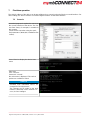
7.1 Console
A terminal program is required to connect to
the console interface of the device. The Tel-
net client "Putty", for example, is suitable for
this purpose.
Create a new connection using the speci-
fied parameters (38400,8,N,1 hardware flow
control).
Press "Enter" to display the device Start
menu.
After login
User: "console"
Password: "console"
the main menu is displayed. The various
options are available to select.
ADVICE
Standard login information MUST be
changed for security reasons.
The changes can be made on the web
interface (backend) under >Remote Ac-
cess / Access Settings<.

First time operation | Page 11 of 20
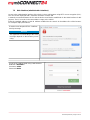
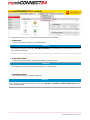
7.2 Web interface (administration interface)
Access to the administration interface of the device is via a web browser using HTTP secure encryption (SSL).
The view is best displayed with a minimum resolution of 1024x 768.
A network connection between the PC and the device must first be established via the LANx interface for this
purpose. The PC must be in the same address range as the LAN IP.
Enter the standard address or LAN IP address modified via the console in the address line of the browser.
For example: https://192.168.0.1.
Trust the server despite HTTPS Certificate
security message.
ADVICE
The appearance and handling of the safety
message depends on the browser you are
using.
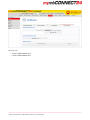
Log in on the LAN backend using a web browser.
Default IP: 192.168.0.1
Username: admin
Password: admin

Page 12 of 20 | Item no. 0690; 0691 / Version: 2.1.x | 26.07.2016
ADVICE
Change unconditionally and without delay the default login information!
The changes can be made in the System > User management menu.
ADVICE
Block this user will lead to exclusion from the server backend. Registration on the system is no longer
possible.

First time operation | Page 13 of 20
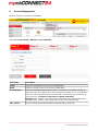
To configure the server you can use the following Setup Wizards available:
1 WAN Wizard
Use this Assistant to configure your WAN Settings
ADVICE
The entered IP address in the field "Fix public IP-address" is the address to connect the devices, which
were created in the portal.
2 Registration Wizard
Use this Assistant to register your mymbCONNECT24.virtual server.
ADVICE
The registration code can be found in the delivery note of your order.
3 Certifikation Wizard
This wizard will help you add the certificates.
ADVICE
After completing the Certificate Wizard, check under System > Certificate > Diffie-Hellman key whether
a DH key was created.

Page 14 of 20 | Item no. 0690; 0691 / Version: 2.1.x | 26.07.2016
Here you can
•
import a Diffie-Hellman Key
•
create a Diffie-Hellman Key

Account Management | Page 15 of 20
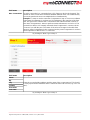
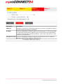
8 Account Management
Here you create an account for the frontend.
Start under Control Panel > Wizard the Account Wizard
Field name Description
E-Mail Enter the email address of the account administrator.
Name Enter the company name of the account administrator.
Account name Choose a meaningful unique name for this account. This name will be used for de-
vices and users on the front end. In order to login to the portal you use a combination
of the user name (specified on the front end) and account name (e.g."username" @
"account name"). Use the account name no special characters!
Example: Enter "mueller" as account name. The front end user will later login with
admin@mueller. "admin" is the default name for the user of the front end.
Max. devices Enter the maximum numberof devices allowed for the account user.

Page 16 of 20 | Item no. 0690; 0691 / Version: 2.1.x | 26.07.2016
Field name Description
Max. Connections An active connection is a connection from a PC client to a device via the portal. The
number of active connections will decide whether different users can simultaneously
access the portal and connect to multiple devices simultaneously.
Example: To setup an active connection. Programmer 1 logs on via access software
to the portal. Programmer 1 can then see his equipment in the overview of the front
end. The green icon confirms that a connection to the Internet and the Portal is ac-
tive. Next, if Programmer 1 wants to perform remote maintenance on Device 1. The
connection to Device 1 is instantly activated, when Programmer 1 connects via the
"Connect" icon with the peer. The status of the unit now changes in the table from
green to yellow. Programmer 2 then connects into the portal. Programmer 2 can then
see Programmer 1 with Device 1 is connected.
By clicking on "Next >" go to Step 2.
Field name Description
Street
Zip
City
Country
First name
Last name
Enter the account holders address and the name of the contact person. This should
in every aspect be the individual whom controls the front end account (e.g. User "ad-
min").
By clicking on "Next >" go to Step 3.

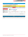
Account Management | Page 17 of 20
Field name Description
VPN Port Determine on which TCP port the OpenVPN server to respond. The default of 1194 is
the official IANA port number for OpenVPN.
IP Range Select your appropriate IP address range for the VPN network. You have the possibil-
ity of the various private-use IP address ranges to choose which were determined in
accordance with RFC1918. The default setting is "10.0.0.0 to 10.255.255.255" and is
suitable for most applications.
User/Device Count Select your appropriate IP address range for the VPN network (251 IP addresses,
Netmask / 24 to 32763 IP addresses, Netmask / 17).
By clicking on "Next >" go to Step 4.

Page 18 of 20 | Item no. 0690; 0691 / Version: 2.1.x | 26.07.2016
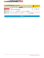
In step 4, you will get an overview of the account information. By clicking on the "Done" button, your settings
are saved and you are automatically forwarded to the Control Panel.

Account Management | Page 19 of 20
ADVICE
The number of accounts depends on the respective license.

Page 20 of 20 | Item no. 0690; 0691 / Version: 2.1.x | 26.07.2016
9 Factory settings on delivery
Usernames and passwords
The device is shipped with the following usernames and password preset:
Web interface:
Username: admin
Password: admin
ADVICE
Standard login information MUST be changed for security reasons. The changes can be made on the web
interface (backend) under >User Administration<.
Console:
Username: console
Password: console
ADVICE
Standard login information MUST be changed for security reasons. The changes can be made on the web
interface (backend) under >Remote Access / Access Settings<.
IP addresses:
The device is set to the following IP addresses in the factory:
LAN IP address: 192.168.0.1
WAN IP: DHCP
-
 1
1
-
 2
2
-
 3
3
-
 4
4
-
 5
5
-
 6
6
-
 7
7
-
 8
8
-
 9
9
-
 10
10
-
 11
11
-
 12
12
-
 13
13
-
 14
14
-
 15
15
-
 16
16
-
 17
17
-
 18
18
-
 19
19
-
 20
20


MB Connect Line mymbCONNECT24.mini User manual
- Type
- User manual
- This manual is also suitable for
Ask a question and I''ll find the answer in the document
Finding information in a document is now easier with AI
Other documents
-
Watts Duplex Strainer Ordering Guide
-
LevelOne AMG-2000 User manual
-
-
Billion BiPAC 4700ZU User manual
-
Draytek Vigor2762 Owner's manual
-
Billion BiPAC 7404VNOX User manual
-
Alcatel-Lucent AOS-W 6.5.3.x User manual
-
Draytek Vigor2765 Owner's manual
-
Mueller Company 040A236140RN Installation guide
-
 Peplink Balance_One Owner's manual
