Garmin 400C User manual

Category
Navigators
Type
User manual

This manual is also suitable for

Fishfinder 400C
owner’s manual
© 2006, 2007 Garmin Ltd. or its subsidiaries
Garmin International, Inc.
1200 East 151
st
Street,
Olathe, Kansas 66062, USA
Tel. (913) 397.8200 or (800) 800.1020
Fax (913) 397.8282
Garmin (Europe) Ltd.
Liberty House
Hounsdown Business Park,
Southampton, Hampshire, SO40 9RB UK
Tel. +44 (0) 870.8501241 (outside the UK)
0808 2380000 (within the UK)
Fax +44 (0) 870.8501251
Garmin Corporation
No. 68, Jangshu 2
nd
Road,
Shijr, Taipei County, Taiwan
Tel. 886/2.2642.9199
Fax 886/2.2642.9099
All rights reserved. Except as expressly provided herein, no part of this manual may be reproduced, copied, transmitted, disseminated, downloaded or stored in
any storage medium, for any purpose without the express prior written consent of Garmin. Garmin hereby grants permission to download a single copy of this
manual onto a hard drive or other electronic storage medium to be viewed and to print one copy of this manual or of any revision hereto, provided
that such electronic or printed copy of this manual must contain the complete text of this copyright notice and provided further that any unauthorized
commercial distribution of this manual or any revision hereto is strictly prohibited.
March 2007 Part Number 190-00757-00 Rev. C Printed in Taiwan
Information in this document is subject to change without notice. Garmin reserves the right to change or improve its products and to make changes in the content
without obligation to notify any person or organization of such changes or improvements. Visit the Garmin Web site (www.garmin.com) for current updates and
supplemental information concerning the use and operation of this and other Garmin products.
Garmin
®
, CANet
TM
, See-Thru
®
, and Ultrascroll
TM
are registered trademarks or trademarks of Garmin Ltd. or its subsidiaries and may not be used without the
express permission of Garmin.
Fishnder 400C Owner’s Manual i
IntroductIon
IntroductIon
The Fishnder 400C is a full-featured, color sonar that offers a choice
of display styles, a dual beam or dual frequency option, and more.
Fishnder 400C Tips and Shortcuts
Press HOME from any screen to return to the Home screen.
Press
MENU from any of the main screens to access
advanced settings.
Press and release the
POWER key to adjust the display
settings.
Quick Links
Installing the Fishnder 400C: page 1
Mounting the Fishnder 400C: page 2
Installing the Transducer: page 4
Basic Operation: page 15
Customizing the Fishnder 400C: page 21
Changing the System Settings: page 23
Customizing the Transducer Settings: page 23
Advanced Settings: page 25
Alarms and Messages: page 28
ii Fishnder 400C Owner’s Manual
IntroductIon
Table of Contents
Introduction ...........................................................................i
Fishnder 400C Tips and Shortcuts ....................................... i
Quick Links ............................................................................... i
Product Registration .............................................................. iii
Caring for the Fishnder 400C .............................................. iii
Warnings ................................................................................. iv
Important Information ............................................................ iv
Installing the Fishnder 400C ............................................1
Step 1: Select a Location for the Fishnder ......................... 1
Step 2: Mount the Fishnder .................................................. 2
Step 3: Install the Transducer ................................................ 4
Step 4: Install the Wiring Harness ....................................... 10
Step 5: Test the Installation .................................................. 13
Basic Operation .................................................................15
Turning the Fishnder 400C On or Off ................................ 15
Adjusting the Backlight Setting ........................................... 15
Using Simulator Mode .......................................................... 15
Using the Fishnder 400C Keypad ...................................... 15
Understanding the Home Screen ......................................... 16
Understanding the Full Screen ............................................ 17
Understanding the Split Zoom Screen ................................ 17
Understanding the Flasher Screen ...................................... 18
Understanding the Split Freq Screen .................................. 18
Understanding the Numbers Screen ................................... 19
Understanding the Temp Log Screen .................................. 19
Understanding the Congure Screen .................................. 20
Customizing the Fishnder 400C .....................................21
Setting Alarms ....................................................................... 21
Changing the Display Settings ............................................ 21
Changing the Sonar Settings ............................................... 22
Changing the System Settings ............................................ 23
Conguring Transducer Settings ........................................ 23
Customizing Units of Measure ............................................. 24
Advanced Settings ............................................................25
Resetting the Odometer ........................................................ 26
Setting the Temp Log Duration and Scale .......................... 26
Appendix ............................................................................27
Specications ........................................................................ 27
Optional Accessories ............................................................ 27
Alarms and Messages ........................................................... 28
Limited Warranty ................................................................... 29
Declaration of Conformity (DoC) ......................................... 30
Software License Agreement ............................................... 30
Index ...................................................................................31
Fishnder 400C Owner’s Manual iii
IntroductIon
Product Registration
Help us better support you by completing our online registration
today! Connect to our Web site at www.garmin.com/registration/.
Use this area to record the serial number (8-digit number located on
the back of the Fishnder 400C) in case your Fishnder 400C needs
service. Keep the original sales receipt, or a photocopy, in a safe
place.
Serial Number: ___ ___ ___ ___ ___ ___ ___ __
Contact Garmin
Contact Garmin if you have any questions while using your
Fishnder 400C. In the USA contact Garmin Product Support
by phone: (913) 397-8200 or (800) 800-1020, Monday–Friday,
8 AM–5 PM Central Time; or go to www.garmin.com/support/, and
click Product Support.
In Europe, contact Garmin (Europe) Ltd. at +44 (0) 870.8501241
(outside the UK) or 0808 2380000 (within the UK).
Tell Us What You Think
Tell us how you like this manual! Fill out the Product
Documentation Survey. Go to www.garmin.com/contactUs/, and
click Product Documentation Survey.
Caring for the Fishnder 400C
The case is constructed of high-quality materials and does not
require user maintenance, except cleaning.
Cleaning the Case
Clean the unit’s outer casing (except for the screen) using a cloth
dampened with a mild detergent solution and then wipe dry. Avoid
chemical cleaners and solvents that may damage plastic components.
Cleaning the Screen
The unit’s lens is coated with a special anti-reective coating that
is sensitive to skin oils, waxes and abrasive cleaners. Cleaners
containing ammonia, alcohol, abrasives, or anti-grease detergents
will harm the anti-reective coating. It is important to clean the lens
using an eyeglass lens cleaner (that is specied as safe for anti-
reective coatings) and a clean, lint-free cloth.
Water Immersion
The unit is waterproof to IEC Standard 60529 IPX7. It can
withstand immersion in 1 meter of water for 30 minutes. Prolonged
submersion can cause damage to the unit. After submersion, be
certain to wipe and air dry the unit before reuse.
iv Fishnder 400C Owner’s Manual
IntroductIon
Failure to avoid the following potentially hazardous situations could result in an accident or collision resulting in death or serious injury.
When navigating, carefully compare information displayed on the unit to all available navigation sources, including information from visual
sightings, and maps. For safety, always resolve any discrepancies or questions before continuing navigation.
WARNING: This product, its packaging, and its components contain chemicals known to the State of California to cause cancer, birth defects, or reproductive
harm. This Notice is provided in accordance with California’s Proposition 65. See www.garmin.com/prop65 for more information.
Warnings
Important Information
The California Waste Recycling Act of 2003 requires the recycling of certain electronics. For more information on the applicability to this product, see
www.erecycle.org.
Hg
- LAMPS INSIDE THIS PRODUCT CONTAIN MERCURY AND MUST BE RECYCLED OR DISPOSED OF ACCORDING TO LOCAL,
STATE, OR FEDERAL LAWS.
For more information go to:
www.garmin.com/aboutGarmin/environment/disposal.jsp.
Fishnder 400C Owner’s Manual
InstallIng the FIshFInder 400c
To successfully operate your Fishnder 400C, you must properly
install the shnder and all of its related parts. Compare the contents
of this package with the packing list on the box. If any pieces are
missing, contact your Garmin dealer immediately. Before you begin
the installation:
Read and follow the instructions to install the unit.
Gather the appropriate fasteners and tools.
Verify that all cables can reach the unit mounting location and
the transducer.
Wear safety goggles and a dust mask when drilling, cutting, or
sanding.
If you experience difculty installing the unit, contact Garmin
Product Support or contact a professional installer.
To install and use your shnder:
1 Selectalocationfortheshnder.
2. Mounttheshnder.
3. Installthetransducer.
4. Installthewiringharness.
5. Testtheinstallation.
Step 1: Select a Location for the Fishnder
Consider the following when you select an installation location:
Provides optimal viewing as you operate your vessel.
Allows easy access to the unit’s keypad.
Is strong enough to support the weight of the shnder and
protect it from excessive vibration or shock.
Allows room for the routing and connection of the
power/data
and transducer cables. There should be at least a 3-inch (8 cm)
clearance behind the case.
DO NOT mount the unit in an area that is exposed to extreme
temperature conditions.
NOTE: The temperature range for the Fishnder 400C is 5°F
to 131°F (-15°C to 55°C). Extended exposure to temperatures
exceeding this range (in storage or operating conditions) may
cause failure of the LCD screen. This type of failure and related
consequences are NOT covered by the manufacturer’s limited
warranty.
Fishnder 400C Owner’s Manual
InstallIng the FIshFInder 400c
Step 2: Mount the Fishnder
You can mount your shnder in one of two ways:
Surface Mount—mount the shnder onto a bracket
(included) that attaches to the console or overhead.
Flush Mount—use the optional ush mount kit to mount
the shnder into a at panel. See the “Appendix” for more
information.
Surface Mounting the Fishnder
The Fishnder 400C’s compact, waterproof case is suitable for
mounting in exposed locations or at the nav station. The Fishnder
400C comes with a tilt/swivel mounting bracket that can be used for
console or overhead mounting.
Mounting the Bracket Assembly
Tools (not included)—drill, screwdriver (Phillips or standard), and
one of the following:
Three #8 (4 mm) pan-head machine bolts with matching nuts
and washers and a 5/32" (5 mm) drill bit.
Three #8 pan-head self-tapping screws and a 1/16
" drill bit for
drilling starter holes.
Use a pan-head machine bolt or self-tapping screw to secure the
swivel base. If you use a screw with a countersunk head, you risk
damaging the mounting bracket.
OK
Fishnder 400C Owner’s Manual
InstallIng the FIshFInder 400c
To mount the bracket assembly:
1. Usingtheswivelbaseasatemplate,markthelocationofthe
threeholesthatsecurethebrackettothemountingsurface.
2. Drillthemountingholes.
• Ifyousecurethebasewithmachinebolts,drillthree
5/32"(5mm)holesatthelocationsyoumarked.
OR
• Ifyousecurethebasewithself-tappingscrews,drill
starterholesatthelocationsyoumarked.Donotmake
thestarterholesdeeperthanhalfthescrewlength.
3. Securetheswivelbasewiththreeboltsorscrews.DONOT
OVERTIGHTEN.
4. Placetheswivelmountbracketovertheswivelbaseand
secureitwiththeshortknob.
Installing the Fishnder 400C on the Mounting Bracket
To install the unit on the mounting bracket:
1. Aligntheslotonthebackoftheshnderwiththelong
mountingknob,andslidetheshnderintoplace.If
necessary,adjustthelongknobtospreadthebracketarms
apart.(Turncounter-clockwisetowidenthebracketarmsand
clockwisetotighten.)
2. Adjusttheshnderangle,andtightenthelongmounting
knobuntilsnug.
3. Rotatetheswivelmountbracketbytwistingitleftorright.
Thebracketclicksasyouturnit.Selectagoodviewing
angle,andthentightenallknobs.
4. Connectthepower/dataandtransducercablestotheback
oftheshnder,makingsurethelockingringsarefully
tightenedonbothconnectors.
4 Fishnder 400C Owner’s Manual
InstallIng the FIshFInder 400c
Step 3: Install the Transducer
Proper transducer installation is key to getting the best performance
from your shnder. If the transducer lead is too short, extension
cables are available from your Garmin dealer. Coil and secure any
excess cable.
CAUTION: DO NOT cut the transducer lead or any part of
the transducer cable, because cutting the transducer cable voids
your warranty. The cable cannot be spliced and connected to any
existing (Garmin or non-Garmin) transducer cables.
The following pages contain tips and basic installation instructions
for some popular transducers. Detailed installation instructions are
provided in the transducer kits. Some transducers might have to be
installed by a professional marine installer.
Assembling the Transducer
To assemble the transducer:assemble the transducer:
1. Inserttherubberwasherandplasticspacerintothe
transduceratthesametime.DONOTlubricatetherubber
washer.
2. Routethecabletowardthebackofthetransducer.Slidethe
transducerintothetransducermount.
3. Placea5mmatwasheronthe10-32x1.75"screw,and
insertthescrewthroughthetransducermount,spacer,and
rubberwasher.
4. Placetheremaining5mmatwasherontheexposedend.
Installthe10-32locknutngertight.Youcantightenthe
transducerfurtherafterinstallationontheboat.
Back of the transducer
Cable tie slot
Fishnder 400C Owner’s Manual
InstallIng the FIshFInder 400c
Mounting the Transducer on a Trolling Motor
(Dual Beam Transducers Only)
To mount the transducer on a trolling motor:
1. Slidethelargecabletiethroughtheslotonthetransducer
mountwiththeridgesofthebandfacingupuntilequal
lengthsextendonbothsidesofthemount.
NOTE: For cold water, or heavy timber or debris areas, a metal
4-5" worm gear clamp is recommended.
2. Positionthemountgasketonthecurvedtopofthe
transducermount.
3. Placethetransducerassemblyagainstthemotorbodyofthe
trollingmotor,withthefrontofthetransducerpointedaway
fromthetrollingmotorpropeller.
4. Wrapthetwoendsofthecabletiearoundthemotorbody.
Placethepointedendofthecabletiethroughthefastener
holeontheoppositeendandpullitthroughuntilitissnugbut
nottight.(Thecabletieclickswhenyoupullit.)
5. Positionthetransducersothatitisparallelwiththebottom
wheninuse,andmakesurethegasketisalignedproperly.
Pullthecabletieenduntiltight.Trimofftheexcessif
necessary.Tightenthe10-32lockingnutuntilittouchesthe
mountingbracket,andthentighten1/4turnmore.(Donot
overtighten.)
6. Routethe30-foot(9m)transducercableusingthesupplied
cabletiestosecurethecabletothemotorshaft.Youcanll
theforward-facingportion(exceptthecabletiepocket)ofthe
transducermountwithsealanttoavoidaccumulatingdebris.
Cable tie
Front of the transducer
Fishnder 400C Owner’s Manual
InstallIng the FIshFInder 400c
Mounting the Transducer on a Transom
$ONOTMOUNTTHETRANSDUCERDIRECTLYINTHE
PATHOFTHEPROP4HETRANSDUCERCANCAUSE
CAVITATIONTHATMAYDEGRADETHEBOATS
PERFORMANCEANDDAMAGETHEPROP
-AKESURETHATTHETRANSDUCERISBELOW
WATERLEVELWHENTHEBOATISONPLANE
ATHIGHSPEED
!PPLYMARINESEALANTTOALL
SCREWTHREADSTOPREVENTWATER
FROMSEEPINGINTOTHETRANSOM
-OUNTTHETRANSDUCERCABLE
COVERWELLABOVETHE
WATERLINE
4RANSDUCERSHOULDEXTEND
BELOWFIBERGLASSHULLOR

BELOWALUMINUMHULL
/+
-OUNTTHETRANSDUCERPARALLELWITHTHEBOTTOM
533*AYHAWK
Fishnder 400C Owner’s Manual
InstallIng the FIshFInder 400c
When selecting a transom mount location, consider the following for
optimal performance:
For your sonar to operate properly, the transducer must be
located in calm water. DO NOT mount the transducer behind
strakes, rivet lines, struts, ttings, water intake, discharge
ports, eroding paint, or anything that creates turbulence.
Mount the transducer as close to the center of the boat as
possible.
DO NOT cut the transducer lead. (This voids your warranty.)
DO NOT mount the transducer in locations where it might be
jarred when launching, hauling, trailering, or storing.
DO NOT mount the transducer in the path of the prop on
single-drive boats. The transducer can cause cavitation that
can degrade the boat’s performance and damage the prop. On
twin-drive boats, mount the transducer between the drives, if
possible.
NOTE: DO NOT mount the transducer behind strakes, struts,
ttings, water intake or discharge ports, or anything that creates
air bubbles or causes the water to become turbulent. The
transducer must be in clean (non-turbulent) water for optimal
performance.
Tool List (not included)—drill, 3/8" wrench or socket, 5/32" and
1/8" drill bits, masking tape, #2 Phillips screwdriver, and marine
sealant.
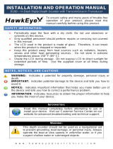
To mount the transducer on a transom:
1. Positionthetransducermountattheselectedtransom
location.Makesurethetransducerisparallelwiththewater
line.Markthecenterlocationsofeachholeonthetransducer
mount.
2. Usinga5/32"bit,drillthepilotholesapproximately1"
(25mm)deepatthemarkedlocations.Toavoiddrillingthe
holestoodeep,wrapapieceoftapearoundthebitat1"from
thepointofthebit.
3. Applymarinesealanttothe5x30mmscrews.Attachthe
transducerassemblytothetransomusingthe5x30mm
screws.Adjustthetransducerassemblytoextendbeyond
thebottomofthetransomapproximately1/8"(3mm)on
berglasshullsor3/8"(10mm)onaluminumhulls.Adjustthe
transducerassemblytobealignedparallelwiththewater.
4. Tightenthe10-32lockingnutuntilittouchesthemounting
bracket,andthentighten1/4turnmore.(Donotovertighten.)
5. Placetherstcableclamponthetransducercable
approximatelyonethirdofthedistancebetweenthe
transducerandthetopofthetransom.
Fishnder 400C Owner’s Manual
InstallIng the FIshFInder 400c
6. Markthelocation.Usinga1/8"bit,drillapilothole
approximately3/8"(10mm)deep.
7. Attachthecableclampusinga4x12mmscrew.Coatthe
screwwithmarinesealantbeforeinstallation.Repeatsteps5
and6usingtheothercableclamp.
8. Routethetransducercable,asneeded,totheshnder.DO
NOTCUTTHECABLE.Avoidroutingthecablewithelectrical
wiresorothersourcesofelectricalinterference.
OK
Level
Drill pilot holes here.
Vertical
Bottom of the transom
Align with the transom
bottom. The transducer
should extend /"
below berglass hulls
or /" below aluminum
hulls.
Keep it parallel with the water line.
Shoot-Thru-Hull Installation
To avoid drilling a hole to mount a thru-hull transducer, a
transducer can be secured with epoxy inside a boat (shoot-thru-
hull installation). This type of installation can provide better
noise reduction and allow you to use a higher Gain setting. For
a transducer to be mounted inside the hull (shoot-thru, not thru-
hull), the boat must be berglass, with no core. Contact your boat
manufacturer if you are unsure. Professional installation might be
necessary.
Some transducers are specically designed to be mounted inside a
berglass hull. The standard plastic transom mount transducer can
also be mounted using this method. If using a temperature sensing
transducer, the temperature shown reects the hull temperature.
Fishnder 400C Owner’s Manual
InstallIng the FIshFInder 400c
Selecting a Location for a Shoot-Thru-Hull Installation
When installing a transducer, the installation location must be the
following:
Solid berglass, without any air bubbles, laminates, llers, or
dead air space.
In an area of clean (non-turbulent) water at all speeds.
The location must not be over any strakes or behind any
obstruction on the hull that would create turbulence.
NOTE: Many modern hulls have a dedicated pocket for
shoot-thru-hull transducer installation. If you are unsure if your
hull is equipped with a pre-located pocket, contact your hull
manufacturer.
To test the location:
1. FabricateatestdevicefromasectionofPVCpipeoracan,
asshowninthefollowingillustration.
2. Temporarilysealthetestdevicetothehullwithcaulkingor
RTVsealer,andllwithwaterorlightmineraloil.
3. Placethetransducerinthewater,pointeddirectlyat
thebottomandweightitdown.Settheunitforoptimum
performance.Ifthesonarperformanceissignicantly
degraded,anotherlocationmustbetested.
Testing the Location
PVC pipe
or a can
Weight the transducer
to hold it in place.
Fill a pipe or can with
water or a light mineral oil.
Hull surface
Strip caulk or
RTV sealer
To permanently install the transducer:
1. Lightlysandthesurfaceofthehullandfaceofthetransducer
with400gritwetordrysandpaper.
2. Buildadamusingstripcaulkabout1/4"(6mm)tall.Pour
about1/8"(3mm)oftwo-part,slow-cureepoxyintothedam.
3. Placethetransducerintheepoxy,turningthetransducerto
workoutanyairbubbles.
4. Weightthetransducerinplace,andallowittocurefor
24hours.
0 Fishnder 400C Owner’s Manual
InstallIng the FIshFInder 400c
Step 4: Install the Wiring Harness
The Fishnder 400C comes with a wiring harness that connects
the shnder to power and the transducer with one easy-to-remove
connection and provides interface capabilities for connecting
external devices.
The color code in the diagram (see
page 11) indicates the appropriate
harness connections. The replacement fuse is a AGC/ 3AG - 3 Amp
fuse. If it is necessary to extend the power wires, use 22 AWG wire.
DO NOT cut the transducer cable, because this voids your warranty.
If your boat has an electrical system, you might be able to wire the
shnder directly to an unused holder on your current fuse block. If
you are using the boat’s fuse block, remove the in-line fuse holder
supplied with the shnder. You can also wire the shnder directly
to the battery.
CAUTION: The Fishnder 400C maximum input voltage is 35
Volts DC. Do not exceed this voltage, because this can damage
the Fishnder 400C and void the warranty.
NOTE: During a typical installation, use only the Red and Black
wires. The other wires do not have to be connected for normal
operation of the Fishnder 400C unit. For information on connecting
to a NMEA or CANet compatible device, see page 12.
To install the wiring harness:
1. Useatestlightorvoltmetertodeterminethepolarityofthe
voltagesource.
2. ConnecttheRed(+orpositive)wiretothepositivevoltage
terminal.(Ifyouusetheboat’sfuseblock,routethepositive
connectionthroughthefuse,asshownonthediagram.)
3. ConnecttheBlack(-orground)wiretothenegativevoltage
terminal.
4. Installorcheckthe3-Ampfuse(ontheboat’sfuseblockorin
thein-lineholder).
5. Alignthenotchesonthecableplugandonthebackofthe
shnder.Insertthecableintotheconnector,andturnthe
lockringcounter-clockwiseuntilitstops.
+
To 0- Volt boat supply
2A
-
+
Boat ground
-Amp
fuse
To Fishnder 400C
Fuse block
Fishnder 400C Owner’s Manual
InstallIng the FIshFInder 400c
CANet H
CANet L
DC Power
Source
Fishnder 400C Wiring Harness
PIN 8 - Black (Ground)
PIN 13 - Red (DC Positive)
PIN 7 - Yellow (Alarm)
PIN 12 - White (CANet H)
PIN 16 - Green (CANet L)
PIN 18 - Blue (NMEA Out)
Fishnder 400C Pin Assignment
 Fishnder 400C Owner’s Manual
InstallIng the FIshFInder 400c
Connecting to a NMEA device
You can connect the Fishnder 400C to another piece of NMEA
compatible electronic equipment, such as a Garmin GPS (Global
Positioning System) device. If equipped with a capable transducer,
the Fishnder 400C can send depth, temperature, and speed
information. Refer to the wiring diagrams on page 11 for connecting
the Fishnder 400C to NMEA compatible devices.
To install the wiring harness to a GPS or other NMEA
device:
1. Followthevoltagesourceinstallationsteps(seepage10).
ForGarminunits,theground(Black)wiresserveasNMEA
groundandmustbeattachedtogetheroronthesame
terminal.RefertothewiringdiagramofyourGPSunitfor
wireidentication.
2. ConnecttheBlue(NMEAOut)wirefromtheFishnder400C
totheNMEAInwireontheGPS/NMEAunit’swiringharness.
3. TurnontheFishnder400CNMEA Outputsetting(page23).
ForGarminGPSunits,setthecommunicationsinterfaceto
NMEA/NMEA,NMEA In/NMEA Out,orNMEA.
Interfacing with NMEA
The Fishnder 400C allows for NMEA 0183, Version 3.01 output
with a compatible GPS or navigation device. You must set NMEA
Output On to send data (page 23).
The SDDBT, SDDPT, SDMTW, SDVHW, SDWPL sentences are
sent in NMEA 0183, Version 3.01 output from the Fishnder 400C.
You can purchase complete information about National Marine
Electronics Association (NMEA) format and sentences from:
NMEA
Seven Riggs Avenue
Severna Park, MD 21146 USA
www.nmea.org
Installing the Fishnder 400C to a Garmin CANet
The Fishnder 400C is a CANet-compatible sonar device.
Using the CANet (if applicable) optimizes the performance of
CANet-compatible units, allowing sonar information from the
Fishnder 400C to be shared with up to two CANet compatible
Garmin GPS units. A standard NMEA connection only allows
depth, temperature, and speed information to be sent to a single GPS
device, whereas a CANet connection provides full sonar readings,
including Ultrascroll
, so you can view and control the same
information on your compatible GPS unit(s) as you can on your
Fishnder 400C.
NOTE: To use the Garmin CANet with your Fishnder 400C,
you must obtain a CANet Kit. Contact your Garmin dealer, or
visit www.garmin.com.
Fishnder 400C Owner’s Manual 
InstallIng the FIshFInder 400c
Step 5: Test the Installation
To turn on your Fishnder 400C for the rst time, press and hold the POWER key until the unit beeps and turns on. Use the ROCKER
and the SELECT key and follow the screens to congure your Fishnder 400C.
NOTE: Although it is possible to perform some checks with the boat trailered, the boat should be in the water to properly test the installation.
To congure your Fishnder 400C for the rst time:
Selectalanguage.
Selectatransducer
type.
Selectunitsof
measure.
Select a color
scheme.
The Home screen appears after you select your conguration options. After 15 seconds of inactivity, the shnder automatically switches to
Full Screen.
NOTE: If the transducer is not detected, a “Transducer Disconnected, Sonar Turned Off” message appears.
4 Fishnder 400C Owner’s Manual
InstallIng the FIshFInder 400c
Because water is necessary to carry the sounders sonar signal, the
transducer must be in the water to work properly. You cannot get a
depth or distance reading when out of the water.
When you place your boat in the water check for leaks around
any screw holes that were added below the water line. DO NOT
leave your boat in the water for an extended period of time without
checking for leaks.
To test the transom mount transducer installation:
1. Begintestingtheinstallationataslowspeed.Ifthesonar
appearstobeworkingproperly,graduallyincreasethe
boat’sspeedwhileobservingthesonar’soperation.Ifthe
sonarsignalissuddenlylostorthebottomreturnisseverely
degraded,notethespeedatwhichthisoccurs.
2.
Returntheboattothespeedatwhichthesignalwaslost.Make
moderateturnsinbothdirections,andseeifthesignalimproves.
3. Ifthesignalstrengthimproveswhileturning,adjustthe
transducersothatitextendsanother1/8"belowthetransom
oftheboat.Itmighttakeseveraladjustmentstoeliminatethe
degradation.
4. Ifthesignaldoesnotimprove,youmighthavetomovethe
transducertoadifferentlocation.
NOTE: When adjusting the depth of the transducer, make the
adjustments in small increments. Placing the transducer too
deep can adversely affect the boat’s performance and put the
transducer at greater risk of striking underwater objects.
  • Page 1 1
  • Page 2 2
  • Page 3 3
  • Page 4 4
  • Page 5 5
  • Page 6 6
  • Page 7 7
  • Page 8 8
  • Page 9 9
  • Page 10 10
  • Page 11 11
  • Page 12 12
  • Page 13 13
  • Page 14 14
  • Page 15 15
  • Page 16 16
  • Page 17 17
  • Page 18 18
  • Page 19 19
  • Page 20 20
  • Page 21 21
  • Page 22 22
  • Page 23 23
  • Page 24 24
  • Page 25 25
  • Page 26 26
  • Page 27 27
  • Page 28 28
  • Page 29 29
  • Page 30 30
  • Page 31 31
  • Page 32 32
  • Page 33 33
  • Page 34 34
  • Page 35 35
  • Page 36 36
  • Page 37 37
  • Page 38 38
  • Page 39 39
  • Page 40 40

Garmin 400C User manual

Category
Navigators
Type
User manual
This manual is also suitable for

Ask a question and I''ll find the answer in the document

Finding information in a document is now easier with AI