
REV 004A
High
Quality
Nautical
Equipment
Manuale d'uso PULSANTIERA MULTIUSO HRC
User's Manual HRC MULTIPURPOSE CONTROL PANEL
Manuel de l'utilisateur BOITIER DE COMMANDE MULTI-USAGE HRC
Benutzerhandbuch MEHRZWECK-FERNBEDIENUNG HRC
Manual del usuario TABLERO DE PULSADORES MULTIUSO HRC
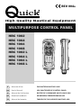
MULTIPURPOSE CONTROL PANEL
HRC 1002
HRC 1004
HRC 1006
HRC 1008
HRC 1002 L
HRC 1004 L
HRC 1006 L
HRC 1008 L
IT
GB
FR
DE
ES
Page is loading ...

3
HRC - REV004A
Pag. 4 Caratteristiche e Installazione - installazione della presa
Pag. 5 Installazione - installazione della presa
Pag. 6 Installazione - Supporto
Pag. 7 Installazione - Supporto
Pag. 8 Installazione / Funzionamento - personalizzazione della pulsantiera
- connessione alla presa
Pag. 9 Installazione - schemi di collegamento
Pag. 10 Funzionamento - accensione e spegnimento della torcia
Pag. 11 Manutenzione / Caratteristiche tecniche
INDICE
Pg. 12 Characteristics and installation - installing the socket
Pg. 13 Installation - installing the socket
Pg. 14 Installation - Support
Pg. 15 Installation - Support
Pg. 16 Installation / Operating - personalizing the control panel
- connecting to the socket
Pg. 17 Installation - connection diagrams
Pg. 18 Operating - switching the torch on and off
Pg. 19 Maintenance / Technical data
P. 20 Caractéristiques et installation - installation de la prise
P. 21 Installation - installation de la prise
P. 22 Installation - Support
P. 23 Installation - Support
P. 24 Installation / Fonctionnement - personnalisation du boitier de commande
- connexion du boîtier de commande à la prise
P. 25 Installation - schémas de branchement
P. 26 Fonctionnement - allumage et extinction de la torche
P. 27 Entretien / Caractéristiques techniques
SOMMAIRE
S. 28 Eigenschaften und Installation - Installation der Steckdose
S. 29 Installation - Installation der Steckdose
S. 30 Installation - Halterung
S. 31 Installation - Halterung
S. 32 Installation / Betrieb - Personaliche gestaltung der Fernbedienung
- Anschluss der Fernbedienung an die Steckdose
S. 33 Installation - Anschlusstafeln
S. 34 Betrieb - Anschluss und Ausschalten der Lampe
S. 35 Wartung / Technische daten
INHALTSANGABE
Pág. 36 Características e Instalación - instalación de la toma
Pág. 37 Instalación - instalación de la toma
Pág. 38 Instalación - Soporte
Pág. 39 Instalación - Soporte
Pág. 40 Instalación / Funcionamiento - personalización del tablero de pulsadores
- conexión del tablero de pulsadores en la toma
Pág. 41 Instalación - esquema de conexión
Pág. 42 Funcionamiento - prender y apagar la antorcha
Pág. 43 Mantenimiento / Especifi caciones técnicas
INDICE
INDEX
IT
GB
FR
DE
ES
Page is loading ...
Page is loading ...
Page is loading ...
Page is loading ...
Page is loading ...
Page is loading ...
Page is loading ...
Page is loading ...

12
GB
HRC - REV004A
MULTIPURPOSE CONTROL PANEL
The Quick
®
multipurpose control panel is an instrument designed for the remote control of various moving
systems on board a boat, including mini-crane, gangplank, swimming ladder, anchor hoist.
INSTALLATION
BEFORE USING THE INSTRUMENT PLEASE STUDY THIS USER MANUAL. IN CASE OF ANY
DOUBT PLEASE CONTACT THE RETAILER OR QUICK
®
CUSTOMER SERVICE.
In case of discordance or errors in translation between the translated version and the original text in
the Italian language, reference will be made to the Italian or English text.
This device was designed and constructed for use on recreational crafts.
Other forms of use are not permitted without written authorization from the company Quick
®
.
The control was designed for the purposes described in this user manual. The company Quick
®
does
not accept any responsibility for direct or indirect damage caused by the improper use of the device, by
incorrect installation, or for any errors in this user manual.
WARNING: the electrical appliance controlled by the control panel must be provided with safety
systems to prevent damage to persons, things, or the environment that might result from the
defective operation of the control panel.
THE OPENING OF THE INSTRUMENT BY UNAUTHORIZED PERSONNEL MAKES THE
WARRANTY VOID.
THE PACKAGE CONTAINS:
control panel - support - socket - socket seal and cover - screws - drilling
template - personalised adhesives (only in certain models) - the present manual of use.
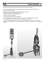
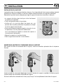
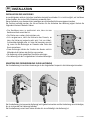
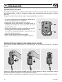
FITTING THE SOCKET
A typical installation procedure is described below.
It is not possible to define a single procedure that is applicable in every situation.
Adapt the procedure described here to your own requirements.
Identify the most appropriate position for the socket seating on the basis of the following criteria:
• The socket must be positioned so that it can easily be reached by the operator.
• Choose a clean, smooth, flat location.
• Rear access is required for installation and maintenance.
• There must be sufficient space behind the chosen position for the passage of the socket cable.
• The back of the socket must not be exposed to contact with water or humidity.
• Take particular attention when drilling the panels or parts of the boat. The holes must not weaken or
cause the breakage of structural elements of the boat.
CHARACTERISTICS AND INSTALLATION
F
F

13
GB
HRC - REV004A
After choosing where to position the instrument, proceed as follows:
• Position the drilling template (provided) on the surface where the socket will be installed.
• Mark the centre of each hole.
• Create the hole for the passage of the socket cable with a milling cutter.
• Remove the template and any splinters around the hole.
• Fit the seal to the socket base.
• Put the cable through the hole created.
• Fix the socket in position with the 4 screws provided.
• Before making the electrical connections ensure that the electrical supply is not connected.
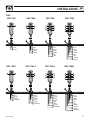
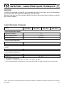
• For the connection of the electrical wires refer to the wire colouring as in fig. 1.
• Insert a fast-acting fuse of 200mA on the torch supply line (wires A and B, if present).
• Before switching on the power to the control, check that all the electrical connections are correct.
INSTALLATION
UP DOWN
LEFT RIGHT

14
GB
HRC - REV004A
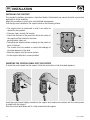
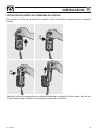
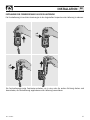
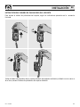
INSTALLING THE SUPPORT
The standard installation procedure is described below. Unfortunately we cannot describe a procedure
applicable to all the situations.
Adapt this procedure to satisfy your own individual requirements.
Find the spot most suitable for the support based on the following criteria:
• The support must be positioned so that it can easily be
reached by the operator.
• Choose a clean, smooth, flat location.
• Check that the back of the panel into which the screws of
the support will be inserted is free from
passing cables, tubes, etc.
• Take particular attention when screwing into the panels or
parts of the boat.
The screws must not weaken or cause the breakage of
structural elements of the boat.
• Place the support onto the chosen surface.
• Fix the support with the 2 screws provided.
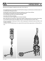
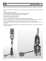
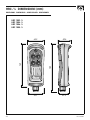
INSERTING THE CONTROL PANEL INTO THE SUPPORT
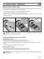
To insert the control panel into the support, follow the instructions in the illustrated sequence:
Insert the control panel slightly rotated into the support and continue the rotation until the control panel
is parallel with the support.
Push the control panel down until it is fully inserted into the support.
INSTALLATION

15
GB
HRC - REV004A
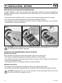
EXTRACTING THE CONTROL PANEL FROM THE SUPPORT
To extract the control panel from the support, follow the instructions in the illustrated sequence:
Slide the control panel from its support by raising it a few centimetres, rotate in either direction and then
extract it from the support by raising it.
INSTALLATION

16
GB
HRC - REV004A
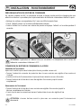
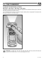
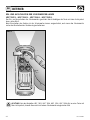
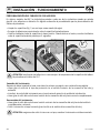
WARNING: the application of adhesives is not recommended if the temperature of the
surface of the control panel is below 10°C.
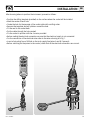
CONNECTING THE CONTROL PANEL TO THE SOCKET
Connecting the instrument
After installing the socket as described above, proceed as follows:
• Rotate the ring-nut of the protective cover anticlockwise and remove it.
• Insert the instrument plug into the relevant socket, taking care that the position of insertion is
correct.
• Turn the plug locking ring-nut clockwise until fully closed.
Disconnecting the instrument
• Turn the plug locking ring-nut anticlockwise until fully open and remove.
• Cover the socket with the cover provided, turning the ring-nut clockwise.
WARNING: always ensure that the socket is closed with the cover provided when the instrument
is disconnected.
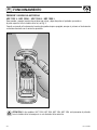
PERSONALIZING THE CONTROL PANEL
In some HRC models the symbols on the individual keys can be changed by applying the stickers provided.
The procedure for personalizing the control panel is as follows:
• Clean the relevant surfaces with a soft cloth dampened with water (fig. 1).
• Choose a sticker for application to the surface cleaned previously.
• Centre the sticker on the surface without applying pressure and then press it down on the
surface for 5 seconds.
FIG.1
5"
INSTALLATION - OPERATING

17
GB
HRC - REV004A
1
2
A
B
1
2
3
4
A
B
1
2
3
4
5
6
7
8
A
B
1
2
3
2
4
2
4
6
8
2
4
6
1
3
1
3
5
7
1
3
5
4
5
6
A
B
21
1
2
3
4
5
6
1
2
1
2
3
4
1
2
3
4
5
6
7
8
2
2
4
2
4
6
8
2
4
6
1
1
3
1
3
5
7
1
3
5
HRC 1002 HRC 1004 HRC 1006 HRC 1008
BROWN ROUND
BLUE
BLACK
WHITE
GREEN
RED
GREY
ORANGE
YELLOW
BROWN ROUND
BLUE
BLACK
WHITE
GREEN
RED
GREY
BROWN ROUND
BLUE
BLACK
WHITE
GREEN
BROWN ROUND
BLUE
BLACK
BROWN ROUND
BLUE
BLACK
WHITE
GREEN
RED
GREY
ORANGE
YELLOW
PURPLE
TURQUOISE
PURPLE
TURQUOISE
BROWN ROUND
BLUE
BLACK
WHITE
GREEN
RED
GREY
PURPLE
TURQUOISE
BROWN ROUND
BLUE
BLACK
WHITE
GREEN
PURPLE
TURQUOISE
BROWN ROUND
BLUE
BLACK
HRC 1002 L HRC 1004 L HRC 1006 L HRC 1008 L
FIG.2
INSTALLATION

18
GB
HRC - REV004A
WARNING: models HRC 1002, HRC 1004, HRC 1006, HRC 1008 have the button with the light sym-
bol even though they are not equipped with a torch.
SWITCHING THE TORCH ON AND OFF
HRC 1002 L - HRC 1004 L - HRC 1006 L - HRC 1008 L
The torch is switched on and off by pressing and releasing the button at the top with the light
symbol, see fig. 3. When the instrument is first switched on the torch is always off, even if previously
disconnected from the supply with the torch on.
FIG.3
OPERATING

19
GB
HRC - REV004A
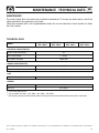
MODEL
HRC 1002 HRC1004 HRC 1006 HRC 1008
HRC 1002 L HRC 1004 L HRC 1006 L HRC 1008 L
ELECTRICAL CHARACTERISTICS
Current capacity of contacts
(1)
Torch supply voltage
(2)
Torch power absorption
(2)
4A
6 ÷ 30 Vdc
100mA Max
4.2 m
EN 55022/B
GENERAL
Maximum cable extension
EMC class
62.2 x 185 x 49.4 mm
CASE
Dimensions (LxHxD)
-15 ÷ +70 °C
IP 67
AMBIENT CHARACTERISTICS
Operating temperature
Protection rating
(3)
(1)
On resistive load at 30 Vdc.
(2)
Only on models HRC 1002 L - HRC 1004 L - HRC 1006 L - HRC 1008 L.
(3)
With the plug correctly inserted into the socket. Excluding the area of the socket where the exit cable is fixed (IP 00).
TECHNICAL DATA
QUICK
®
RESERVES THE RIGHT TO MODIFY THE TECHNICAL CHARACTERISTICS OF THE EQUIPMENT AND THE CONTENTS OF THIS MANUAL WITHOUT PRIOR NOTICE.
MAINTENANCE
The control panel does not require any particular maintenance. To assure top performance, check the
cables and electrical connections once a year.
Clean the instrument with a soft rag dampened in water. Do not use chemicals or harsh products to clean
the chain counter.
MAINTENANCE - TECHNICAL DATA
Page is loading ...
Page is loading ...
Page is loading ...
Page is loading ...
Page is loading ...
Page is loading ...
Page is loading ...

27
FR
HRC - REV004A
MODÈLE
HRC 1002 HRC1004 HRC 1006 HRC 1008
HRC 1002 L HRC 1004 L HRC 1006 L HRC 1008 L
CARACTÉRISTIQUES ELECTRIQUES
Charge maxi des contacts
(1)
Tension alimentation torche
(2)
Consommation torche
(2)
4A
6 ÷ 30 Vdc
100mA Max
4.2 m
EN 55022/B
CARACTERISTIQUES GENERALES
Extension maximum du câble
Catégorie EMC
62.2 x 185 x 49.4 mm
COFFRET
Dimensions (LxHxP)
-15 ÷ +70 °C
IP 67
CARACTERISTIQUES AMBIANTES
Température de service
Degré de protection
(3)
(1)
Surcharge résistive sous 30 Vdc.
(2)
Uniquement sur les modèles HRC 1002 L - HRC 1004 L - HRC 1006 L - HRC 1008 L.
(3)
Avec la fiche correctement introduite dans la prise. La zone de la prise où est soudé le câble de sortie est exclue (IP 00).
CARACTÉRISTIQUES TECHNIQUES
LA QUICK
®
SE RÉSERVE LE DROIT D'APPORTER DES MODIFICATIONS AUX CARACTÉRISTIQUES TECHNIQUES DE L'INSTRUMENT ET AU CONTENU DE CE MODE D'EMPLOI SANS AUCUN PRÉAVIS.
ENTRETIEN
Le boitier de commande ne nécessite aucun entretien particulier. Pour garantir un bon fonctionnement,
contrôler les câbles et les connexions électriques toutes les années.
Nettoyer l'écran avec un chiffon moelleux imbibé d'eau. Ne pas utiliser des produits chimiques ou abrasifs
pour nettoyer l'appareil.
ENTRETIEN - CARACTÉRISTIQUES TECHNIQUES
Page is loading ...
Page is loading ...
Page is loading ...
Page is loading ...
Page is loading ...
Page is loading ...
Page is loading ...
Page is loading ...
Page is loading ...
Page is loading ...
Page is loading ...
Page is loading ...
Page is loading ...
Page is loading ...
Page is loading ...
Page is loading ...
Page is loading ...
Page is loading ...
Page is loading ...
Page is loading ...

QUICK
®
SRL - Via Piangipane, 120/A - 48124 Piangipane (RAVENNA) - ITALY
Tel. +39.0544.415061 - Fax +39.0544.415047
www.quickitaly.com - E-mail: quick@quickitaly.com
R004A
Codice e numero seriale del prodotto
Product code and serial number
Code et numéro de série du produit
Code- und Seriennummer des Produkts
Código y número de serie del producto
GB
FR
DE
IT
ES
HRC 1002/1008
MULTIPURPOSE CONTROL PANEL
-
 1
1
-
 2
2
-
 3
3
-
 4
4
-
 5
5
-
 6
6
-
 7
7
-
 8
8
-
 9
9
-
 10
10
-
 11
11
-
 12
12
-
 13
13
-
 14
14
-
 15
15
-
 16
16
-
 17
17
-
 18
18
-
 19
19
-
 20
20
-
 21
21
-
 22
22
-
 23
23
-
 24
24
-
 25
25
-
 26
26
-
 27
27
-
 28
28
-
 29
29
-
 30
30
-
 31
31
-
 32
32
-
 33
33
-
 34
34
-
 35
35
-
 36
36
-
 37
37
-
 38
38
-
 39
39
-
 40
40
-
 41
41
-
 42
42
-
 43
43
-
 44
44
-
 45
45
-
 46
46
-
 47
47
-
 48
48


Quick HRC 1002 User manual
- Type
- User manual
Ask a question and I''ll find the answer in the document
Finding information in a document is now easier with AI
in other languages
- italiano: Quick HRC 1002 Manuale utente
- français: Quick HRC 1002 Manuel utilisateur
- español: Quick HRC 1002 Manual de usuario
- Deutsch: Quick HRC 1002 Benutzerhandbuch
Related papers
-
Quick HR5 1724 DC series User manual
-
Quick HC3 1012 D User manual
-
-
-
-
-
-
-
-
Other documents
-
Bticino HS4261C6 Operating instructions
-
-
DOMUS LINE CALL ME User manual
-
Team Losi Racing TLR03017 Owner's manual
-
Eaton EASY800-MO-CAB Operating instructions
-
SPORTSTECH F38 User manual
-
Tunturi T50 Owner's manual
-
-
-