
1
© 2019 Midmark Corp. | 60 Vista Drive Versailles, OH 45380 USA | 1-800-643-6275 | 1-937-526-3662 |
003-2924-00 Rev. AA5 (9/25/19)
Applies to Models:
M9 (-040 /-041 / -042 /-043)
M9D (-042)
M11 (-040 /-041/ -042/-043)
Special Tools:
none
Language of origin: English
M9/M11 Thermal Printer Installation (9A599001)
TP201 20-42-FO-00013 Rev A1 C2169
Thermal Printer
WARNING
Disconnect all electrical power to the unit before removing
any of the unit’s covers or making any repairs to prevent
possibility of electrical shock. Failure to comply with these instructions
could result in serious personal injury.
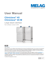
Step 1: Remove Cover
A) Unplug sterilizer power cord.
B) Using a flat-bladed screwdriver, pry cover up from the front
edge, then remove.
C) Locate printer harness, remove tape securing wires to the
bottom of the printer cavity.
Printer
Harness
Cover
Style G
midmark.com

2
Clear Film
(Hook and Loop)
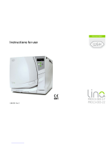
Step 2: Attach Wires/Remove Film
A) Position the printer upside down with the the long hook and loop strip
facing you.
B) Take the black/red harness, position the white wire connection tabs
downward and connect to the left side of the printer.
C) Take the green/white/black harness, position the white wire connection
tabs downward and connect to the right hand side of the printer.
D) Peel off the clear film of the long hook and loop strip to expose sticky
side of the hook and loop.
Note: Push connectors into place firmly almost flush with the printer.
Printer
Harness
Step 3: Install Printer
A) To align the printer correctly in the printer cavity, tilt up the front edge of the
printer, position the back edge of the printer on the top back edge of the
printer cavity.
B) Keep the back edge of the printer in position and remove the clear film
from the two small hook and loop sections on the front of the printer.
C) Pivot the front edge of the printer down into position in the printer cavity.
Press firmly into place.
Equipment Alert
Position printer harness into printer cavity making sure it is not pinched or
kinked by the printer
.
Align Back
Edge
Printer
Harness
Clear Film
(Hook and Loop)
003-2924-00

3
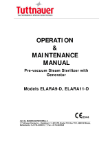
Paper Roll Removal / Installation
Equipment Alert
Use only thermal paper rolls with a maximum diameter of 1.89” (48 mm)
and width of 2.28” (58 mm).
To remove paper...
A) Insert finger into groove at the back of the small cover and lift upward until
lid is released from locked position. To avoid damage do not use excessive
force.
B) The printer lid will hinge up towards the back of the printer.
C) Remove any remaining paper.
To install the paper roll...
A) Unroll 3” to 4” (5 to 7.5 cm) of paper.
B) Place the paper roll into cradle, unrolled side down.
C) Hold unrolled edge of paper out the front of the printer and shut the lid by
applying equal amounts of pressure on each side of lid until it latches.
D) Press the paper feed button for additional paper.
Note
A pink stripe that gets progressively darker on the paper indicates when paper is low.
Printer Paper Rell
(2.28” Wide X 1.88”Dia. Max)
Order Number Roll
Length
Printer Thermal Paper Roll 060-0016-00 85’
Printer Stick-able Thermal Paper 060-0016-01 60’
SA1841i
Status Light
Paper Feed Button
Paper Slot
Printer Housing
PRINTER TROUBLESHOOTING
Status Light Condition Solution
On Printer On -
O Printer O -
Paper out or door open Fill Paper / Shut Door
Thermal Head too hot Allow head to cool
003-2924-00

4
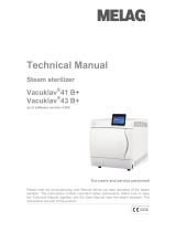
Printer Tape Description
The printer will print the following information for each program cycle:
• Model Number: indicates sterilizer model and software version.
• Cycle Number: reects actual cycle count of sterilizer.
• Sterilizer ID: Serial Number of sterilizer.
• Operator: a line is printed so the operator’s signature can be recorded on
the printer tape.
• Date Time: of start of each cycle
• “BEGIN selected CYCLE”: to indicate the beginning of the cycle selected
by the operator.
• Summary of selected cycle set points.
Once the cycle starts, the printer will print the words “FILLING CHAMBER” to show
that the sterilizer is ling with water.
Once the sterilizer begins the Heating Phase of the sterilization cycle, the word
“HEATING” is printed and the printer will print the chamber temperature, pressure,
and elapsed time in 2 minute increments until the heating phase is completed.
When the sterilizer enters the sterilization phase, the word “STERILIZING” is
printed and the printer will print the chamber temperature, pressure, and elapsed
time in 1 minute increments until the sterilization phase is completed.
When the sterilizer has completed the sterilization phase of the program cycle, the
printer will print the words “VENTING CHAMBER” to show that the steam pressure
is being exhausted from the chamber.
When the sterilizer enters the drying phase, the word “DRYING” is printed and the
printer will print the words “DRYING START” and show temperature, pressure, and
elapsed time in 5 minute increments starting with 5:00. The printer continues to
print the elapsed time in 5 minute increments until the drying phase is completed.
The nal record for the drying phase will include the words “DRYING COMPLETE”.
In the event the drying time is programmed to a time that isn’t divisible by 5, the
nal printed record for the drying phase will reect the actual programmed drying
time in 1 minute increments, e.g. a programmed dry time of 12 minutes will have
5,10,and 12 minutes printed on the printer tape.
When the sterilizer has completed the drying phase of the sterilization cycle, the
printer will print a summary of the sterilization cycle with the duration of each phase
of the cycle and the Total Cycle Time. Following the summary the printer will print
“CYCLE COMPLETE”.
[NOTE: If drying cycle is aborted, “DRYING COMPLETE” and “CYCLE
COMPLETE” will not print].
Midmark M9 - v0.1.1
Total Cycles: 10
Sterilizer ID: V0000000
Operator
1/27/2016 8:08 AM
BEGIN UNWRAPPED CYCLE
Temp: 270
Degrees F
Time: 3 Minutes
Dry: 30
Minutes
FILLING CHAMBER
HEATING
mm:ss Degrees PSI
0:00 77.2F 0.0
2:00 82.7F 0.7
4:00 152.2F 5.4
STERILIZING
mm:ss Degrees PSI
0:00 272.1 F 28.0
1:00 273.0 F 28.7
2:00 272.2 F 27.9
3:00 272.4 F 28.7
Min 272.0 F 27.9
Max 273.1 F 29.0
VENTING CHAMBER
DRYING
Drying Start
mm:ss Degrees PSI
5:00 192.8 F 0.0
10:00 192.7 F 0.0
30:00 192.8 F 0.0
Drying Complete
FILLING: 0:36
HEATING: 15:40
STERILIZING: 3:00
VENTING: 2:28
DRYING: 30:00
TOTAL CYCLE 00:51:44
CYCLE COMPLETE
--------------------------------------------
Sterilizer Identication
(Serial Number)
Total # of cycles
run on unit
Line provided for
operator signature
Date and Time
of cycle start
Selected Cycle
Indicates Filling
phase initiated
Sterilization temperature,
time, and dry time settings
During Heat-Up phase, the
printer records chamber
temperature and pressure
in 2 minute increments
During Sterilization phase,
the printer records chamber
temperature and pressure in
1 minute increments
Summary of
Sterilization phase
Indicates Venting
phase initiated
During Drying phase,
the printer records time in
5-minute increments
These lines will show the
total dry time completed
Cycle summary
Model # and
Software Version
These lines will not
print if Dry Cycle
is aborted before it
completes
003-2924-00
-
 1
1
-
 2
2
-
 3
3
-
 4
4


Midmark M9/M11 Self -Contained Steam Sterilizer (-043) Installation guide
- Type
- Installation guide
- This manual is also suitable for
Ask a question and I''ll find the answer in the document
Finding information in a document is now easier with AI
Related papers
-
Midmark M3 Steam Sterilizer User guide
-
Midmark M11-041 User manual
-
Midmark M9/M9D, M11 Self-Contained Steam Sterilizer (-040 through -042) User guide
-
-
Midmark UltraClave M11 Installation & Operation Manual
-
-
-
-
Midmark LED Dental Light Installation guide
-
Other documents
-
SciCan BRAVO User manual
-
 MELAG Cliniclave 45 User manual
-
-
Benchmark Scientific B4000-16 Owner's manual
-
 LiNA PRO13-003-17 Instructions For Use Manual
-
3M Steri-Vac™ Sterilizer / Aerator GS8-1D Operating instructions
-
 Tuttnauer ELARA11-D Operation & Maintenance Manual
-
-
 MELAG Vacuklav 41 B Plus Evolution Technical Manual
-


