Installation instructions
Induction glass ceramic hob
With normal mounting frame
J488.113-2
20.1.09 ITH
1
These installation instructions apply to the models: 488 (GK46TIC), 489 (GK46TIVC), 002 (GK46TIASC)
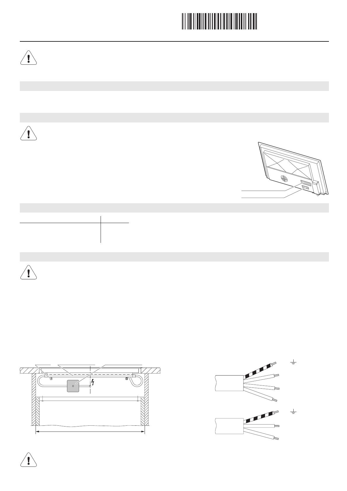
Identification plate
The identification plate is next to the connection plate.
A Affix the second identification plate (enclosed) in an accessible position behind the front
of the fitted cabinet beneath the appliance.
A Information on the necessary mains voltage, type of current and fuse protection is to be obtained from the identification plate.
A The appliance is equipped with a mains cable that should be connected to a distribution box by the customer.
A If an oven is installed beneath the appliance, we recommend placing the distribution box behind the base. A cut-out can be made
in the rear wall for the cables.
Error message U400
The appliance should be installed by qualified personnel only. Each step must be carried out and checked in full in the order
specified.
Validity
General notes
If fitting in flammable material, the guidelines and standards for low voltage installations and for the fire protection must be strict-
ly observed.
Accessories
Designation Article no.
Ventilation protective plate set
For niche width 550–600 mm
For niche width 825–900 mm
H6.2122
H6.2123
Electrical connections
Electrical connections must be carried out by trained electricians in accordance with the guidelines and standards for low volt-
age installations and the specifications of the local electricity supply companies.
A plug-in appliance may only be connected to a socket outlet with earthing contact, installed according to specifications. A
mains isolating device with 3 mm contact opening should be provided in the house wiring system. Switches, plug and socket
devices, circuit breakers and fusible cut-outs which are accessible after installation and which have all-poles switching are per-
missible as isolating devices. Effective earthing and separately installed neutral and earth conductors ensure safe and fault-
free operation. After installation, live parts and cables with basic insulation must not be accessible. Old installations should al-
ways be checked.
Incorrect connection:
A pole conductor was connected to the connecting terminal for neutral conductors.
Quickly disconnect the appliance from the mains!
Connection plate
Identification plate
600/550
900
Installation pipe
Distribution box
Clamp
400 V 2N~
230 V~
AUS / NZ
PE/ green/yellow
N blue
L1 brown
L2 black
PE/ green/yellow
N blue
L1 brown

