Page is loading ...

waterpurification.pentair.com
FLECK 2510 AIO CONTROL VALVE
SERVICE MANUAL

2 • FLECK 2510 AIO SXT Service Manual
TABLE OF CONTENTS
JOB SPECIFICATION SHEET ...............................................2
VALVE SPECIFICATIONS ......................................................3
INSTALLATION .....................................................................4
DEFLECTOR INSTALLATION ...............................................4
REGENERATION STEPS ......................................................5
START-UP INSTRUCTIONS..................................................5
TIMER OPERATION .............................................................. 6
SXT USER PROGRAMMING .................................................7
DIAGNOSTIC PROGRAMMING MODE .................................. 7
2510 AIO SXT CONTROL VALVE ASSEMBLY .......................8
POWERHEAD ASSEMBLY .................................................. 10
2510 VALVE ACCESSORIES ...............................................12
2510 VALVE CONVERSION ASSEMBLIES ..........................13
BYPASS VALVE ASSEMBLY (PLASTIC) ..............................14
BYPASS VALVE ASSEMBLY (METAL) ................................15
TROUBLESHOOTING (2510) ...............................................16
TROUBLESHOOTING (AIO) .................................................17
FLOW DATA & INJECTOR DRAW RATES ..........................18
SXT WIRING DIAGRAM.......................................................19
JOB SPECIFICATION SHEET
Job Number: ______________________________________________
Model Number: ____________________________________________
Iron (ppm): ________________________________________________
Tank Size: ________________________________________________
1. Timer Program Settings:
A. Backwash: ______________________________ Minutes
B. Air Draw: _______________________________ Minutes
C. Rapid Rinse: ____________________________ Minutes

FLECK 2510 AIO SXT Service Manual • 3
IMPORTANT PLEASE READ:
• The information, specifications and illustrations in this manual are
based on the latest information available at the time of release. The
manufacturer reserves the right to make changes at any time without
notice.
• This manual is intended as a guide for service of the valve only. System
installation requires information from a number of suppliers not known
at the time of manufacture. This product should be installed by a
plumbing professional.
• This unit is designed to be installed on potable water systems only.
• This product must be installed in compliance with all state and
municipal plumbing and electrical codes. Permits may be required at
the time of installation.
• It is established that when daytime water pressure exceeds 80 psi (5.5
bar), the maximum pressure rating of 125 psi (8.6 bar) can be exceeded.
A pressure regulator must be installed on this system or warranty is
voided.
• Do not install the unit where temperatures may drop below 32°F (0°C)
or above 120°F (52°C).
• Do not place the unit in direct sunlight. Black units will absorb radiant
heat, increasing internal temperatures.
• Do not strike the valve or any of the components.
• Warranty of this product extends to manufacturing defects.
Misapplication of this product may result in failure to properly condition
water, damage to product, or personal injury.
• A prefilter should be used on installations in which free solids are
present.
• In some applications local municipalities treat water with Chloramines.
High Chloramine levels may damage valve components.
• Correct and constant voltage must be supplied to the controller to
maintain proper function.
• The system is intended to treat only potable quality water. It is not
intended as the permanent primary treatment of water from a source
that is contaminated, such as from radon, pesticides, insecticides,
sewage or wastewater.
• This system is not intended for use by persons (including children) with
reduced physical, sensory, or mental capabilities, or lack of experience
and knowledge, unless they have been given supervision or instruction
concerning use of the appliance by a person responsible for their safety.
• Children shall not play with the system.
• Cleaning shall not be made by children without supervision.
VALVE SPECIFICATIONS
Valve Material Fiber-reinforced polymer
Inlet/Outlet 3/4”, 1”, or 1-1/4”
NPT/BSP/Sweat
Cycles 3 or 5
Flow Rates (50 psi inlet) valve only
Continuous
15 psi drop
19 GPM (4.3 m³/hr)
Peak
25 psi drop
25 GPM (5.5 m³/hr)
Cv
flow at 1 psi drop
4.8
Max Backwash
25 psi drop
17 GPM (3.9 m³/hr)
Dimensions
Distributor Pilot 1.05” O.D. (26.7 mm)
Drain Line 1/2” NPTF Quick-Connect
Injector System 1600, 1650
Mounting Base 2.5” - 8 NPSM
Height from Top of
Tank
7.5” (191 mm)
Riser Tube Diameter 3/4” (19 mm)
Riser Height 1/4” below top of tank
Additional Information
Electrical Rating 24/110/220V
50/60 Hz
Pressure (Hydrostatic) 300 psi
(20 bar)
Pressure (Working) 20-125 psi
(1.4-8.5 bar)
Temperature
Cold Water Valve:
34-110°F (1-43°C)
Deflector 1” inner diameter

4 • FLECK 2510 AIO SXT Service Manual
INSTALLATION
Installation Overview
The AIO valve is designed for use when water containing
contaminates subjected to oxidation is encountered. The
water passes through the AIO valve then passes through the
tank containing oxygen enriched filter media. The oxygen
reduces all contaminates in the water to an oxide, or in the
case of hydrogen sulfide gas, it is reduced to a molecule of
acid.
Install the AIO valve after the supply lines to the outside
faucets (unless outside faucets need to be free of
contaminates in water). The AIO valve is generally installed
before a water softener or any taste/odor cartridges, if
applicable.
Due to the release of air during regeneration, the drain line
should be anchored throughout the run and secured at the
end of the drain line. The drain line should be sized for the
backwash rate and friction loss.
The drain line flow control should accommodate the size
tank and backwash rate for the filter media being used.
The injector size (slow rinse rate based on pressure) should
be sized the same as the service flow rate of the filter media
being used.
Water Pressure
A minimum of 20 psi (1.4 bar) of water pressure is required
for regeneration valve to operate effectively.
CAUTION
Water pressure is not to exceed 125 psi (8.6 bar),
water temperature is not to exceed 110°F (43°C),
and the unit cannot be subjected to
freezing conditions.
Electrical Facilities
An uninterrupted alternating current (120 VAC) supply is
required. Please make sure your voltage supply is compatible
with your unit before installation.
NOTE: Other voltages are available. Please make sure your
voltage supply is compatible with your unit
before installation. The power source should be
constant. Be certain the power adapter is not on a
switched outlet.
Existing Plumbing
Condition of existing plumbing should be free from lime and
iron buildup. Piping that is built up heavily with lime and/
or iron should be replaced. If piping is clogged with iron,
a separate iron filter unit should be installed ahead of the
water softener.
Location Of Softener/Filter/AIO Drain
You must have an air gap on the drain line to prevent back
flow of drain water into the system. A 2x the drain line pipe
diameter air gap is required with a minimum 1” air gap.
Bypass Valves
Always provide for the installation of a bypass valve if unit is
not equipped with one.
Recommended Servicing
Due to the nature of AIO valves, it is recommended to replace
the injector, air check, piston, seals and spacers, and adapter
coupling every 6 to 12 months as needed.
WARNING:
The system MUST be depressurized before
removing any connections for servicing.
Installation Instructions
1. Place the softener tank where you want to install the unit
making sure the unit is level and on a firm base.
2. During cold weather, the installer should warm the valve to
room temperature before operating.
3. All plumbing should be done in accordance with local
plumbing codes. The pipe size for residential drain line
should be a minimum of 1/2 inch (13 mm). Backwash flow
rates in excess of 7 gpm (26.5 Lpm) or length in excess of 20
feet (6 m) require 3/4-inch (19 mm) drain line. Commercial
drain lines should be the same size as the drain line
flow control. Be sure drain lines are secured properly.
4. Refer to the dimensional drawing for cutting height of the
distributor tube. If there is no dimensional drawing, cut
the distributor tube flush with the top of the tank. The tank
should have the distributor tube installed and the proper
amount of regenerant in place.
5. Lubricate the distributor o-ring seal and tank o-ring seal.
Place the main control valve on tank.
NOTE: Only use silicone lubricant.
6. Solder joints near the drain must be done prior to
connecting the Drain Line Flow Control fitting (DLFC). Leave
at least 6 inches (15 cm) between the DLFC and solder
joints when soldering pipes that are connected on the DLFC.
Failure to do this could cause interior damage to the DLFC.
7. Plumber tape is the only sealant to be used on the drain
fitting.
8. On units with a bypass, place in bypass position. Turn on the
main water supply. Open a cold soft water tap nearby and let
run a few minutes or until the system is free from foreign
material (usually solder) that may have resulted from the
installation. Once clean, close the water tap.
9. Slowly place the bypass in service position and let water
flow into the mineral tank. When water flow stops, slowly
open a cold water tap nearby and let run until the air is
purged from the unit.
10. Plug unit into an electrical outlet.
NOTE: All electrical connections must be connected according
to local codes. Be certain the outlet is uninterrupted.
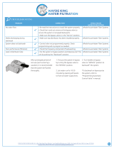
DEFLECTOR INSTALLATION
Put a thin layer of silicone lube around inside diameter of the
deflector. Slowly slide the deflector over the distributor tube
down about 1”. When threading the AIO valve to the tank, the
bottom of the threads will slide the deflector down, as shown
in the diagram.
Figure 1

FLECK 2510 AIO SXT Service Manual • 5
START-UP INSTRUCTIONS
The water softener should be installed with the inlet,
outlet, and drain connections made in accordance with the
manufacturer’s recommendations, and to meet applicable
plumbing codes.
1. Initiate a manual regeneration by pressing the Extra Cycle
button for 5 continuous seconds on the SXT.
2. During the backwash, air draw, and rapid rinse cycles
inspect plumbing for leaks.
3. When the regeneration is complete, the unit will advance
automatically into the service position.
REGENERATION STEPS
Backwash (BW) Cycle Step #1
The backwash cycle (factory set to 10 minutes) washes
oxidized contaminates to drain and reclassifies the media
bed.
Air Draw (AD) Cycle Step #2
Air Draw (factory set to 60 minutes) empties water from tank
and replenishes oxygen to filter media.
Rapid Rinse (RR) Cycle Step #3
Rapid Rinse (factory set to 10 minutes) purges excess
atmosphere from the media tank and distributor.

6 • FLECK 2510 AIO SXT Service Manual
TIMER OPERATION
Parameter
Display
Data
Display
PM
Indicator
Flow Indicator
x1000 Indicator
Service
Icon
Programming
Icon
Extra Cycle
Button
Up
Button
Down
Button
Error/
Information
Icon
Time Clock Delayed Control
The 2510 AIO SXT uses a Time Clock Delayed control, which
regenerates the system on a timed interval. The control will
initiate a regeneration cycle at the programmed regeneration
time when the number of days since the last regeneration
equals the regeneration day override value.
Manually Initiating a Regeneration
1. When timer is in service, press the Extra Cycle button for
five seconds on the main screen.
2. The timer advances to Regeneration Cycle Step #1
(backwash), and begins programmed time countdown.
3. Press the Extra Cycle button once to advance valve to
Regeneration Cycle Step #2 (air draw).
4. Press the Extra Cycle button once to advance valve to
Regeneration Cycle Step #3 (rapid rinse).
5. Press the Extra Cycle button once more to advance the
valve back to service.
NOTE: A queued regeneration can be initiated by
pressing the Extra Cycle button. To clear a queued
regeneration, press the Extra Cycle button again
to cancel. If regeneration occurs for any reason
prior to the delayed regeneration time, the manual
regeneration request shall be cleared.
Control Operation During A Power Failure
The SXT includes integral power backup. In the event of power
failure, the control shifts into a power-saving mode. The display
and motor shut down, but the control continues to keep track of
the time and day for a minimum of 48 hours.
The system configuration settings are stored in a non-volatile
memory and are stored indefinitely with or without line power.
The Time of Day flashes when there has been a power failure.
Press any button to stop the Time of Day from flashing.
If power fails while the unit is in regeneration, the control will
save the current valve position before it shuts down. When
power is restored, the control will resume the regeneration
cycle from the point where power failed. Note that if power fails
during a regeneration cycle, the valve will remain in its current
position until power is restored. The valve system should
include all required safety components to prevent overflows
resulting from a power failure during regeneration.
The control will not start a new regeneration cycle without
line power. If the valve misses a scheduled regeneration due
to a power failure, it will queue a regeneration. Once power is
restored, the control will initiate a regeneration cycle the next
time that the Time of Day equals the programmed regeneration
time. Typically, this means that the valve will regenerate one day
after it was originally scheduled.
Setting the Time of Day
1. Press and hold either the Up or Down buttons until the
programming icon replaces the service icon and the
parameter display reads TD.
2. Adjust the displayed time with the Up and Down buttons.
3. When the desired time is set, press the Extra Cycle button
to resume normal operation. The unit will also return to
normal operation after 5 seconds if no buttons are pressed.
Queueing a Regeneration
1. Press the Extra Cycle button. The service icon will flash to
indicate that a regeneration is queued.
2. To cancel a queued regeneration, press the Extra
Cycle button.
Regenerating Immediately
Press and hold the Extra Cycle button for five seconds.

FLECK 2510 AIO SXT Service Manual • 7
SXT USER PROGRAMMING
Programming
Abbreviation
Programming
Definition
Default
Values
Option Definition
DO Day Override 3 Days Between Regeneration
- In conditions of high water
usage and/or high levels of
contaminants, the AIO may
need to regenerate more
frequently than once every
three days. DO NOT set the
regeneration day override for
a longer period than three
days, as the filter media
can become fouled with
contaminates, rendering the
AIO ineffective.
RT Regeneration
Time
12:00 AM Regeneration Time - If there
is a need to change the
factory default, then make
sure the time of regeneration
is not the same as any other
water treatment equipment
in the system.
NOTE: The timer will discard any changes and exit User
Mode if any button is not pressed for sixty seconds.
User Programming Mode Steps
1. Press the Up and Down buttons for five seconds while in
service.
2. Use this display to adjust the Day Override. This option
setting is identified by “DO” in the upper left hand corner
of the screen.
3. Press the Extra Cycle button. Use this display to adjust
the Regeneration Time. This option setting is identified by
“RT” in the upper left hand corner of the screen.
4. Press the Extra Cycle button to end User Programming
Mode.
DIAGNOSTIC PROGRAMMING MODE
Diagnostic Programming Mode Options
Abbreviation Parameter Description
HR Hours in Service Displays the total hours that the
unit has been in service
SV Software Version Displays the software version
installed on the controller
NOTE: The timer will exit Diagnostic Mode after 60 seconds if
no buttons are pressed.
Diagnostic Programming Mode Steps
1. Press the Up and Extra Cycle buttons for five seconds while
in service.
2. Press the Up button. Use this display to view the Hours in
Service since the last regeneration cycle. This option setting
is identified by “HR” in the upper left hand corner of the
screen.
3. Press the Up button. Use this display to view the Software
Version. This option setting is identified by “SV” in the upper
left hand corner of the screen.
4. Press the Extra Cycle button to end Diagnostic
Programming Mode.

8 • FLECK 2510 AIO SXT Service Manual
6
5
10
3
4
1
2
7
8
9
11
12
15
16
14
13
17
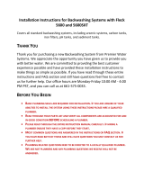
CONTROL VALVE ASSEMBLY
2510 AIO SXT
CONTROL VALVE ASSEMBLY
Item No. QTY Part No. Description
1 ................... 1 ......... 251006-007 ........... Time Clock, AIO Filter, U.S.
Transformer, Hardwater Bypass,
1” Deflector, DLFC 4.0 GPM,
Environmental Backplate
61500-2510 AIO Rev C

FLECK 2510 AIO SXT Service Manual • 9
Item No. QTY Part No. Description
1 ..............1 ...... 13030 ..............Retainer, Distributor Tube
O-Ring
2 ..............1 ...... 18303 ..............O-Ring, -336
3 ..............1 ...... 13304 ..............O-Ring, -121
4 ..............1 ...... 19197 ..............Ring, Slip, Ladder Valve
5 ..............1 ...... 19322 ..............Adapter Base, 2510
6 ..............1 ...... 19936 ..............Seal, 2510 Base
7 ..............1 ...... 19899 ..............Clamp, Female, 2510
8 ..............1 ...... 19998 ..............Pivot, Clamp, 2510
9 ..............1 ...... 19900 ..............Clamp, Male, 2510
10 ............1 ...... 60705-40 .........DLFC, Plastic 4.0 GPM
11 ............1 ...... 19328 ..............Valve Body, 2510
12 ............1 ...... 18312 ..............Retaining Clip
13 ............1 ...... 19228-01 .........Adapter Assy, Coupling,
5600
14 ............1 ...... 61662-01 .........Kit, 2510 AIO, Service
15 1 ...... 62116 ..............Air Check Assy, 2510
16 ............1 ...... 60480-000 .......Injector Assy, 1600,
#00, Plastic 2750-2900,
Complete
....... 60480-00 .........Injector Assy, 1600
#0, Plastic 2750-2900,
Complete
....... 60480-01 .........Injector Assy, 1600
#1, Plastic 2750-2900,
Complete
....... 60480-02 .........Injector Assy, 1600
#2, Plastic 2750-2900,
Complete
....... 60480-03 .........Injector Assy, 1600
#3, Plastic 2750-2900,
Complete
....... 60480-04 .........Injector Assy, 1600
#4, Plastic 2750-2900,
Complete
17 ............1 ...... 19228-02 .........Adapter Assy, Coupling,
2510AIO
Not Shown
1 ...... 11098 ..............Stuffer Tool Assy,
2510/2750
1 ...... 13061 ..............Puller Assy, Port Ring
2510/2750
1 ...... 12874 ..............Hook, Seal
1 ...... 1030043 ..........Deflector, 1”, Turbulator
CONTROL VALVE ASSEMBLY
CONTINUED

10 • FLECK 2510 AIO SXT Service Manual
8
10
11
12
6
1
15
13
16
2
25
5
7
3
4
14
26
17
18
22
21
9
28
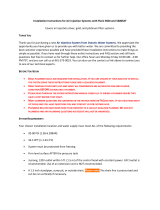
POWERHEAD
19
33
37
36
POWERHEAD ASSEMBLY
61500-2510 AIO Rev C

FLECK 2510 AIO SXT Service Manual • 11
Item No. QTY Part No. Description
1 ..............1 ...... 18697-15 .........Backplate, Hinged
2 ..............1 ...... 13881 ..............Bracket, Hinge Timer,
900SE
3 ..............1 ...... 41546 ..............Bracket, Timer, 2510SXT,
2750SXT
4 ..............1 ...... 19889 ..............Housing, Circuit Board
5 ..............4 ...... 13296 ..............Screw, Hex Wsh, 6-20 X 1/2
6 ..............2 ...... 10300 ..............Screw, Hx Wash Head, 8 x
3/8
7 ..............2 ...... 11384 ..............Screw, Phil, 6-32 x 1/4 Zinc
8 ..............1 ...... 42579 ..............Motor, Drive, 24VAC/DC,
50-60 Hz Fam 1
9 ..............2 ...... 10231 ..............Screw, Slot Hex,
1/4-20 x 1/2
10 ............1 ...... 60160-15 .........Drive Cam Assy, Stf, Blue,
2900
11 ............2 ...... 10218 ..............Switch, Micro
12 ............2 ...... 14923 ..............Screw, Pan Hd Mach,
4-40 x 1
13 ............1 ...... 27172 ..............Stand-Off, Timer,
2510SE/2750SSE
14 ............1 ...... 21363 ..............Screw, Hex Head,
M4 X 12MM
15 ............1 ...... 14265 ..............Clip, Spring
16 ............1 ...... 14202-01 .........Screw, Hex Washer,
#8-32 X 5/16
17 ............1 ...... 44098U ...........Circuit Board, SXT, Unprgm
18 ............1 ...... 42864 ..............Wire Harness, SXT
19 ............1 ...... 44144 ..............Transformer, US, 24V 40VA,
W/O
21 ............2 ...... 14044 ..............Tie, Cable, Plastic
22 ............2 ...... 40422 ..............Wire Nut, Min 2 #22 Wires
25 ............1 ...... 13547-01 .........Strain Relief, Euro Round
Cord
26 ............1 ...... 42635-01 .........Front Cover, SXT, Square,
Black
28 ............1 ...... 10338 ..............Pin, Roll, 3/32 X 7/8
33 ............1 ...... 19691 ..............Plug, .750 DIA. Hole, Flush
36 ............1 ...... 43560 ..............Fitting, Brine Valve, Steel
37 ............1 ...... 10269 ..............Nut, Jam, 3/4-16_v1
POWERHEAD ASSEMBLY
CONTINUED

2510 VALVE ACCESSORIES
Covers
60219-02 .....................Cover Assy, Environmental, Black
w/clear window
Bypasses
60041SS.......................1” Bypass, SS, NPT
60040SS.......................3/4” Bypass, SS, NPT
60049 ...........................Bypass, Plastic
Yokes
19620-01 .....................Yoke Assy, 3/4", r/angle, 90 deg.
18706 ...........................1" Yoke, Plastic NPT
18706-10 .....................1" Yoke, Plastic BSP
18706-02 .....................3/4" Yoke, Plastic NPT
18706-12 .....................3/4" Yoke, Plastic BSP
13708-40 .....................1” Yoke, Sweat
41026-01 .....................1” Yoke, SS, NPT
42690 ...........................3/4” Yoke, Sweat
41027-01 .....................3/4” Yoke, SS, NPT
Washers
19153 ...........................Washer, Flow, 0.6 GPM
19152 ...........................Washer, Flow, 0.8 GPM
12085 ...........................Washer, Flow, 1.2 GPM
19150 ...........................Washer, Flow, 1.3 GPM
12086 ...........................Washer, Flow, 1.5 GPM
12087 ...........................Washer, Flow, 2.0 GPM
12088 ...........................Washer, Flow, 2.4 GPM
12089 ...........................Washer, Flow, 3.0 GPM
12090 ...........................Washer, Flow, 3.5 GPM
12091 ...........................Washer, Flow, 4.0 GPM
19147 ...........................Washer, Flow, 4.5 GPM
12092 ...........................Washer, Flow, 5.0 GPM
17814 ...........................Washer, Flow, 6.0 GPM
12408 ...........................Washer, Flow, 7.0 GPM
17943 ...........................Washer, Flow, 8.0 GPM
17944 ...........................Washer, Flow, 9.0 GPM
16529 ...........................Washer, Flow, 10.0 GPM
16735 ...........................Washer, Flow, 12.0 GPM
16736 ...........................Washer, Flow, 15.0 GPM
Drain Elbows
19699 ...........................1/2" Drain Elbow, 45
13121 ...........................5/8" Drain Elbow, 90
Hose Barbs
13308 ...........................1/2" Straight Hose Barb
13308-01 .....................5/8" Straight Hose Barb
Collectors
18280 ...........................Top Collector, 1.050
18280-01 .....................Top Collector, 1.050 Wide
18280-02 .....................Top Collector, 1.050 Narrow
DLFC
60705-00 .....................DLFC, Plastic, Blank
60706-8.0 ....................DLFC, QC x 3/4”F, 8.0 GPM
60706-9.0 ....................DLFC, QC x 3/4”F, 9.0 GPM
60706-10 .....................DLFC, QC x 3/4”F, 10 GPM
60706-12 .....................DLFC, QC x 3/4”F, 12 GPM
60706-15 .....................DLFC, QC x 3/4”F, 15 GPM
BYPASSCOVER, ENVIRONMENTAL
WASHER
DRAIN ELBOW
COLLECTOR
YOKE
HOSE BARBS
DLFC
12 • FLECK
2510 AIO SXT Service Manual

2510 VALVE CONVERSION ASSEMBLIES
Injector Nozzles
10913-0 .......................Nozzle, Injector, #0, Red (8” Tank)
10913-00 .....................Nozzle, Injector, #00, Violet (7” Tank)
10913-000 ...................Nozzle, Injector, #000, Brown (6” Tank)
10913-1 .......................Nozzle, Injector, #1, White (9” & 10" Tank)
10913-2 .......................Nozzle, Injector, #2, Blue (12” Tank)
10913-3 .......................Nozzle, Injector, #3, Yellow (13” Tank)
10913-4 .......................Nozzle, Injector, #4, Green (14” Tank)
Injector Throats
10914-0 .......................Throat, Injector, #0, Red (8” Tank)
10914-00 .....................Throat, Injector, #00, Violet (7” Tank)
10914-000 ...................Throat, Injector, #000, Brown (6” Tank)
10914-1 .......................Throat, Injector, #1, White (9” & 10" Tank)
10914-2 .......................Throat, Injector, #2, Blue (12” Tank)
10914-3 .......................Throat, Injector, #3, Yellow (13” Tank)
10914-4 .......................Throat, Injector, #4, Green (14” Tank)
Timers
42778 ...........................Timer Assy, SXT, 2510/2750/2850
INJECTOR NOZZLE INJECTOR THROAT
TIMER ASSY, SXT
FLECK 2510 AIO SXT Service Manual • 13

14 • FLECK 2510 AIO SXT Service Manual
Item No. QTY Part No. Description
1 ..............2 ...... 13305 ..............O-ring, -119
2 ..............2 ...... 13255 ..............Clip, Mounting
3 ..............2 ...... 13314 ..............Screw, Slot Ind Hex,
8-18 x .60
4A ............ 1 ...... 18706 ..............Yoke, 1-inch , NPT, Plastic
....... 18706-02 .........Yoke, 3/4-inch , NPT,
Plastic
4B ............1 ...... 13708-40 .........Yoke, 1-inch , Sweat
....... 42690 ..............Yoke, 3/4-inch, Sweat,
Brass
....... 41027-01 .........Yoke, 3/4-inch , NPT, Cast,
Machined
....... 41026-01 .........Yoke, 1-inch , NPT, Cast,
Machined, SS
....... 18706-10 .........Yoke, 1-inch , BSP, Plastic
....... 18706-12 .........Yoke, 3/4-inch , BSP,
Plastic
....... 19620-01 .........Yoke Assy, 3/4-inch , R/
Angle, 90 Deg
5 ..............1 ...... 60049 ..............Bypass Plastic
* ..............2 ...... 19228-01 .........Adapter Assy, Coupling,
w/O-rings
*Not Shown
60049 Rev G
BYPASS VALVE ASSEMBLY (PLASTIC)
5

FLECK 2510 AIO SXT Service Manual • 15
Item No. QTY Part No. Description
1 ..............1 ...... 40614 ..............Bypass Body, 3/4-inch
....... 40634 ..............Bypass Body, 1-inch , SS
2 ..............1 ...... 14105 ..............Seal, Bypass, 560CD
3 ..............1 ...... 11972 ..............Plug, Bypass
4 ..............1 ...... 11978 ..............Side Cover
5 ..............1 ...... 13604-01 .........Label
6 ..............8 ...... 15727 ..............Screw, 10-24 x 0.5-inch
7 ..............1 ...... 11986 ..............Side Cover
8 ..............1 ...... 11979 ..............Lever, Bypass
9 ..............1 ...... 11989 ..............Screw, Hex Head,
1/4-14 x 1.5-inch
10 ............1 ...... 60040SS .......... Bypass Valve, 5600, 3/4-inch
NPT Blk Grip Lever, SS
1 ...... 60041SS .......... Bypass Valve, 5600, 1-inch
NPT Blk Grip Lever, SS
* ..............2 ...... 19228-01 .........Adapter Assy, Coupling,
w/O-rings
*Not Shown
60040SS Rev T
60041SS Rev U
BYPASS VALVE ASSEMBLY (METAL)

16 • FLECK 2510 AIO SXT Service Manual
Problem Cause Correction
Water conditioner fails to
regenerate.
Electrical service to unit has been
interrupted
Assure permanent electrical service (check fuse,
plug, pull chain, or switch)
Timer is defective. Replace timer.
Power failure. Reset time of day.
Loss of water pressure. Iron buildup in line to water conditioner. Clean line to water conditioner.
Iron buildup in water conditioner. Clean control and add mineral cleaner to mineral
bed. Increase frequency of regeneration.
Inlet of control plugged due to foreign
material broken loose from pipes by recent
work done on plumbing system.
Remove piston and clean control.
Loss of mineral through
drain line.
Air in water system. Assure that well system has proper air eliminator
control. Check for dry well condition.
Improperly sized drain line flow control. Check for proper drain rate.
Iron in conditioned water. Fouled mineral bed. Check backwash, brine draw, and brine tank fill.
Increase frequency of regeneration. Increase
backwash time. Check iron buildup on check valve
and piston.
Control cycles continuously. Misadjusted, broken, or shorted switch. Determine if switch or timer is faulty and replace
it, or replace complete power head.
Drain flows continuously. Valve is not programming correctly. Check timer program and positioning of control.
Replace power head assembly if not positioning
properly.
Foreign material in control. Remove power head assembly and inspect bore.
Remove foreign material and check control in
various regeneration positions.
Internal control leak. Replace seals and piston assembly.
TROUBLESHOOTING (2510)

FLECK 2510 AIO SXT Service Manual • 17
TROUBLESHOOTING (AIO)
Problem Cause Correction
1. Unit does not go through air draw
cycle
A. Electrical service to unit is
interrupted.
A. Inspect power supply and correct if
necessary.
B. Power failure Reset time of day
C. Timer is defective C. Verify that dial showing days moves from
day today. If it does not move, replace timer.
2. Unit does not draw air A. Drain line is kinked A. Straighten drain line
B. Water pressure to unit too low B. Pressure must be above 20 psi at all times.
Increase pressure if necessary.
C. Drain line flow control blocked C. Inspect DLFC and clean if necessary.
D. Injectors or screen plugged D. Inspect and clean or replace as necessary.
E. Internal leak in control E. Inspect piston and seals/spacers. Replace
as needed.
3. Water flows continuously to drain A. Timer motor stopped or jammed A. Replace if necessary.
B. Foreign material jammed inside
control
B. Remove piston and check.
C. Internal leak C. Inspect piston and seals/spacers. Replace
as needed.
4. Water is clear from tap, turns red
upon standing
A. Insufficient air drawn by valve A. Check valve at air draw time
B. Bypass open or leaking B. Close bypass valve and/or repair as
necessary
C. Filter bed backwashed at improper
frequency
C. Increase backwash frequency.
5. Water is red when drawn from
tap
A. Filter bed overloaded with
precipitated iron due to insufficient
backwash flow rate.
A. Inspect drain line for kinks or obstructions.
Verify drain line flow control is correct size
for application. If, after correction, manual
backwash does not clear bed of iron, filter bed
may need chemical washing.
B. Filter bed backwashed at improper
frequency
B. Increase backwash frequency.
6. Excessive pressure loss through
filter
A. Filter bed overloaded with
precipitated iron.
A. Inspect drain line for kinks or obstructions.
Verify drain line flow control is correct size
for application. If, after correction, manual
backwash does not clear bed of iron, filter bed
may need chemical washing.
B. Control in/outlet valves not fully
open.
B. Open valves
C. Sand, silt, or mud collecting in filter
media
C. Inspect well for these conditions.
D. Filter bed not properly “classified” D. Manually backwash to reclassify.
E. “Cementing” or “channelling” of
filter media.
E. Stir filter bed to break up hardened layer.
Increase backwash frequency to prevent
recurrence.
7. Milky or bubbly water. A. Excess gasses in water. A. System may require cleaning. Some
installations will naturally produce aerated
water.
8. Control cycles continuously. A. Misadjusted, broken, or shorted
switch.
A. Determine if switch or timer is faulty and
replace it, or replace complete power head.
9. Drain flows continuously. A. Valve is not programming correctly. A. Check timer program and positioning of
control. Replace power head assembly if not
positioning properly.
B. Foreign material in control. B. Remove power head assembly and inspect
bore. Remove foreign material and check
control in various regeneration positions.
C. Internal control leak. C. Replace seals and piston assembly.

18 • FLECK 2510 AIO SXT Service Manual
FLOW DATA & INJECTOR DRAW RATES

FLECK 2510 AIO SXT Service Manual • 19
SXT WIRING DIAGRAM
P1 P2
METER POWER HARNESS
44098U REV D

For Fleck
§
Product Warranties visit:
Fleck para las garantías de los productos visite:
Pour Fleck garanties produit visitez le site :
waterpurification.pentair.com
}
44425 REV A JL18
13845 BISHOPS DR., SUITE 200, BROOKFIELD, WI 53005
WATERPURIFICATION.PENTAIR.COM | CUSTOMER CARE: 800.279.9404 | tech-support@pentair.com
© 2018 Pentair Residential Filtration, LLC. All rights reserved.
§For a detailed list of where Pentair trademarks are registered, please visit waterpurification.pentair.com/brands. Pentair trademarks and logos are owned by
Pentair plc or its affiliates. Third party registered and unregistered trademarks and logos are the property of their respective owners.
13845 BISHOPS DR., SUITE 200, BROOKFIELD, WI 53005
WATERPURIFICATION.PENTAIR.COM | CUSTOMER CARE: 800.279.9404 | tech-support@pentair.com
© 2018 Pentair Residential Filtration, LLC. All rights reserved.
§For a detailed list of where Pentair trademarks are registered, please visit waterpurification.pentair.com/brands. Pentair trademarks and
logos are owned by Pentair plc or its affiliates. Third party registered and unregistered trademarks and logos are the property of their
respective owners.
PENTAIR RESIDENTIAL FILTRATION, LLC
13845 BISHOPS DR., SUITE 200 BROOKFIELD, WI 53005
262.238.4400, waterpurification.pentair.com
CUSTOMER CARE: 800.279.9404
EMAIL: techsupport@pentair.com
13845 BISHOPS DR., SUITE 200, BROOKFIELD, WI 53005
WATERPURIFICATION.PENTAIR.COM | CUSTOMER CARE:
800.279.9404 | tech-support@pentair.com
© 2018 Pentair Residential Filtration, LLC. All rights reserved.
13845 BISHOPS DR., SUITE 200, BROOKFIELD, WI 53005
P: 262.238.4400 | F: 262.238.4418
WATERPURIFICATION.PENTAIR.COM
CUSTOMER CARE: 800.279.9404
tech-support@pentair.com
© 2017 Pentair Residential Filtration, LLC
All rights reserved.
13845 BISHOPS DR., SUITE 200, BROOKFIELD, WI 53005 USA
P: 262.238.4400 | WATERPURIFICATION.PENTAIR.COM | CUSTOMER CARE: 800.279.9404 | tech-support@pentair.com
© 2018 Pentair Residential Filtration, LLC. All rights reserved.
§For a detailed list of where Pentair trademarks are registered, please visit waterpurification.pentair.com/brands. Pentair trademarks and logos are owned by
Pentair plc or its affiliates. Third party registered and unregistered trademarks and logos are the property of their respective owners.
13845 BISHOPS DR., SUITE 200, BROOKFIELD, WI 53005 USA
P: 262.238.4400 | WATERPURIFICATION.PENTAIR.COM
CUSTOMER CARE: 800.279.9404 | tech-support@pentair.com
© 2018 Pentair Residential Filtration, LLC. All rights reserved.
§
For a detailed list of where Pentair trademarks are registered,
please visit waterpurification.pentair.com/brands. Pentair
trademarks and logos are owned by Pentair plc or its affiliates.
Third party registered and unregistered trademarks and logos
are the property of their respective owners.
13845 BISHOPS DR., SUITE 200, BROOKFIELD, WI 53005 USA
P: 262.238.4400 | WATERPURIFICATION.PENTAIR.COM
CUSTOMER CARE: 800.279.9404 | tech-support@pentair.com
© 2018 Pentair Residential Filtration, LLC. All rights reserved.
§
For a detailed list of where Pentair trademarks are registered, please visit waterpurification.pentair.com/brands.
Pentair trademarks and logos are owned by Pentair plc or its affiliates. Third party registered and unregistered
trademarks and logos are the property of their respective owners.
13845 BISHOPS DR., SUITE 200, BROOKFIELD, WI 53005 USA
P: 262.238.4400 | WATERPURIFICATION.PENTAIR.COM | CUSTOMER CARE: 800.279.9404 | tech-supportpentair.com
© 2017 Pentair Residential Filtration, LLC. All rights reserved.
§For a detailed list of where Pentair trademarks are registered, please visit waterpurification.pentair.com/brands. Pentair trademarks and logos are owned by
Pentair plc or its affiliates. Third party registered and unregistered trademarks and logos are the property of their respective owners.
/