Vulcan Hart C24EA SERIES User manual

Category
Small kitchen appliances
Type
User manual
A product of VULCAN-HART LOUISVILLE, KY 40201-0696
F25213 (May 2006)
- NOTICE -
This Manual is prepared for the use of trained Vulcan Service
Technicians and should not be used by those not properly
qualified. If you have attended a Vulcan Service School for this
product, you may be qualified to perform all the procedures
described in this manual.
This manual is not intended to be all encompassing. If you have
not attended a Vulcan Service School for this product, you should
read, in its entirety, the repair procedure you wish to perform to
determine if you have the necessary tools, instruments and skills
required to perform the procedure. Procedures for which you do
not have the necessary tools, instruments and skills should be
performed by a trained Vulcan Service Technician.
Reproduction or other use of this Manual, without the express
written consent of Vulcan, is prohibited.
C24EA3 BASIC SHOWN
SERVICE MANUAL
C24EA SERIES
ATMOSPHERIC
STEAMERS
C24EA3 208/240V PRO
C24EA3 480V PRO
C24EA5 208/240V PRO
C24EA5 480V PRO
C24EA3 208/240V BASIC
C24EA3 480V BASIC
C24EA5 208/240V BASIC
C24EA5 480V BASIC
ML-136037
ML-136044
ML-136038
ML-136047
ML-136043
ML-136045
ML-136046
ML-136048
For additional information on Vulcan-Hart Company or to locate an authorized
parts and service provider in your area, visit our website at www.vulcanhart.com
MODEL C24EA - GENERAL
F25213 (May 2006) Page 2 of 52
TABLE OF CONTENTS
GENERAL ................................................................................ 3
COVERS AND PANELS ..................................................................... 6
DOOR.................................................................................... 8
DRAIN .................................................................................. 12
COOKING COMPARTMENT ................................................................. 13
THERMOSTATS .......................................................................... 15
Hold Thermostat ....................................................................... 15
High-Limit Thermostat .................................................................. 15
Condensate Thermostat ................................................................. 16
TIMER .................................................................................. 17
HEATING ELEMENT ....................................................................... 18
SUPER HEATER .......................................................................... 20
WATER LEVEL CONTROL COMPONENTS ..................................................... 22
Water Level Controls ................................................................... 22
Water Level Control Board ............................................................... 23
Water Level Probes .................................................................... 23
Filtered and Non-Filtered Water Solenoid Valves ............................................. 24
Manual Drain Valve (Basic) .............................................................. 25
Motorized Drain Valve (Professional) ....................................................... 26
SWITCHES, BUZZER AND SOLENOIDS ....................................................... 28
On/Off Switch ......................................................................... 28
Door Switch .......................................................................... 29
Pressure Switch ....................................................................... 30
Vacuum Relief Solenoid ................................................................. 32
Buzzer .............................................................................. 33
STEAM GENERATOR TANK................................................................. 34
ELECTRICAL OPERATION .................................................................. 36
Component Function ................................................................... 36
Component Location ................................................................... 38
Sequence of Operation .................................................................. 42
Wiring Diagrams ....................................................................... 45
TROUBLESHOOTING ...................................................................... 50
CONDENSED SPARE PARTS LIST ........................................................... 52
©VULCAN 2006
MODEL C24EA - GENERAL
F25213 (May 2006)Page 3 of 52
GENERAL
INTRODUCTION
This manual is applicable to the models and ML numbers listed on the cover page. Procedures apply to all models
unless specified otherwise.
Steam Cooking
Atmospheric steamers offer an efficient way to produce many foods in either small portions or larger batches.
Atmospheric convection steam cooking will steam cook fresh foods or will steam defrost and cook frozen foods
providing the maximum color, flavor and nutritional value with the least expenditure of energy and labor. The
atmospheric steaming compartment allows the operator to open and close the door anytime during a cooking
cycle. The generator element will shut off when the door is opened then re-start when the door is closed.
MODELS COVERED
Model Designations (based on 2.5 inch pan depth)
C24EA3 Three pan - Basic or Professional
C24EA5 Five pan - Basic or Professional
MODEL C24EA - GENERAL
F25213 (May 2006) Page 4 of 52
SPECIFICATIONS
NOTE: All C24EA steamers, with exception of 480V steamers, are shipped pre-wired for 208/60/3 operation.
Steamer heating element wiring connection change is required if connecting to 208/60/1, 240/60/1 or 240/60/3
electrical service.
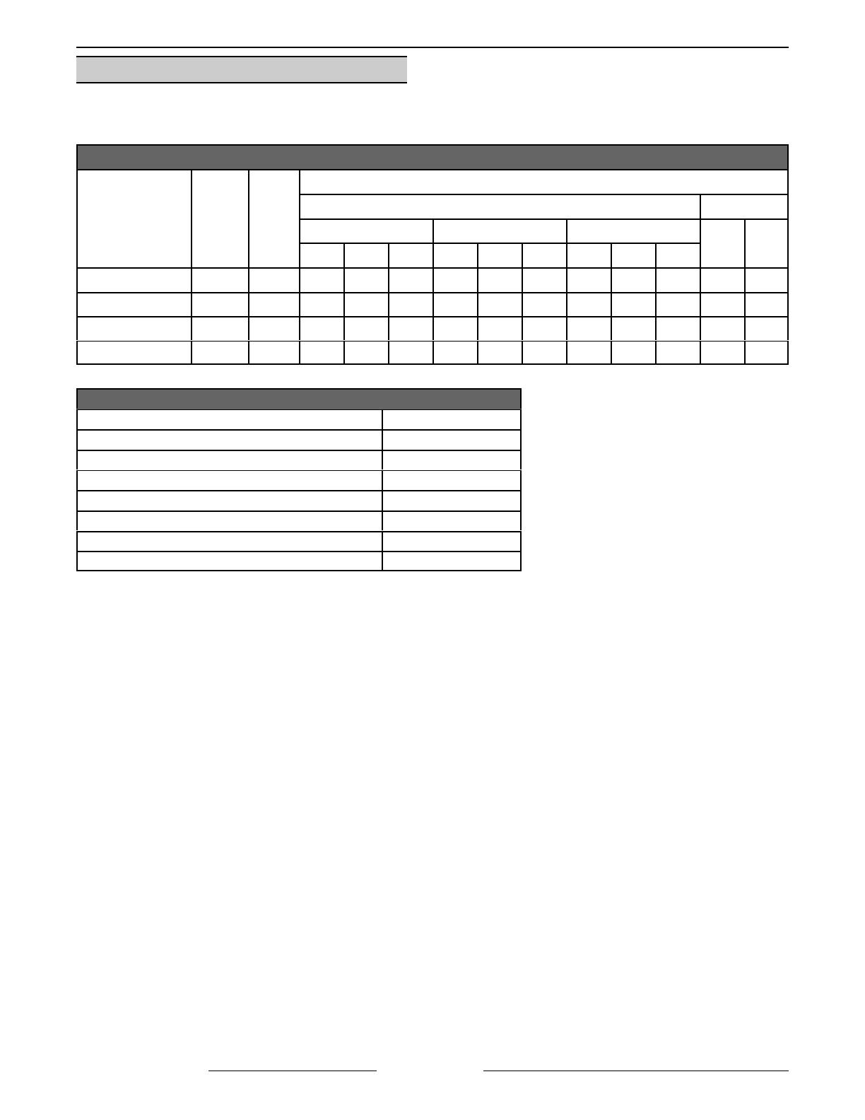
ELECTRICAL SPECIFICATIONS
MODEL
TOTAL
kW
Hz.
AMPERAGE
3 PHASE 1 PHASE
208V 240V 480V
208V 240V
L1 L2 L3 L1 L2 L3 L1 L2 L3
C24EA3 - Basic 8.5 50/60 26.5 26.5 17.7 20.5 20.5 20.5 10.3 10.3 10.3 40.9 35.4
C24EA5 - Basic 15.0 50/60 46.8 46.8 31.2 36.1 36.1 36.1 18.0 18.0 18.0 72.1 62.5
C24EA3 - Pro 9.25 50/60 26.5 28.9 20.0 20.5 23.2 23.2 10.2 11.6 11.6 43.6 38.5
C24EA5 - Pro 15.75 50/60 46.8 49.2 33.6 36.1 38.8 38.8 18.0 19.4 19.4 74.8 65.6
WATER SUPPLY REQUIREMENTS
! Supply pressure should be ........................ 20-60 psig
! In line strainer for supply line (Supplied)
! Total dissolved solids (TDS)* .................... less than 60 ppm
! Total alkalinity ........................................... less than 20 ppm
! Silica ......................................................... less than 13 ppm
! Chloride .................................................... less than 4.0 ppm
! PH factor ................................................... 6.5 to 8
! Undissolved Solids..................................... less than 5 microns
*17.1 ppm = 1 grain of hardness
Water hardness below 4 grains/gal requires water treatment to reduce
potential corrosion. Hardness above 6 grains/gal should be treated by
water conditioner, water softener or in-line treatment.
Water Conditioning
It is recommended that a local water treatment specialist be consulted before the installation of any steam
generating equipment.
Furnishing the steam generator with properly conditioned water to reduce scale formation is important. Scale
formation will reduce steam output, cause premature component failure and shorten equipment life. Most water
supplies contain scale producing minerals such as calcium and magnesium. As steam is generated, the minerals
remain and dissolve into the remaining water. As the concentration of these minerals increases past a certain
point, they precipitate from the water and coat the inside of the tank, heating elements, thermostat bulbs and water
level probes. Because of the high temperature of these surfaces, the precipitated minerals bake onto them and
become very difficult to remove.
This phenomenon causes several problems:
1. Reduces the heat transfer efficiency of the heaters.
2. Causes premature failure of the heaters.
3. Water level probes will give false readings.
4. Thermostat bulbs will sense temperature incorrectly.
These problems are common to any manufacturer's steamer regardless of design, but they can all be prevented
by furnishing the steam generator tank with properly conditioned water. Vulcan recommends the water contain
less than 60ppm of total dissolved solids (TDS) and have a PH factor between 6.5 to 8.
MODEL C24EA - GENERAL
F25213 (May 2006)Page 5 of 52
Other chemical properties in water supplies can also affect good steam generation and vary from within each state
and locality.
The water level probes in the steam generator tank use ions in the water to detect the water level. Do not use fully
demineralized or de-ionized water since it is non-conductive and the water level can not be detected.
NOTE: The use of strainers, or filters will not remove minerals from the water.
Steamers that operate over a long period of time without the benefit of properly conditioned water, which have
developed a heavy scale build up, should be cleaned before connecting to a conditioned water supply.
REFERENCE MATERIAL
For replacement parts, refer to Catalog of
Replacement Parts F-43123.
For operation, care and cleaning instructions, refer to
Installation and Operation Manual F-35428.
LUBRICATION
Component Lubrication Type
Heating Element
Screws
Never Seez
All NPT Fittings Pipe Thread Sealant, Loctite
565
Door Handle
Sliding Bracket
Lubriplate 630AA
TOOLS
Standard set of hand tools.
VOM with A/C current tester (any quality VOM
with a sensitivity of at least 20K ohms per volt
can be used).
Anti Static Kit, part no. TL - 84919.
Special
Torque Wrench - Capable of measuring
70 in*lb.
Aluminum Foil Tape - (McMaster-Carr Part No.
7631A21) or equivalent.
Pressure Gauge Assembly
Low Pressure Gauge - 0 to 5 psi.
recommended (Grainger Part No. 2C641).
Water Hose Coupling - swivel type
(Grainger Part No. 4KG87).
Reducer Bushing (Grainger Part No.
6MN61).
Pipe thread sealant (as required).
MODEL C24EA - COVERS AND PANELS
F25213 (May 2006) Page 6 of 52
RIGHT SIDE SHOWN
COVERS AND PANELS
WARNING: DISCONNECT THE ELECTRICAL POWER TO THE MACHINE AND FOLLOW
LOCKOUT / TAGOUT PROCEDURES.
RIGHT AND LEFT SIDE PANELS
NOTE: Removal of left side panel is identical to the
procedure for the right side panel.
1. Remove screws from the bottom of panel being
removed.
2. Pull bottom of panel out and slide down to clear
top cover.
3. Reverse procedure to install.
TOP COVER
1. Remove RIGHT AND LEFT SIDE PANELS.
2. Remove the screws securing top cover to rear
panel.
3. Remove the screws securing top cover to front
panel. Screws are located on either side of the
cooking cavity.
4. Disconnect the delime hose from delime port
fitting.
5. Lift top cover off machine.
6. Reassemble parts removed in reverse order.
7. Check machine for proper operation.
MODEL C24EA - COVERS AND PANELS
F25213 (May 2006)Page 7 of 52
SCREW LOCATION
REAR PANEL
WARNING: DISCONNECT THE
ELECTRICAL POWER TO THE
MACHINE AND FOLLOW LOCKOUT /
TAGOUT PROCEDURES.
1. Remove screws securing top cover to rear
panel and rear panel to steamer frame.
NOTE: If incoming plumbing or drain interferes with
rear panel removal, turn off water supply and
disconnect plumbing to machine.
2. Remove LEFT SIDE PANEL.
3. Disconnect vacuum relief hose from fitting.
4. Pull bottom of rear panel away from machine
and plumbing.
5. Reassemble parts removed in reverse order.
TOP COVER REMOVED FOR CLARITY
MODEL C24EA - DOOR
F25213 (May 2006) Page 8 of 52
DOOR
WARNING: DISCONNECT THE ELECTRICAL POWER TO THE MACHINE AND FOLLOW
LOCKOUT / TAGOUT PROCEDURES.
REMOVAL
1. Close door.
2. Remove LEFT SIDE PANEL as outlined in
COVERS AND PANELS.
3. Remove nuts from upper hinge located inside
front panel.
4. Open door slightly, and while holding door, pull
upper hinge away from front panel.
5. Pull upper hinge out of upper door hinge
bushing.
6. Lift door assembly up and off lower door hinge.
7. Reinstall parts removed in reverse order of
removal.
8. Check door for fit and proper sealing of gasket.
GASKET
1. Open door.
2. Remove the shoulder screws and pan pusher
bracket from gasket plate.
3. Remove gasket plate.
4. Remove gasket from inner door panel.
5. Remove RTV from bottom part of inner door
panel. Apply new RTV 109 to bottom of door
where shown when assembling gasket to door.
6. Place a small amount of RTV109 into the inner
door panel gasket screw holes before
assembly.
7. Position the new gasket on gasket plate and
reverse procedure to install.
MODEL C24EA - DOOR
F25213 (May 2006)Page 9 of 52
DOOR HANDLE
Removal
1. Open door.
2. Remove screws from top and bottom of door
assembly.
3. Pull outer door housing away from inner door
panel starting at the hinge side of door to
separate the door halves.
NOTE: The smaller radius of the step spacers fit into
the slots of the outer door housing and is used to
provide clearance for handle operation.
4. Remove lock nuts and stepped spacers from
threaded studs of door handle.
Installation
1. Apply Lubriplate 630AA around slots of outer
door housing where step spacers contact
housing.
2. Install door handle into outer door housing such
that hinge side of door housing is to the left and
arrow on handle is pointed upward.
3. Install step spacer with smaller radius toward
handle and door housing. Smaller radius is a
slip fit with outer door housing slot.
4. Install lock nuts and tighten until no gap exists
between handle, step spacer and lock nut. Do
not over-tighten lock nuts.
5. Close inner door panel so that latch mechanism
engages striker on front panel.
6. Install outer door housing onto inner door panel.
7. Align the top and bottom screw holes of outer
door housing with inner door panel.
8. Apply Loctite 242 to threads of screws before
assembling.
9. Install screws to secure door halves together.
10. Check opening and closing operation of door.
MODEL C24EA - DOOR
F25213 (May 2006) Page 10 of 52
LATCH ASSEMBLY
Removal and Disassembly
1. Separate outer door housing assembly from
inner door panel as outlined under DOOR
HANDLE.
2. Remove screws securing latch assembly to
inner door panel and remove latch mechanism.
3. Remove E-clip from latch assembly pins and
pull pins from latch mechanism.
4. Remove retaining pin from spring pin.
5. Separate sliding bracket from stationary
bracket.
Assembly
1. Apply Lubriplate 630AA to sides of sliding
bracket.
2. Insert spring pin into bottom of sliding bracket.
A. Place spring over spring pin.
3. Assemble sliding bracket into stationary
bracket.
4. While holding head of spring pin against bottom
of sliding bracket, insert spring pin into keeper
hole in bottom of stationary bracket.
A. Secure spring pin in place with retaining
pin.
NOTE: Install pins such that heads of pins will be
facing inward toward hinge side of inner door panel
when latch assembly is installed.
5. Install pins to assemble stationary and sliding
brackets together.
A. Secure pins into position with E-clip.
Installation
1. Install latch assembly onto inner door panel with
spring pin toward bottom of door panel.
A. Apply Loctite 271 to threads of screws
before assembly and secure latch
assembly to inner door panel.
MODEL C24EA - DOOR
F25213 (May 2006)Page 11 of 52
2. Install outer door housing assembly as outlined
in DOOR HANDLE.
3. Check opening and closing operation of door.
4. Check steamer for proper operation and leaks
around door seal.
HINGE BEARINGS
1. Close door.
2. Remove LEFT SIDE PANEL as outlined in
COVERS AND PANELS.
3. Remove nuts from upper hinge located inside
front panel.
4. Open door slightly, and while holding door, pull
upper hinge away from front panel.
5. Pull upper hinge out of upper door hinge
bearing.
6. Lift door assembly up and off lower door hinge.
7. Pry hinge bearing out from door assembly.
8. Remove outer door housing.
CAUTION: Do not drive bearing into place. The
inner door panel could be damaged. Press
bearing into position.
NOTE: When replacing door hinge bearings, replace
both hinge bearings.
9. Position replacement hinge bearing over hinge
opening in door assembly.
A. Press hinge bearing fully into door
assembly using a C-clamp or equivalent.
10. Reassemble parts removed in reverse order.
11. Check door for fit and proper door gasket
sealing.
DOOR LATCH ADJUSTMENT
Opening a Jammed Door
CAUTION: Should the steamer door jam and
cannot be opened, DO NOT FORCE OR PRY
the
door as damage will occur.
1. Lift up on bottom of door at the handle end to
disengage latch.
A. If door does not open, remove the right
side panel as outlined in RIGHT AND
LEFT SIDE PANELS.
B. Locate the striker that catches on door
latch near steam chamber on front panel.
C. Remove the nut from striker and this
should release it from the panel.
D. Open door.
2. Remove striker.
3. Remove any burrs on striker that may cause
latch to stick.
4. Apply Loctite 271 to threads of striker.
5. Reinstall striker with slotted side up. Snug
striker nut. Perform Adjustment, so door will not
jam.
MODEL C24EA - DRAIN BOX
F25213 (May 2006) Page 12 of 52
CLOSE-UP FROM RIGHT SIDE OF STEAMER
Adjustment
1. Reinstall striker with slot pointing upward and
hand tighten nut only.
2. Close door to center striker in front panel
mounting hole.
3. Open door and check striker slot for horizontal
alignment. The slot on striker must be kept
horizontal in order for door latch to catch
properly and latch.
4. Once proper slot alignment has been set, hold
striker close to its base then tighten the striker
nut. Be careful not to damage striker slot when
tightening or door may not latch properly.
NOTE: Do not over-tighten nut. If over-tightened,
striker may turn and change alignment.
NOTE: If door does not open easily, add shims
between striker and cabinet front. When adding
shims make certain that door gasket seals properly
and steamer does not leak. Remove shims as
necessary until leaking stops.
DRAIN BOX
WARNING: DISCONNECT THE ELECTRICAL POWER TO THE MACHINE AND FOLLOW
LOCKOUT / TAGOUT PROCEDURES.
REMOVAL AND REPLACEMENT
1. Turn off machine to drain steam generator tank.
Allow steamer to complete drain cycle.
A. Turn off water supply.
2. Disconnect the drain plumbing from drain box
outlet fitting.
3. Remove the RIGHT AND LEFT SIDE PANELS
as outlined in COVERS AND PANELS.
NOTE: Use plumbing sealant when reinstalling
condensate thermostat.
4. Disconnect the condensate thermostat electrical
wiring.
A. Remove the condensate thermostat from
drain box.
5. Disconnect the cooling solenoid and cooking
compartment drain hoses.
NOTE: The steam generator drain hose is accessed
from right side of machine.
6. Disconnect the steam generator drain hose.
7. Remove the nuts securing drain box to back
plate at rear of steamer.
8. Remove drain box from steamer.
9. Reassemble parts removed in reverse order.
10. Check steamer for proper operation and leaks
around condensate thermostat and hose
connection points.
MODEL C24EA - COOKING COMPARTMENT
F25213 (May 2006)Page 13 of 52
PROFESSIONAL MODEL SHOWN
COOKING COMPARTMENT
WARNING: DISCONNECT THE ELECTRICAL POWER TO THE MACHINE AND FOLLOW
LOCKOUT / TAGOUT PROCEDURES.
REMOVAL AND REPLACEMENT
NOTE: The cooking compartment and front panel
are constructed as an assembly and cannot be
separated.
1. Turn off machine to drain steam generator tank.
Allow steamer to complete drain cycle.
A. Turn off water supply.
2. Remove the RIGHT AND LEFT SIDE PANELS
and TOP COVER as outlined in COVERS AND
PANELS.
3. Remove the DOOR as outlined in HINGE
BUSHING.
A. Remove both hinges.
4. Remove the timer, indicator light, on/off switch
(Professional models only), striker and door
switch assembly.
5. Remove the vacuum breaker and hose as an
assembly.
6. Disconnect steam inlet hose from the steam
inlet port.
A. Remove the steam inlet port.
7. Disconnect the drain hose from rear of cooking
compartment.
NOTE: Screws are located on either side of cooking
compartment securing front panel to lower louvered
panel.
MODEL C24EA - COOKING COMPARTMENT
F25213 (May 2006) Page 14 of 52
8. Remove the screws securing front panel to
lower louvered panel.
9. Remove the nuts securing rear of cooking
compartment to the vertical mounting brackets
(four places - located between cooking
compartment and steam generator).
10. Remove cooking compartment assembly.
11. If removed or replacing cooking compartment,
install insulation around cooking compartment.
Secure insulation into position using high
temperature aluminum foil tape.
12. Reinstall parts removed in reverse order.
13. Check DOOR LATCH ADJUSTMENT.
MODEL C24EA - THERMOSTATS
F25213 (May 2006)Page 15 of 52
THERMOSTATS
HOLD THERMOSTAT
WARNING: DISCONNECT THE
ELECTRICAL POWER TO THE
MACHINE AND FOLLOW LOCKOUT /
TAGOUT PROCEDURES.
1. Turn off machine to drain steam generator tank.
Allow steamer to complete drain cycle.
A. Turn off water supply.
2. Remove RIGHT SIDE PANEL as outlined under
COVERS AND PANELS.
3. Disconnect electrical lead wires from hold
thermostat.
4. Remove hold thermostat from steam generator
tank.
NOTE: Apply Loctite 565 to threads of hold
thermostat before assembly.
5. Reassemble parts removed in reverse order of
removal.
6. Check steamer for proper operation and leaks
around hold thermostat.
HIGH-LIMIT THERMOSTAT
WARNING: DISCONNECT THE
ELECTRICAL POWER TO THE
MACHINE AND FOLLOW LOCKOUT /
TAGOUT PROCEDURES.
Removal
1. Turn off machine to drain steam generator tank.
Allow steamer to complete drain cycle.
A. Turn off water supply.
2. Remove RIGHT SIDE PANEL and TOP
COVER as outlined under COVERS AND
PANELS.
3. Remove HEATING ELEMENT.
4. Loosen hose clamp securing capillary bulb to
top of heating element.
5. Fully loosen the small capillary tube
compression nut and slide it away from heating
element.
6. Remove large capillary nut from heater base
plate and slide it away from heating element.
7. Remove capillary tube from heating element.
8. Disconnect electrical wiring to high-limit
thermostat.
9. Remove high-limit thermostat from mounting
bracket.
MODEL C24EA - THERMOSTATS
F25213 (May 2006) Page 16 of 52
Installation
1. Insert capillary bulb through large compression
nut.
A. Route capillary bulb through top of heating
element.
B. Position capillary bulb between top of
second and third heating element coils.
Secure with hose clamp to second coil as
shown.
2. Apply pipe thread sealant to threads of large
capillary nut then install large compression nut.
A. Pull excess capillary tubing out of heating
element through large nut. Route capillary
tubing such that there are no sharp bends.
B. Tighten the small capillary compression nut
into the large compression nut.
NOTE: Install a new gasket when reassembling
steam generator tank. Temporarily secure gasket in
place with RTV109.
3. Reinstall remaining parts removed in reverse
order.
4. Torque heating element screws to 70 in*lb
following the heating element tightening
sequence as found under HEATING ELEMENT.
5. Check steamer for proper operation and leaks
around heating element gasket and high-limit
thermostat.
CONDENSATE THERMOSTAT
WARNING: DISCONNECT THE
ELECTRICAL POWER TO THE
MACHINE AND FOLLOW LOCKOUT /
TAGOUT PROCEDURES.
1. Turn off machine to drain steam generator tank.
Allow steamer to complete drain cycle.
A. Turn off water supply.
2. Remove LEFT SIDE PANEL as outlined in
COVERS AND PANELS.
3. Disconnect electrical wiring to condensate
thermostat.
4. Remove condensate thermostat from drain box.
5. Reassemble parts removed in reverse order of
removal. Make certain to apply Loctite 565
thread sealant to threads of thermostat before
assembly.
6. Check steamer for proper operation and leaks
around condensate thermostat.
MODEL C24EA - TIMER
F25213 (May 2006)Page 17 of 52
TIMER
WARNING: DISCONNECT THE ELECTRICAL POWER TO THE MACHINE AND FOLLOW
LOCKOUT / TAGOUT PROCEDURES.
REMOVAL AND REPLACEMENT
NOTE: The basic and professional model steamers
use the same 60 minute timer. When the timer
reaches zero, an external buzzer will sound and
steam will stop entering the cooking compartment.
The Professional steamer has extra components to
utilize the constant steam setting allowing the
steamer to operate continuously.
1. Remove RIGHT SIDE PANEL as outlined under
COVERS AND PANELS.
2. Note electrical connections then disconnect
wiring to timer.
3. Pull knob from timer shaft.
A. Remove rotary shaft seal from timer shaft
then remove timer from front panel.
B. Inspect rotary shaft seal. Replace if
damaged, worn or signs of moisture
migration into control area around timer
shaft is evident.
4. Reverse procedure to install.
5. Check steamer for proper operation.
PROFESSIONAL MODEL SHOWN
MODEL C24EA - HEATING ELEMENT
F25213 (May 2006) Page 18 of 52
BASIC MODEL SHOWN
HEATING ELEMENT
WARNING: DISCONNECT THE ELECTRICAL POWER TO THE MACHINE AND FOLLOW
LOCKOUT / TAGOUT PROCEDURES.
REMOVAL AND REPLACEMENT
1. Turn off machine to drain steam generator tank.
Allow steamer to complete drain cycle.
A. Turn off water supply.
2. Remove RIGHT SIDE PANEL and TOP
COVER as outlined under COVERS AND
PANELS.
3. Note heating element wire connection points
then disconnect heating element lead wires
from contactors.
4. Carefully position high-limit thermostat capillary
tube to facilitate heating element removal.
Avoid creating sharp bends or kinks in the
capillary tube.
5. Remove screws and lock washers securing
heating element to tank.
6. Pull heating element out of steam generator
tank.
7. Note mounting position of high-limit thermostat
bulb then remove bulb from heating element.
A. Remove high-limit capillary tube
compression fitting and remove high-limit
capillary and bulb from heating element.
NOTE: Install a new gasket when reassembling
steam generator tank. Temporarily secure gasket in
place with RTV109.
8. Remove gasket from steam generator tank.
A. Clean remaining sealant from top lip of
steam generator tank.
NOTE: Refer to HIGH-LIMIT THERMOSTAT for
proper placement of capillary bulb.
MODEL C24EA - HEATING ELEMENT
F25213 (May 2006)Page 19 of 52
9. Reassemble parts removed in reverse order of removal. Tighten heating element screws evenly to 70 in*lbs.
Follow tightening sequence pattern as shown in illustration.
10. Check steamer for proper operation and leaks around heating element.
DIAGNOSTIC CHECKS
WARNING: CERTAIN PROCEDURES IN THIS SECTION REQUIRE ELECTRICAL TEST OR MEASUREMENTS
WHILE POWER IS APPLIED TO THE MACHINE. EXERCISE EXTREME CAUTION AT ALL TIMES. IF TEST
POINTS ARE NOT EASILY ACCESSIBLE, DISCONNECT POWER AND FOLLOW LOCKOUT / TAGOUT
PROCEDURES, ATTACH TEST EQUIPMENT AND REAPPLY POWER TO TEST.
1. Check voltage across heating element wires at limiting and regulating contactor terminals.
A. If voltage is correct, check current draw (step 2).
B. If voltage is not correct, check the following:
1) Voltage supply to steamer.
2) Fuses or breaker blown.
3) Power to contactor coils.
4) Contactors not pulling in. (Mechanical)
2. Check current draw (amps) through heating element lead wires using an amp clamp meter.
A. If current is correct, then heating element is ok.
B. If current is not correct, check element resistance (step 3).
3. Remove one lead wire of each heating element from the regulating contactor and check the individual
element resistance using a VOM.
A. If resistance readings are not correct, replace heating element.
MODEL VOLTAGE TOTAL kW
CURRENT PER
ELEMENT
RESISTANCE PER ELEMENT
(OHMS)
3 Pan
208
1
8.5 10.2 20.4
240
2
8.5 11.8 20.4
480Y/277
3
8.5 10.2 27.1
5 Pan
208 15 18.0 11.5
240 15 20.8 11.5
480Y/277
3
15 18.1 15.3
1
Four elements used.
2
Three elements used.
3
Elements of 480V machines are connected in Wye configuration for 277V across each element.
NOTE: Values in table are nominal. Tolerance is ±10 %.
4. Check steamer for proper operation.
OVERHEAD VIEW OF HEATING ELEMENT
MODEL C24EA - SUPER HEATER
F25213 (May 2006) Page 20 of 52
SUPER HEATER
WARNING: DISCONNECT THE ELECTRICAL POWER TO THE MACHINE AND FOLLOW
LOCKOUT / TAGOUT PROCEDURES.
REMOVAL AND REPLACEMENT
1. Turn off machine to drain steam generator tank.
Allow steamer to complete drain cycle.
A. Turn off water supply.
2. Remove RIGHT SIDE PANEL as outlined under
COVERS AND PANELS.
3. Note super heater wiring connection points then
disconnect heating element lead wires from the
relay (K4) and the regulating contactor.
4. Peel back insulation from head of heater
element.
5. Remove super heater element from insulated
piping assembly.
NOTE: Top cover removed for clarity. Removal of
top cover is not necessary to service super heater.
6. Reassemble parts removed in reverse order of
removal.
A. Apply pipe thread sealant to threads of
super heater element before assembly.
B. Tape insulation around head of heater
element using high-temperature aluminum
foil tape.
7. Check to make sure insulated piping assembly
is horizontal or element head end of assembly
is slightly elevated.
8. Check steamer for proper operation and leaks
around super heater.
9. Reinstall panels and top cover.
  • Page 1 1
  • Page 2 2
  • Page 3 3
  • Page 4 4
  • Page 5 5
  • Page 6 6
  • Page 7 7
  • Page 8 8
  • Page 9 9
  • Page 10 10
  • Page 11 11
  • Page 12 12
  • Page 13 13
  • Page 14 14
  • Page 15 15
  • Page 16 16
  • Page 17 17
  • Page 18 18
  • Page 19 19
  • Page 20 20
  • Page 21 21
  • Page 22 22
  • Page 23 23
  • Page 24 24
  • Page 25 25
  • Page 26 26
  • Page 27 27
  • Page 28 28
  • Page 29 29
  • Page 30 30
  • Page 31 31
  • Page 32 32
  • Page 33 33
  • Page 34 34
  • Page 35 35
  • Page 36 36
  • Page 37 37
  • Page 38 38
  • Page 39 39
  • Page 40 40
  • Page 41 41
  • Page 42 42
  • Page 43 43
  • Page 44 44
  • Page 45 45
  • Page 46 46
  • Page 47 47
  • Page 48 48
  • Page 49 49
  • Page 50 50
  • Page 51 51
  • Page 52 52

Vulcan Hart C24EA SERIES User manual

Category
Small kitchen appliances
Type
User manual

Ask a question and I''ll find the answer in the document

Finding information in a document is now easier with AI