Page is loading ...

KNS2 – STEGOMECH
1. Introduction & Characteristics
Dispose of this product in accordance with Local and national disposal regulations.
Thank you for buying the KNS2! Read this manual carefully before bringing the device into use.
• Easy to build, no glue or soldering required.
• Dislodge pre-cut pieces when you need them, not before. Sand any jagged edges before use (sandpaper included)
• The kit is powered by 2 AA-batteries (not included).
The kits of the KNS-series are supplied with prepunched boards, a gearbox, gears, shafts, a switch, a motor, a
battery holder and all necessary parts.
2. Parts List
Part n° Quant. Description Part n° Quant. Description
1 1 gearbox 15 1 wire with terminal (yellow)
2 1 motor 3Vdc 16 1 wire with terminal (green)
3 1 pinion gear 8T 17 1 battery holder
4 1 gear 40T/0T (white) 18 1 slide switch with wire
5 1 gear 40T/10T (red) 19 20 self-tapping screw (2 x 4mm)
6 1 gear 40T/10T (green) 20 4 self-tapping screw (2 x 6mm)
7 1 face gear 36T/10T (white) 21 2 rivet (17.5mm)
8 1 metal shaft (3 x 52mm) 22 2 rivet (20mm)
9 1 metal shaft (2 x 40mm) 23 2 rivet (23mm)
10 2 nylon post (small) 24 6 washer
11 2 nylon pad 25 3 PVC tube (15mm)
12 2 nylon connector 26 4 fixing plate (large)
13 12 nylon pad (Ø8mm) 27 2 fixing plate (small)
14 6 nylon cap
Fi
g
.1
KNS2 - 1 - VELLEMAN

3. Prepunched Boards
Fi
g
.2
4. Assembly
The gears (P4-7) should be placed to the left of the pinion gear (P3). Put one N-shaped nylon connector (P12)
downward and the other one upward. Insert the motor according to the drawing’s direction. Note that the protruding
edge should point towards the metal case.
Fi
g
.3
Fi
g
.4
Mount switch P18 to side board W28. Screw fixing plates P26 and P27 to side boards W28 & W29, then fix them to
board W27. Mount the gearbox on top of board W27.
KNS2 - 2 - VELLEMAN

Fi
g
.5
Mount the left (W30/32/34) and right (W31/33/35) legs to the sides of board W27 as in the figure.
Fi
g
.6
Mount boards W36 and W37 to board
W27 and attach boards W36 & W37 by
means of fixation board W38 and 2
screws P20.
Fi
g
.7
Attach boards W36 and W37 to the bottom of board W37 by
means of mounting plates P26 and screws P19.
Attach the battery holder (P17) to the bottom of board W27.
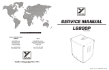
Connect the wiring according to this
diagram. Insert one wire in the PVC
tube (P25), twist the two wires and
cover the joint with the PVC tube.
Fi
g
.8
Make sure the wiring is correct !!!
1. green
2. red
3. yellow
4. red
5 black
KNS2 - 3 - VELLEMAN
/