Milwaukee 8936-20 User manual

Category
Vacuum cleaners
Type
User manual
TO REDUCE THE RISK OF INJURY, USER MUST READ AND UNDERSTAND OPERATOR'S MANUAL.
AFIN DE RÉDUIRE LE RISQUE DE BLESSURES, L'UTILISATEUR DOIT LIRE ET BIEN COMPRENDRE LE
MANUEL DE L'UTILISATEUR.
PARA REDUCIR EL RIESGO DE LESIONES, EL USUARIO DEBE LEER Y ENTENDER EL MANUAL DEL
OPERADOR.
Catalog No.
No de Cat.
Catálogo No.
8950
8955
8936-20
8938-20
HEAVY-DUTY COMMERCIAL VACUUM
EXTRA ROBUSTE ASPIRATEUR COMMERCIAL
HEAVY-DUTY ASPIRADORA COMMERCIAL
OPERATOR'S MANUAL
MANUEL de L'UTILISATEUR
MANUAL del OPERADOR
Page 2
To reduce the risk of fire, electric shock or injury:
1. Do not leave appliance when plugged in. Unplug from outlet when not
in use and before servicing.
2. Do not use outdoors or on wet surfaces.
3. Do not allow to be used as a toy. Close attention is necessary when
used by or near children.
4. Use only as described in this manual. Use only manufacturers recom-
mended attachments.
5. Do not use with damaged cord or plug. If appliance is not working as it
should, has been dropped, damaged, left outdoors, or dropped into
water, return it to a service center.
6. Do not pull or carry by cord, use cord as a handle, close a door on cord,
or pull cord around sharp edges or corners. Do not run appliance over
cord. Keep cord away from heated surfaces.
7. Do not unplug by pulling on cord. To unplug grasp the plug not the cord.
8. Do not handle plug or appliance with wet hands.
9. Do not put any object into openings. Do not use with any opening
blocked; keep free of dust, lint, hair, and anything else that may reduce
air flow.
10. Keep hair, loose clothing, fingers, and all parts of body away from
openings and moving parts.
11. Do not pick up anything that is burning or smoking such as cigarettes,
matches, or hot ashes.
12. Do not use without dust bag and filter in place.
13. Turn off all controls before unplugging.
14. Use extra care when cleaning on stairs.
GENERAL SAFETY RULES
READ AND UNDERSTAND ALL INSTRUCTIONS
Failure to follow all instructions listed below, may result
in electric shock, fire and/or serious personal injury.
SAVE THESE INSTRUCTIONS
WARNING!
READ AND SAVE ALL INSTRUCTIONS
FOR FUTURE USE.
15. Do not use to pick up flammable or combustible liquids such as gasoline
or use in areas where they may be present.
16. Connect to a properly grounded outlet only. See grounding instructions.
17. Vacuum cleaners have motors and other parts that can produce sparks
during normal use. Do not use within 30 feet of areas where explosive
gases may be present (such as gasoline pumps and places where
liquids like paint thinners, cleaners, solvents, etc. are stored).
18. Unplug power cord whenever motor head is removed from tank.
19. Do not use in the presence of explosive liquids or vapors.
20. To reduce the risk of health hazards from vapors or dust, do not vacuum
toxic, carcinogenic or other hazardous materials such as asbestos,
arsenic, barium, berylium, lead, pesticides or other health endangering
materials.
21. Do not use where oxygen or anesthetics are used.
22. Wear electrically insulated footwear, such as rubber boots, when vacu-
uming wet material.
23. WARNING! Some dust created by power sanding, sawing, grinding,
drilling, and other construction activities contains chemicals known to
cause cancer, birth defects or other reproductive harm. Some ex-
amples of these chemicals are:
lead from lead-based paint
crystalline silica from bricks and cement and other masonry prod-
ucts, and
arsenic and chromium from chemically-treated lumber.
Your risk from these exposures varies, depending on how often you
do this type of work. To reduce your exposure to these chemicals:
work in a well ventilated area, and work with approved safety equip-
ment, such as those dust masks that are specifically designed to filter
out microscopic particles.
Page 3
FUNCTIONAL DESCRIPTION
Symbology
Canadian Standards Association
Underwriters Laboratories, Inc.
Hertz
Cat.
No.
8936-20
8938-20
8950
8955
Volts
AC
120
120
120
120
Amps
12*
7.4
8
8
Amps
* For Cat. No. 8936-20 with onboard outlet:
The entire unit is rated at 12 amps. The vacuum motor is rated at 9.5
amps. The outlet on the motor head is rated at 8 amps.
1. Handle
2. Exhaust port
3. Tank latch
4. Intake port
5. Tank
6. Utility Outlet
(Cat. No. 8936-20 only)
1
3
4
5
1
2
2
2
3
3
4
4
5
6
Specifications
Tank
Capacity
Gallons
7.5
9
8
10
Air Flow
Cubic Feet
per Minute
159
102
143
143
For
Materials
Wet or Dry
Wet or Dry
Wet or Dry
Wet or Dry
Sealed
Suction
in Water
59
84
45
45
Page 4
Grounded tools require a three wire extension cord. Double insulated
tools can use either a two or three wire extension cord. As the distance
from the supply outlet increases, you must use a heavier gauge exten-
sion cord. Using extension cords with inadequately sized wire causes a
serious drop in voltage, resulting in loss of power and possible tool
damage. Refer to the table shown to determine the required minimum
wire size.
The smaller the gauge number of the wire, the greater the capacity of the
cord. For example, a 14 gauge cord can carry a higher current than a 16
gauge cord. When using more than one extension cord to make up the
total length, be sure each cord contains at least the minimum wire size
required. If you are using one extension cord for more than one tool, add
the nameplate amperes and use the sum to determine the required mini-
mum wire size.
Guidelines for Using Extension Cords
If you are using an extension cord outdoors, be sure it is marked with
the suffix W-A (W in Canada) to indicate that it is acceptable for
outdoor use.
Be sure your extension cord is properly wired and in good electrical
condition. Always replace a damaged extension cord or have it re-
paired by a qualified person before using it.
Protect your extension cords from sharp objects, excessive heat and
damp or wet areas.
GROUNDING EXTENSION CORDS
Grounded Tools:
Tools with Three Prong Plugs
Tools marked Grounding Required
have a three wire cord and three
prong grounding plug. The plug must
be connected to a properly grounded
outlet (See Figure A). If the tool should
electrically malfunction or break
down, grounding provides a low re-
sistance path to carry electricity
away from the user, reducing the risk
of electric shock.
Improperly connecting the grounding wire can result in the
risk of electric shock. Check with a qualified electrician if you
are in doubt as to whether the outlet is properly grounded.
Do not modify the plug provided with the tool. Never remove
the grounding prong from the plug. Do not use the tool if the
cord or plug is damaged. If damaged, have it repaired by a
MILWAUKEE service facility before use. If the plug will not fit
the outlet, have a proper outlet installed by a qualified
electrician.
Nameplate
Amperes
0 - 5
5.1 - 8
8.1 - 12
12.1 - 15
15.1 - 20
Extension Cord Length
25'
16
16
14
12
10
75'
16
14
12
10
10
100'
14
12
10
10
--
150'
12
10
--
--
--
200'
12
--
--
--
--
Recommended Minimum Wire Gauge
for Extension Cords*
* Based on limiting the line voltage drop to five
volts at 150% of the rated amperes.
50'
16
16
14
12
10
READ AND SAVE ALL INSTRUCTIONS
FOR FUTURE USE.
The grounding prong in the plug is connected through the green wire
inside the cord to the grounding system in the tool. The green wire in the
cord must be the only wire connected to the tool's grounding system and
must never be attached to an electrically live terminal.
Your tool must be plugged into an appropriate outlet, properly installed
and grounded in accordance with all codes and ordinances. The plug
and outlet should look like those in Figure A.
Double Insulated Tools:
Tools with Two Prong Plugs
Tools marked Double Insulated do
not require grounding. They have a
special double insulation system
which satisfies OSHA requirements
and complies with the applicable
standards of Underwriters Labora-
tories, Inc., the Canadian Standard
Association and the National Electri-
cal Code. Double Insulated tools may
be used in either of the 120 volt out-
lets shown in Figures B and C.
WARNING!
Fig. A
Fig. B
Fig. C
Page 5
TOOL ASSEMBLY
Assembling Dolly (Cat. No. 8955) (Fig. 1)
Assemble as shown in the diagram. You will need a hammer and a
phillips screwdriver.
Installing Handle (Cat. No. 8955) (Fig. 2)
You will need either a flat blade screwdriver or a socket driver and a
wrench or a pair of pliers.
Assembling Dolly (Cat. No. 8938-20) (Fig. 3)
Assemble as show in the diagram. You will need: a hammer, two 1/2"
open end wrenches, and two 7/16" open end wrenches.
1. Insert 2-1/2" bolt (M) through the center hole in rear frame (P), attach
lockwasher (L) and nut (K) and tighten securely.
2. Attach support struts (D) to back of rear frame (P) with 5/8" bolt, star
washers, and nuts (finger tight only).
3. Position main frame inside rear frame. Attach with (2) 5/8" bolts and,
star washers, and nuts on each side (G).
4. Attach handle uprights, inside main frame (Q) (make sure that buttons
at the top face inward using 5/8" bolts, star washers and nuts finger
tighten only). Align holes at the top of the struts (D) with hole in the
handle uprights (G). Attach with 1-3/8" bolts, star washers, and nuts
and tighten securely.
5. Go back and tighten the bolts at the bottom of the uprights and struts
(D).
6. Attach caster socket plates (open end down) to front of main frame (R)
using 5/8" bolts, star washers and nuts and insert casters (T) into the
sockets.
7. Attach the handle (A) onto the uprights by pushing down and holding
buttons in.
8. Place tank retaining bracket (J) through the slot in the back of the rear
frame and thread on the knob.
9. Place axle upright on a hard surface and tap a capnut (O) on with a
hammer. Place one wheel on the axle and slide it down to the capnut.
Slide the axle through the rear of frame and slide on the other wheel.
Tap second capnut onto axle after checking that frame is assembled
correctly by placing the tank on the dolly.
10. Slide bumper (U) down over the socket plates until it snaps into place.
11. Hook basket (V) on the handle with the top hooks around the handle
and the bottom prongs in the holes in the handle.
1. Place wheels on rear frame (B) by tapping in the axle (C), fitting the
wheel (D) on the axle and tapping a cap nut (E) on with a hammer.
2. Insert caster socket (G) into front frame (F) and secure it with the
phillips screw (I).
3. Align front frame (F) and rear frame (B) so that they fit together and fit
lip of tank (J) into the grooves in front and rear frames.
4. Secure frame (B and F) to the tank by placing the hex bolts (K) through
the holes in dolly and securing them with nut (N) and washer (M) as
shown.
5. Insert caster (H) into into caster socket (G) and push down until caster
snaps into place.
Fig. 1
A
E
D
C
G
F
H
I
B
J
L
M
N
K
Fig. 2
1. Place dolly handle between tank and side handle on either side of the
tank.
2. Fasten tightly with slotted hex head screws.
Fig. 3
Page 6
Installing and cleaning Cartridge Filters
Attaching Caddy and Casters (Cat. No. 8936-20)
You will only need a Phillips screwdriver.
1. Slide caddy over attaching boss' on bottom of vacuum cleaner tank.
2. Install phillips screws and tighten.
3. Slide caster housings over attaching boss' on bottom of vacuum cleaner
tank.
4. Install phillips screws and tighten.
5. Push caster wheel shafts into attaching holes on bottom of caster
housings and bottom of caddy until they click.
WARNING!
To reduce the risk of injury, always unplug the tool before
removing the motor head.
1. Unplug vacuum cleaner.
2. To remove filter for cleaning, hold onto base
of lid cage with one hand and turn retainer
counter clockwise to loosen (Fig. 4).
Caution: Use care when handling motor
head. Dropping motor head may cause per-
manent damage.
3. Remove filter cartridge from motor head
(Fig. 5). Handle filters carefully when re-
moving for cleaning. Even a small hole can
cause dust to be exhausted. Do not use a
filter with a hole or tear. Replace immedi-
ately.
4. Clean the filter (Fig. 6):
Clean a dry filter cartridge by by tapping
the filter cartridge on the inside of a waste
container or by blowing loose dirt using
exhaust port.
Clean a wet filter cartridge by rinsing it
from the inside. Make sure that the filter is
dry before using it to pick up dry material.
When wet (to prevent mold and/or mildew
build-up), the cartridge filter should be re-
moved and allowed to air dry for a 24-
hour period before being re-installed on
the filter cage.
5. Slide clean cartridge filter over filter cage
(Fig. 7).
6. Place filter retainer on top of cartridge filter.
7. Hold onto base of lid cage with one hand
and turn retainer clockwise to tighten
(Fig. 8).
Installing and cleaning foam filters
1. Unplug vacuum cleaner.
2. Remove motor head.
Caution: Use care when handling motor head. Dropping motor head
may cause permanent damage.
3. Remove the foam filter sleeve (and cloth filter if present) from motor
head.
4. Clean the foam filter
sleeve by rinsing it from
the inside. Make sure that
the filter is dry before us-
ing it to pick up dry mate-
rial. Clean cloth filters by
shaking off loose material
and brushing the filter
with a soft bristle brush
(Fig. 9).
5. Attach the clean foam fil-
ter sleeve to motor head
(Fig. 10).
If you plan to vacuum dry
material into a filter bag,
expand the paper filter
bag and fit cardboard col-
lar onto the intake tube as
far as possible.
If you plan to vacuum dry
material and you are us-
ing the foam filter sleeve,
you must also use the
cloth filter.
6. Replace motor head and
snap down tank latches.
dry materials
wet materials
Fig. 10
Fig. 9
WARNING!
To reduce the risk of injury, always unplug the tool before
removing the motor head.
Fig. 4
Fig. 5
Fig. 6
Fig. 8
Fig. 7
Page 7
Vacuuming wet or dry materials (Fig. 11)
When vacuuming dry materials, either the filter cartridge or the foam filter
sleeve AND the cloth filter are required. There are other filters that can
be used with the required filters to provide additional filtration when
vacuuming dry material. Follow the the instructions included with these
filters. Empty tank and clean filter frequently. Be sure filters are dry
before using the vacuum to pick up dry material. Dry material will clog
wet filters and make them difficult to clean.
When vacuuming wet materials, either the filter cartridge or a foam filter
sleeve is required. A float valve shuts off suction when the tank is full.
Be sure that the float is clean and moves freely in the float cage to
ensure that the float valve works. If you are vacuuming a large amount
of liquid, the filter cartridge can become saturated and a mist can appear
from the exhaust port. If this happens, dry the filter by running the
vacuum (without picking up anything) for 10 minutes.
To reduce the risk of injury: wear safety glasses and a
dustmask when using the vacuum cleaner as a blower.
WARNING!
To reduce the risk of fire, electric shock or injury: Do not plug
any tool or appliance rated over 8 amps into the outlet on the
vacuum cleaner. Check nameplate of the tool for the amp
rating. To reduce the risk of injury, tool must be turned off
before placing switch in the auto position.
WARNING!
OPERATION
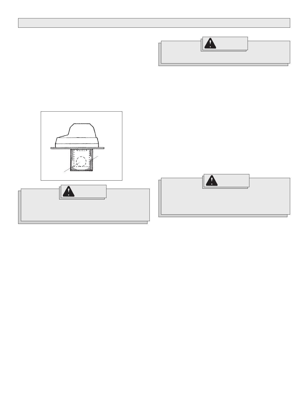
If the float is clean and moves freely and the suction does not
shut off when tank is filled (you will be able to see water in
the exhaust port), send motorhead to the nearest
MILWAUKEE service facility for repair.
WARNING!
Fig. 11
Float cage
Float
Starting and Stopping the Vacuum
To turn vacuum cleaner on, switch the ON/OFF switch to the ON
position.
To turn vacuum cleaner off, switch the ON/OFF switch to the OFF
position.
For Cat. No. 8936-20:
To turn vacuum on, set the AUTO/OFF/ON switch to ON position.
To turn vacuum off, set the AUTO/OFF/ON switch to the OFF position. To
turn the vacuum on automatically by using a tool plugged into the outlet
on the motor head, set the AUTO/OFF/ON switch to the AUTO position.
Removing liquid from the vacuum tank
1. Unplug vacuum cleaner.
2. Remove motor head and set aside.
3. Block wheels.
4. Carefully dump contents into floor drain. Do not dump through intake
tube.
5. Rinse and dry tank.
Do not store vacuum cleaner with liquid in tank. Run the vacuum for
about 10 minutes without picking up anything to dry the inside of the tank
and the filter cartridge.
Using the vacuum as a blower (Cat. Nos. 8950 & 8955 only)
Attach hose to exhaust port on the motor head, attach the
appropriate accessory to the hose, turn the vacuum on.
Using the vacuum cleaner to collect dust created by tools
Many tools (such as sanders) are designed so that they can be used
with vacuum cleaners. The vacuum cleaners collect the dust that these
tools create before it gets into the air or onto the floor. Vacuum cleaners
with the AUTO setting are ideal for collecting dust because they can be
set up to turn on and off automatically by using the tool's on and off
switch. Vacuum cleaners without an AUTO setting can also be used to
collect dust. The operator will simply have to turn the vacuum on and off.
Using the vacuums (without the automatic switch) as dust
collection device for a tool
1. Connect vacuum hose to tool's dust collection port.
2. Turn the vacuum cleaner on.
3. Turn on tool.
To use the vacuum cleaner as an automatic dust collection
device for a tool (with Cat. No. 8936-20 only)
1. Connect vacuum hose to tool.
2. With the power switch in the "O" (Off) position, plug power cord of
the tool (also turned off) into the electrical outlet on the vacuum
cleaner's motor head.
3. Set the AUTO/OFF/ON switch to AUTO. A very brief running opera-
tion of the vacuum will occur. This is normal. Now the vacuum will
operate "On Demand".
4. Turn tool on and the vacuum cleaner will start automatically a few
seconds later. Turn tool off and vacuum will stop automatically a
few seconds later.
Utility Outlet Load - vs - Vacuum Performance
The unique design of the "On Demand" feature of this unit will cause the
vacuum performance to vary with the amount of current drawn from the
utility outlet. The electronic circuit automatically adjusts the power of the
vacuum unit to compensate for the power being drawn from the utility
outlet. This adjustment allows the total system current draw to stay
within the safety regulatory agencies maximum of 12 Amps. What ever
the amount of current is being drawn for utility work, the remainder from
12 Amps is allowed to the vacuum unit to provide the maximum allowable
vacuum performance during the work. As soon as the utility work stops,
the vacuum returns to full power during the delay period before turning
off.
Page 8
Maintaining Tools
Keep your tool in good repair by adopting a regular maintenance pro-
gram. Before use, examine the general condition of your tool. Inspect
guards, switches, tool cord set and extension cord for damage. Check
for loose screws, misalignment, binding of moving parts, improper mount-
ing, broken parts and any other condition that may affect its safe opera-
tion. If abnormal noise or vibration occurs, turn the tool off immediately
and have the problem corrected before further use. Do not use a dam-
aged tool. Tag damaged tools DO NOT USE until repaired
(see Repairs).
Under normal conditions, relubrication is not necessary until the motor
brushes need to be replaced. After six months to one year, depending on
use, return your tool to the nearest MILWAUKEE service facility for the
following:
Lubrication
Brush inspection and replacement
Mechanical inspection and cleaning (gears, spindles, bearings,
housing, etc.)
Electrical inspection (switch, cord, armature, etc.)
Testing to assure proper mechanical and electrical operation
MAINTENANCE
Cleaning
Clean dust and debris from vents. Keep the tool handles clean, dry and
free of oil or grease. Use only mild soap and a damp cloth to clean your
tool since certain cleaning agents and solvents are harmful to plastics
and other insulated parts. Some of these include: gasoline, turpentine,
lacquer thinner, paint thinner, chlorinated cleaning solvents, ammonia
and household detergents containing ammonia. Never use flammable or
combustible solvents around tools.
Repairs
If your tool is damaged, return the entire tool to the nearest service
center.
WARNING!
To reduce the risk of injury, always unplug your tool before
performing any maintenance. Never disassemble the tool or
try to do any rewiring on the tool's electrical system. Contact
a MILWAUKEE service facility for ALL repairs.
WARNING!
To reduce the risk of injury, electric shock and damage to the
tool, never immerse your tool in liquid or allow a liquid to flow
inside the tool.
ACCESSORIES
To reduce the risk of injury, always unplug the tool before
attaching or removing accessories. Use only specifically
recommended accessories. Others may be hazardous.
WARNING!
FIVE YEAR TOOL LIMITED WARRANTY
Every MILWAUKEE tool is tested before leaving the factory and is war-
ranted to be free from defects in material and workmanship. MILWAUKEE
will repair or replace (at MILWAUKEEs discretion), without charge, any
tool (including battery chargers) which examination proves to be defec-
tive in material or workmanship from five (5) years after the date of
purchase. Return the tool and a copy of the purchase receipt or other
proof of purchase to a MILWAUKEE Factory Service/Sales Support
Branch location or MILWAUKEE Authorized Service Station, freight pre-
paid and insured. This warranty does not cover damage from repairs
made or attempted by other than MILWAUKEE authorized personnel,
abuse, normal wear and tear, lack of maintenance, or accidents.
Battery Packs, Flashlights, and Radios are warranted for one (1) year
from the date of purchase.
THE REPAIR AND REPLACEMENT REMEDIES DESCRIBED HEREIN ARE
EXCLUSIVE. IN NO EVENT SHALL MILWAUKEE BE LIABLE FOR ANY
INCIDENTAL, SPECIAL, OR CONSEQUENTIAL DAMAGES, INCLUDING
LOSS OF PROFITS.
THIS WARRANTY IS EXCLUSIVE AND IN LIEU OF ALL OTHER WARRAN-
TIES, OR CONDITIONS, WRITTEN OR ORAL, EXPRESSED OR IMPLIED FOR
MERCHANTABLILITY OR FITNESS FOR PARTICULAR USE OR PURPOSE.
This warranty gives you specific legal rights. You may also have other
rights that vary from state to state and province to province. In those
states that do not allow the exclusion of implied warranties or limitation
of incidental or consequential damages, the above limitations or exclu-
sions may not apply to you. This warranty applies to the United States,
Canada, and Mexico only.
For a complete listing of accessories refer to your MILWAUKEE Electric
Tool catalog or go on-line to www.milwaukeetool.com. To obtain a
catalog, contact your local distributor or a service center.
Page 10
DESCRIPTION FONCTIONNELLE
Pictographie
Canadian Standards Association
Underwriters Laboratories, Inc.
Hertz
Amperes
*Pour le no de cat. 8936-20 avec la sortie de onboard :
L'unité entière est évaluée à 12A. Le moteur de vide est évalué à 9,5A.
La sortie sur la tête de moteur est évaluée à 8A.
1. Poignee
2. Sortie dair
3. Loquet
4. Conduit dadmission
5. Cuve
6. Prise Integree
(No de cat. 8936-20 seul)
1
3
4
5
1
2
2
2
3
3
4
4
5
6
Specifications
No de
cat.
8936-20
8938-20
8950
8955
capacite du
reservoir
(gallons)
7,5
9
8
10
Volts
CA
120
120
120
120
A
12*
7,4
8
8
debit
dair pi.
cu. min.
159
102
143
143
Pour
dechets
sec et humide
sec et humide
sec et humide
sec et humide
aspiration
etanche a
leau
59
84
45
45
58-14-8936d7 04/05 Printed in USA
MILWAUKEE ELECTRIC TOOL CORPORATION
13135 West Lisbon Road Brookfield, Wisconsin, U.S.A. 53005
UNITED STATES
MILWAUKEE Service
MILWAUKEE prides itself in producing a
premium quality product that is
NOTHING BUT HEAVY DUTY
®
.
Your satisfaction with our products is
very important to us!
If you encounter any problems with the
operation of this tool, or you would like to
locate the factory Service/Sales Support Branch
or authorized service station nearest you,
please call...
1-800-SAWDUST
(1.800.729.3878)
NATIONWIDE TOLL FREE
Monday-Friday 8:00 AM - 4:30 PM  Central Time
or visit our website at
www.milwaukeetool.com
For service information, use the 'Service Center
Search' icon found in the 'Parts & Service' section.
Additionally, we have a nationwide network of
authorized Distributors ready to assist you with your
tool and accessory needs. Check your Yellow Pages
phone directory under Tools-Electric for the names
& addresses of those nearest you or see the
'Where To Buy' section of our website.
Corporate After Sales Service - Technical Support
Brookfield, Wisconsin USA
Technical Questions Service/Repair Questions Warranty
1-800-SAWDUST
(1.800.729.3878)
fax:1.800.638.9582
Monday-Friday 8:00 AM - 4:30 PM  Central Time
CANADA
Service MILWAUKEE
MEXICO
Soporte de Servicio MILWAUKEE
Milwaukee Electric Tool, S.A. de C.V.
Blvd. Abraham Lincoln no. 13
Colonia Los Reyes Zona Industrial
Tlalnepantla, Edo. México C.P. 54073
Tel. (55) 5565-1414 Fax: (55) 5565-6874
Adicionalmente, tenemos una red nacional de
distribuidores autorizados listos para ayudarle con
su herramienta y sus accesorios. Por favor, llame
al (55) 5565-1414 para obtener los nombres y
direcciones de los más cercanos a usted, o consulte
la sección Where to buy (Dónde comprar) de
nuestro sitio web en
www.milwaukeetool.com
Notre réseau national de distributeurs agréés se tient
à votre disposition pour fournir laide technique,
loutillage et les accessoires nécessaires. Composez
le 416.439.4181 pour obtenir les noms et adresses
des revendeurs les plus proches ou bien consultez
la section «Où acheter» sur notre site web à ladresse
www.milwaukeetool.com
MILWAUKEE est fier de proposer un produit de
première qualité N
OTHING BUT HEAVY DUTY
®
. Votre
satisfaction est ce qui compte le plus!
En cas de problèmes dutilisation de loutil ou
pour localiser le centre de service/ventes ou le
centre dentretien le plus proche, appelez le...
416.439.4181
fax: 416.439.6210
Milwaukee Electric Tool (Canada) Ltd
755 Progress Avenue
Scarborough, Ontario M1H 2W7
87513-80
  • Page 1 1
  • Page 2 2
  • Page 3 3
  • Page 4 4
  • Page 5 5
  • Page 6 6
  • Page 7 7
  • Page 8 8
  • Page 9 9
  • Page 10 10
  • Page 11 11
  • Page 12 12
  • Page 13 13
  • Page 14 14
  • Page 15 15
  • Page 16 16
  • Page 17 17
  • Page 18 18
  • Page 19 19
  • Page 20 20
  • Page 21 21
  • Page 22 22
  • Page 23 23
  • Page 24 24

Milwaukee 8936-20 User manual

Category
Vacuum cleaners
Type
User manual

Ask a question and I''ll find the answer in the document

Finding information in a document is now easier with AI