Page is loading ...

INSTRUCTION MANUAL
Electronic thermostat
for heating system
MODEL TH135-01
We thank you for trusting Aube technologies and hope that you
will be entirely satisfied.
For any questions concerning the TH135 electronic thermostat,
please call our Technical Support Department at:
Montréal Area:
1-800-831-AUBE (2823)
(450) 358-4600
www.aubetech.com [email protected]
TABLE OF CONTENTS
1. INSTALLATION ............................................1
1.1 Installing a new thermostat . . . . . . . . . . . . . .......................1
1.2 Thermostat installation and electrical hook-up . ....................2
1.3 Thermostat configuration .....................................4
a) Cycles of 15 or 20 minutes . . . . . . . . . . .......................4
b) Regulation modes . . .....................................5
c) Pump protection . . . .....................................6
d) Temperature in °C or °F . . . . . . . . . . . . .......................6
1.4 Battery installation
..........................................
7
2. SETTING THE COMFORT,ECONOMIC AND VACATION TEMPERATURES ......8
3. TELEPHONE CONTROLLER ......................................9
3.1 Connection to the CT240 . . . . . . . ..........................10
3.2 Connection to a house automation system . . . . . . .............11
3.3 Operating the telephone interface ..........................11
4. BATTERY REPLACEMENT ........................................12
5. TECHNICAL SPECIFICATIONS ....................................13
WARRANTY ...................................................14

1
1. INSTALLATION
1.1 INSTALLING A NEW THERMOSTAT
For a new installation, select a position about 5 feet (1.5 m) above the floor, where
there is good air circulation. The thermostat must be installed on an inside partition
wall.
Avoid places where there are:
a) air draughts (the top of a staircase, an air outlet,...)
b) dead air spots (behind a door,...)
c) direct sun rays
d) chimneys or hidden pipes
2
1.2 THERMOSTAT INSTALLATION AND ELECTRICAL HOOK-UP
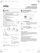
Remove the mounting plate from the thermostat.
A) Undo the screw holding the mounting plate to the thermostat.
B) Lift the lower part of the plate to remove it from the thermostat.
C) Undo the screw holding the wire cover, and remove it.
D) Secure the mounting plate to the wall and do the appropriate connection
(refer to section 2).
A D
B
C
3
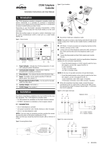
A) Refer to the diagram below for the 2-wire hook-ups. Please note that the
connection can be made on either terminal.
Note:
If you have a CT240 telephone remote control, refer to section 3.1 for hook-up.
WIRES CONNECTION
Hook-up at the furnace thermostat input for hot
water heating, or at the furnace for hot air system
B) Put the wire cover back on.
VAC
3
J5
Hook-up of the circulator for a hot water system or
for a baseboard through a 24 V relay
4
1.3 THERMOSTAT CONFIGURATION
Before installing the thermostat on the wall, it must be set using the dip switches at
the back.
A) Cycles of 15 or 20 minutes
The TH135 offers you heating cycles of 15 or 20 minutes. The
shorter the cycles, the bigger your comfort. However, your system
will be solicited more often.
If you want 15 minute cycles, slide switch #1 upward. If you want
20 minute cycles, slide switch #1 downward.

5
B) Regulation Modes
You have a choice between two regulation modes:
1. Proportional adaptive mode
This mode analyses previous cycles in order to define the length of the upcoming
cycle. This mode guarantees an optimal regulation of 3 cycles (switch #1 to 20
min.) or 4 cycles (switch #1 to 15 min.) per hour, regardless of the season.
2. Conventional mode with anticipation
This mode commands the system's On and Off cycles when the temperature
read by the thermostat reaches pre-set levels. This mode is compatible with all
heating systems. It is recommended for a multi-zone system or for cases
where a thermostat directly controls a furnace equipped with a combustion gas
purge cycle of more than 30 seconds.
Ideal for:
• Radiant or convection electrical heating system
• Circulator control in a hot water system
6
C) Pump protection
For hot water installations, it is recommended to activate
the pump at least one minute every 24 hours in order to
avoid any seizing. Slide switch #3 downward to activate
this function.
For all other installations, let the switch #3 in Off position (or else your system will
be activated 1 minute every 24 hours).
D) Temperature in °C or °F
The TH135 is factory-set in °C. If you wish to change the temperature
display to °F, slide switch #4 upward. Please note that if you change
from °C to °F or vice versa, you must reset the Comfort ( ), Economic
( ) and Vacation ( ) settings accordingly.
7
1.4 BATTERY INSTALLATION
When you first install the batteries in the TH135, the unit runs a
sequence of tests which last approximately 5 seconds. After
the tests, the screen should display the current temperature.
It is normal for the displayed temperature to be higher than the
room temperature if your are holding the TH135 in your hands.
It will return to normal about one hour after installation on
the wall.
Mount the thermostat on the wall plate and screw it in place.
Even if the thermostat indicates that the batteries are good, it is recommended to
replace them once a year
,
at the beginning of the cold season.
1 2 3
8
2. SETTING THE COMFORT, ECONOMIC AND VACATION
TEMPERATURES
1- To set the Comfort temperature, select the desired degree using
the buttons and push the button until the icon is displayed
(about 3 seconds).
2- To set the Economic temperature, select the desired degree using
the buttons and push the button until the icon is displayed
about 3 seconds).
3- To set the Vacation temperature, select the desired degree using
the buttons and push simultaneously the and buttons until the
icon is displayed (about 3 seconds). This setting is used by the
telephone remote control only
.

9
3. TELEPHONE CONTROLLER ( )
The TH135 incorporates a telephone controller interface which allows you to switch
from the or setting to the Vacation setting ( ), and vice versa, using the
telephone keypad (stationary or portable). You can, for example, start the heating of
your country house from your office on Friday, or your house from the airport or from
your car on your way back from vacation.
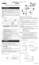
3.1 CONNECTION TO THE CT240
The TH135 is designed to connect
directly to the CT240 telephone
controller. This combination allows
the activation and deactivation of the
Vacation setting from the CT240 or
the telephone.
Connect the CT240’s terminals A
and C to the TH135's terminals X and
C respectively. You must respect the
polarity.
For details on operating the telephone controller, refer
to the CT240’s Instruction Manual.
ABC CX
CT240 TH135
10
11
3.2 CONNECTION TO A HOUSE AUTOMATION SYSTEM
The Vacation setting can also be activated from
a house automation system.
3.3 OPERATING THE TELEPHONE INTERFACE
You can activate the Vacation setting using the Vacation button of the telephone
controller ( ) or using a telephone from outside of the house.
1- To activate the Vacation setting, press the Vacation button of the CT240 ( ).
The Vacation setting will be displayed during 5 seconds and the ( ) icon will
flash on the screen. You no longer have access to the TH135 keypad if
this function is activated by the telephone controller.
2- To deactivate the function and return to the previous setting, press the Vacation
button of the telephone controller again or use a phone from outside of the
house. The red light will go off and the ( ) icon will disappear within a
maximum of 5 seconds.
4. BATTERY REPLACEMENT
The TH135 will display an icon indicating that the
batteries must be replaced. This icon will flash for 60
days. After this delay, the thermostat will shut down
your heating unit.
After the battery replacement, you have to reprogram
the , and settings (refer to section 2).
Even if the thermostat indicates that the batteries are good, it is
recommended to replace them once a year.
12

13
5. TECHNICAL SPECIFICATIONS
Model : TH135-01
Power supply : 2 AA size alkaline batteries
Max. resistive load : 5A @ 30 VAC
5A @ 30 Vdc
Max. inductive load : 2A @ 30 VAC
2A @ 30 Vdc
Auxiliary input : 12 Vcc, +/- 10 %, 20 mA
(telephone interface)
Control device : Electronic
Automatic action: Type 1 B
Storage temperature : -20 °C to 50 °C (-4 °F to 122 °F)
Operating temperature : 0 °C to 50 °C (32 °F to 122 °F)
( 95 % relative humidity without condensation )
Temperature setting range in heating : 5° C to 30 °C (40 °F to 85 °F)
Temperature display scale : 0.1 degree
Temperature reading accuracy : +/- 0.5 °C (+/- 0.9 °F)
Software : class A
Insulation : class
Protection degree: IP 20
The terminals are designed for a range up to 2.5 mm
2
of conductors’section.
14
WARRANTY
This product is guaranteed against workmanship defects for a two-year period
following the initial date of purchase in an authorized retail store. During this period,
AUBE technologies inc. will repair or replace, at its option and without charge, any
defective product which has been used under normal conditions.
The warranty does not cover delivery costs and does not apply to products badly
installed or damaged by accident.
This warranty cancels and replaces any other manufacturer's express or tacit
warranty as well as any other company commitment. AUBE technologies inc.
cannot be held liable for related or random damages following the installation of this
product.
The defective product as well as the purchase invoice must be returned to the place
of purchase or mailed, prepaid and insured, to the following address:
AUBE TECHNOLOGIES INC.
S
ERVICE CENTER
705, Montrichard
Iberville (Quebec)
Canada J2X 5K8
Tel. : (450) 358-4600
Fax : (450) 358-4650
www.aubetech.com
14/08/01 720-135005
/