Allen-Bradley Bulletin 900-TC8VYABZ25 Selection Manual

Category
Power supply units
Type
Selection Manual
SELECTION GUIDE
BULLETIN 900-TC
Single-Loop Electronic
Temperature/Process Controllers
Visit our website: www.ab.com/catalogs
Bulletin 900-TC
Single-Loop Temperature/Process Controller
3
Bulletin 900 Controllers with Enhanced Features
Both the hardware and function set of the Bulletin 900-TC8 and 900-TC16 temperature controller product lines offer an enhanced feature set
as compared to the 900-TC32. The controller enhancements allow the Bulletin 900-TC8 and 900-TC16 line a much wider range of process
applications. Key enhancements include:
ModBus is a registered trademark of Group Schneider.
• Analog voltage and current inputs
• The combination of thermocouple and platinum RTD controller types into one Global Temperature (GT) controller which incorporates both sensor input types
• A second voltage (SSR) or Triac (electronic relay) control output without loss of an alarm output
• 0...20 mA analog output in addition to the existing 4...20 mA output
• Analog transfer output function to allow easy connection to a strip chart recorder or PLC input
• Manual control of the output from the controller keypad, with bumpless transfer to the Automatic PID mode
• 11-segment alphanumeric LED readouts to display the controller parameters in a more understandable format
• Single- and three-phase heater burnout and short circuit detection
• Faster sampling rate to 250 ms
• Direct connection to your PC's USB port and 4-pin serial port on the controller using the 900-CPOEM1 cable. Allows 1-to-1 (non-network) parameter
configuration and monitoring without the need of an option communication unit/module.
• ModBus
®
RTU (master/slave) protocol
Bulletin 900-TC8 and 900-TC16 Series B Added Features and Functions
In addition to the above enhanced features/functions associated with the Bulletin 900-TC8 and 900-TC16 controllers, the Series B version
(released in October 2008) offers additional features over the series A controllers.
MV (Manipulated Variable) Display Yes No
PF Key (addition to keypad: allows one touch assignment of Auto/Manual, Run/Stop, etc) Yes No
Thermocouple Types: Added W and PL II Yes Yes
Thermocouple Accuracy: Improved from +/-0.5% of PV to +/-0.3% of PV Yes Yes
RTD Accuracy: Improved from +/-0.5% of PV to +/-0.2% of PV Yes Yes
Analog Output Resolution: Expanded from 2,700 to 10,000 Yes Yes
Max. Network Communications Rate: Increased to 57.6 Kbps
Yes7
Yes
Simultaneous Network and USB Cable (900-CPOEM1) communications Yes Yes
Modbus Communications: 1 data, 2-byte mode added Yes Yes
Manipulated Variable Limiter Yes Yes
40% Auto-tuning Yes Yes
Auto-tuning for cooling when heating & cooling is selected Yes
Direct/Reverse mode change selection by input interrupt Yes §
Yes
Square Root extraction function for analog input Yes Yes
PV rate of change alarm Yes Yes
Over current alarm Yes
³ Yes ³
9
Version 1.2 of 900BuilderLite is required to configure Series B controllers if the software configuration option is used versus the controller keypad. NOTE:
Version 1.1 saved parameter cannot be downloaded using Version 1.2
7 Requires the use of a communication option unit: 900-TC8232 (Series B) for RS232C or 900-TC8COM (Series B) for RS485 communications.
Requires the use of a Series B RS485 communication option unit: Refer to Table “Option Units”. NOTE: Series A option units cannot be used with Series B
controllers and vice versa.
§ Requires the use of an event Input option unit: 900-TC8EIM (Series B)
Requires the use of a Series B Event Input option unit: Refer to Table “Option Units”. NOTE: Series A option units cannot be used with Series B controllers and
vice versa.
Yes
New Series B Feature/Functionality
9 900-TC8 900-TC16
Bulletin 900-TC Digital Temperature Controllers
Page 4
Bulletin 900-CONV Interface Converter
Page 23
Bulletin 900 900BuilderLite™ Software
Page 26
Bulletin 900 900Builder™ Software
Page 27
Bulletin 900 — Temperature/Process Controllers
³ Requires the use of a current transformer: 900-CT1 or 900-CT2
y Single-Loop, High Value, ON/OFF, or Analog Output Controllers
y 1/8 DIN (Bulletin 900-TC8), 1/16 DIN (Bulletin 900-TC16), and 1/32 DIN (Bulletin 900-TC32)
Sizes
y Various Sensor Inputs
– Thermocouple
– Platinum RTD
– Non-Contact Temperature Sensor
– Analog Input 4...20 mA, 0...20 mA, 1...5, 0...5 or 0...10V DC and 0…50 mV (TC8 and TC16)
y Auto-Tuning and Self-tuning Available to Simplify Startup
y Heating, Cooling, or Heating/Cooling Control Available
y Manual Output Control (TC8 and TC16)
y High Visibility 4-digit, 11-segment LED Displays, Easy to See in High Levels of Ambient Light
y Integral Keypad with Tactile Feedback for Setup and Modification of Parameters
y Security Modes/Levels
y Event Input (TC8 and TC16) for Multiple SP Selection, Controller RUN/STOP and Auto/Manual
Mode Change
y Water-Resistant Construction UL Type 4X or IP66 for Indoor Use
y On-Board Wiring Diagrams to Simplify Startup
y cULus, CE
Visit our website: www.ab.com/catalogs
Bulletin 900-TC
Single-Loop Temperature/Process Controller
4
Product Overview/Quick Selection
Bulletin
900-TC32
Bulletin
900-TC16
Bulletin
900-TC8
Bulletin 900 — Temperature/Process Controllers
Product Selection...... 5
Accessories..................
General Functions .....
7
8
Inputs Ranges............. 10
Specifications.............. 12
Approximate
Dimensions................... 15
Wiring Terminals......... 17
Option Units................. 19
Installation .................... 20
Controller Config.
from Keypad................ 22
Bulletin 900-TCx Quick Selection
Bulletin 900 — Temperature/Process Controllers
Item
Bulletin No.
900-TC8
900-TC16
900-TC32
Dimensions 48 x 96 x 78 mm 48 x 48 x 78 mm 48 x 24 x 100 mm
Alphanumeric Display Types PV, SV, MV PV, SV PV, SV
Sample Rate 250 ms 500 ms
Indication Accuracy
Thermocouple: ±0.3% of PV; RTD: ±0.2% of PV;
Analog: ±0.2% of F.S.
±0.5% PV +1 digit max.
Heating/Cooling Control Mode Yes Yes Yes
Control Method
ON/OFF or 2-PID (auto-tune and self-tune) with time proportioning ON/OFF outputs
or Analog Output (900-TC8 & 900-TC16)
Inputs
Thermocouple Input and 0...50 mV Yes Yes Yes
Platinum Resistance Temperature Sensor Yes Yes Yes
Analog Input 0...20 mA, 4...20 mA,
1...5V DC, 0...5V DC, 0...10V DC
Yes Yes No
Non-Contact Temperature Sensor Yes Yes Yes
Control
Output
1 Type
ON/OFF Relay Output (Electro-
Mechanical)
Yes Yes Yes
ON/OFF Voltage Output for Solid-State
Relay
Yes Yes Yes
ON/OFF Triac (AC Only) No Yes No
4…20 and 0...20 mA (DC) Analog Yes Yes No
Control
Output
2 Types
ON/OFF Relay
No a No a No a
ON/OFF Triac
Yes
³
No No
ON/OFF Voltage SSR
Yes
³
Yes No
Maximum Number of Auxiliary/
Alarm Outputs
None No No
Yes7
1 Output No No Yes
2 Outputs No Yes No
3 Outputs Yes Yes No
RS-232C Communications Function Yes § No No
RS-485 Communications Function Yes § Yes §
Yes ³
Event Input Yes § Yes§ No
Run/Stop via Keypad or Interrupts Yes Yes Keypad
Multiple SP Selection via Keypad or Interrupts
Yes Yes
Keypad
Manual Output Control via Keypad or Interrupts
Yes Yes
No
Transfer Output Function (Requires Analog Output) Yes Yes No
Heater Burnout, Heater Overcurrent or Heater Short Alarm (Single or 3-
Phase)
Yes Yes
No
7 When RS-485 communication is required.
§ Requires an option unit. Refer to Option Unit table on page 6
Interrupts require an event input option unit. Refer to Option Unit table on page 6.
³ Determined by controller catalog number.
a One of the controller alarm relays can be used as a second control output (i.e., a heating and cooling application).
Requires an option unit with an SSR output.
Requires addition of hardware. One current transformer (900-CT1 or 900-CT2) for single-phase and two current transformers for 3-phase detection. For the
900-TC16, the appropriate option unit must be purchased. Refer to Option Units in Product Selection on page 6.
Visit our website: www.ab.com/catalogs
Bulletin 900-TC
Single-Loop Temperature/Process Controller
5
Product Selection
Bulletin 900-TC8 Controller Models
Bulletin
No.
DIN Size
(DImensions)
(mm)
Sensor Input
Type
Power
Supply
Voltage
Max No. of
Auxiliary
Outputs
Supported
³ Control Output 1 Type Control Output 2 Type
Supports
Heater Burnout
(Open) and
Heater Short-
Circuit Alarm
Controller Cat. No.
900-TC8
97
1/8 DIN
48 mm (W)
x 96 mm (H)
x 78 mm (D)
Thermocouple
or RTD
100…
240V AC
3
Relay
—No
900-TC8RGTZ25
Yes (1-Phase) 900-TC8RGTH1Z25
Voltage (for driving SSR) No 900-TC8RVGTZ25
Yes (3-Phase)
900-TC8RGTH3Z25
Voltage (for driving SSR)
—No
900-TC8VGTZ25
Yes (1-Phase) 900-TC8VGTH1Z25
Triac
No
900-TC8VYGTZ25
Voltage (for driving SSR) No 900-TC8VVGTZ25
Yes (3-Phase)
900-TC8VGTH3Z25
0...20 or 4...20 mA
Analog Output
—No
900-TC8ACGTZ25
Triac
No
900-TC8ACYGTZ25
Voltage (for driving SSR) No
900-TC8ACVGTZ25
Thermocouple
or RTD
24V
AC/DC
3
Relay
—No
900-TC8RGTU25
Yes (1-Phase) 900-TC8RGTH1U25
Voltage (for driving SSR)
—No
900-TC8VGTU25
Yes (1-Phase)
900-TC8VGTH1U25
0...20 or 4...20 mA
Analog Output
—No
900-TC8ACGTU25
Analog Current
& Voltage 0...20
and 4...20 mA
0...5, 1...5, and
0...10V DC
100…
240V AC
3
Relay Yes (1-Phase)
900-TC8RABH1Z25
Relay No
900-TC8RABZ25
Voltage (for driving SSR) Yes (1-Phase)
900-TC8VABH1Z25
Voltage (for driving SSR) No
900-TC8VABZ25
Voltage (for driving SSR)
Triac
No
900-TC8VYABZ25
0...20 or 4...20 mA
Analog Output
—No
900-TC8ACABZ25
Bulletin 900-TC16 Controller Models
Bulletin
No.
DIN Size
(DImensions)
(mm)
Sensor Input
Type
Power
Supply
Voltage
Max No. of
Auxiliary
Outputs
Supported
³ Control Output Type §
Supports Heater
Burnout (Open)
and Heater
Short-Circuit
Alarm Controller Cat. No.
900-TC16
97
1/16 DIN
48 mm (W)
x 48 mm (H)
x 78 mm (D)
Thermocouple
or RTD
100…
240V AC
2
Relay Output Yes
900-TC16RGTU25
Triac
Yes
900-TC16YGTZ25
Voltage output (for driving SSR) Yes 900-TC16VGTZ25
0...20 or 4...20 mA Analog Output No 900-TC16ACGTZ25
Thermocouple
or RTD
24V
AC/DC
2
Relay Output Yes
900-TC16RGTU25
Voltage output (for driving SSR) Yes 900-TC16VGTU25
0...20 or 4...20 mA Analog Output No 900-TC16ACGTZ25
Analog Current
& Voltage 0...20
and 4...20 mA
0...5, 1...5, and
0...10V DC
100…
240V AC
2
Relay Yes
900-TC16RABZ25
Triac
Yes
900-TC16YABZ25
Voltage (for driving SSR) Yes
900-TC16VABZ25
0...20 or 4...20 mA Analog Output No
900-TC16ACABZ25
24V
AC/DC
Relay Yes
900-TC16RABU25
Voltage (for driving SSR) Yes 900-TC16VABU25
0...20 or 4...20 mA Analog Output No
900-TC16ACABU25
9 A current transformer (CT) is not provided with the unit.
7 When the heating and cooling function or the heater burnout alarm is used, one of the relay alarm outputs can be used as the heating or cooling output or
heater burnout alarm.
To implement the single-phase or three-phase heater burnout and heater short alarm function, an option module must be inserted into the 900-TC16 controller.
For a list of 900-TC16 option modules, refer to the Option Units table, page 6. The heater burnout and heater short alarm is available by mounting the
appropriate option module into any 900-TC16 controller that supports (yes) the heater burnout (open) or heater short-circuit feature.
§ The Bulletin 900-TC16 can have a second ON/OFF control output (SSR) by adding an option unit to the controller. Refer to Option Units table on page 6.
For AC voltage operation only
³ Typically used for alarms or cooling output in a heat/cool application
Visit our website: www.ab.com/catalogs
Bulletin 900-TC
Single-Loop Temperature/Process Controller
6
Product Selection
Bulletin 900-TC32 Standard Controller Models
Bulletin
No.
DIN Size
(DImensions)
(mm)
Power
Supply
Voltage
Max No. of
Alarms
Supported
³ Control Output Type
Supports
Heater
Burnout
(Open) and
Heater Short-
Circuit Alarm
Controller Cat. No.
with Thermocouple
Support
Controller Cat. No.
with Platinum RTD
Support
900-TC32
97
1/32 DIN
48 mm (W) x 24 mm
(H) x 100 mm (D)
100…
240V AC
1
Relay Output
No
900-TC32RTZ25 900-TC32RPZ25
Voltage output (for driving SSR) 900-TC32VTZ25 900-TC32VPZ25
24V AC/DC 1
Relay Output
No
900-TC32RTU25 900-TC32RPU25
Voltage output (for driving SSR)
900-TC32VTU25 900-TC32VPU25
100…
240V AC
RS485
Relay Output
No
900-TC32CRTZ25 900-TC32CRPZ25
Voltage output (for driving SSR)
900-TC32CVTZ25 900-TC32CVPZ25
24V AC/DC RS485
Relay Output
No
900-TC32CRTU25 900-TC32CRPU25
Voltage output (for driving SSR) 900-TC32CVTU25 900-TC32CVPU25
9 If the heating/cooling function is used, ALM1 will be used for the cooling control output and so the alarm output relay will not be available.
7 Cat. Nos. with a C designator (e.g., Cat. No. 900-TC32C___) include RS-485 communications, but do not have an alarm (or cooling) output.
³ Typically used for alarms or cooling output in a heat/cool application
Option Units (Bulletins 900-TC8 and 900-TC16 — Only One Option Unit per Controller)
The unit provides communications or event input functionality.
Bulletin No. Name Function Cat. No.
900-TC8
Communications Unit
RS-232C communications
900-TC8232(B)
RS-485 communications
900-TC8COM(B)
Event Input Unit
Event inputa
900-TC8EIM
900-TC16
Communications and 1-Phase Heater
Burnout Unit and Heater Short
RS-485 communications with single-phase heater burnout (open) and heater
short-circuit failure detection
900-TC16NCOM(B)§
Event Input Unit with 1-Phase Heater
Burnout and Heater Short
Event Input with single-phase heater burnout (open) and heater short-circuit
failure detectiona
900-TC16NEIM(B)
Event Input Unit
Event Inputa
900-TC16NACEIM(B)
Communications Unit RS-485 communications
900-
TC16NACCOM
(B)§
Communications and 3-Phase Heater
Burnout and Heater Short Unit
RS-485 communications with 3-phase heater burnout (open) and heater short-
circuit failure detection
900-
TC16NCOMP3
(B)§
Communications and Second Voltage
(SSR) Output Unit
RS-485 communications and a second voltage (SSR) output
900-
TC16NCOMV2
(B)§
1-Phase Heater Burnout and second
voltage (SSR) output
1-Phase Heater burnout (open) and heater short-circuit failure detection with a
second control voltage (SSR) output
900-TC16P1V2(B)
Enables direct RS-232 connection to personal computer using 900BuilderLite™ software. A Cat. No. 900-CP1X cable or equivalent is also required.
a Provides two event inputs. Allows selecting up to 4 different pre-configured set points, controller Run/Stop or Auto/Manual mode, from 2 external inputs.
Heater burnout is not available for 0...20 or 4…20 mA analog output style 900-TC16 controllers such as the 900-TC16AC.
To obtain 57.6 k baud rate, Series B communication units must be used with any 900-TC8 controller catalog number from the Product Selection table on the
previous page.
Series B option units must be used with Series B 900-TC16 controllers. Series A option units cannot be used with Series B controllers and vice versa.
§ Series B provides 57.6 K baud rate.
Visit our website: www.ab.com/catalogs
Bulletin 900-TC
Single-Loop Temperature/Process Controller
7
Accessories
Accessories
For Use With Bulletin No. Hole Diameter Cat. No.
900-TC8, 900-TC16
5.8 dia.
900-CT1
12.0 dia. 900-CT2
The hole diameter is the only functional difference between the Cat. No. 900-CT1 and the Cat. No. 900-CT2. Current output to controller is the same.
Interface Converter (RS-232/USB to RS-485) Model
Converts personal computer RS-232 or USB (Ser. B or later) communications to RS-485. Use for interface with a single Bulletin 900-TC8, or
Bulletin 900-TC16 with a Cat. No. 900-TCxxCOM unit installed or a single Cat. No. 900-TC32C_ designated controller. Also allows interface
to up to 31 controllers connected on a RS-485 link/network. See Bulletin 900-CONV, page 24 for additional details.
Bulletin No. Size Power Supply Voltage Cat. No.
900-CONV 30 mm (W) x 80 mm (H) x 78 mm (D)
100…240V AC
900-CONVZ25
24V AC/DC 900-CONVU25
RS-232 Interface Cable
Allows connection between a 900-TC8 with a 900-TC8232 option unit and a PC using 900BuilderLite software (see page 25) or PC with
software and a 900-CONV RS232-to-RS485 converter (see Bulletin 900-CONV, page 24).
900Builder™ Personal Computer Configuration Software (for Bulletin 900-TC32 Controllers)
Allows online and offline graphical configuration and online (direct or network) monitoring of controller parameters with data-logging and
trending, plus program upload/download capability for any Bulletin 900-TC32 controller.
Accessory Cat. No.
900Builder™ Personal Computer Configuration Software for Bulletin 900-TC32 Temperature Controllers (available in CD format only)
900-BLDSW1
Current Transformer (Use with Bulletins 900-TC8 and 900-TC16 Only for Heater Burnout or Heater Short)
USB Direct Communication Cable
This cable allows direct 1-to-1 (no network capability) communication between a PC USB port and the serial port of a Bulletin 900-TC16 or a
900-TC8 controller. No communication option unit is required. The cable can be used with the 900BuilderLite™ software to modify
parameters, monitor controller operation, and upload or download parameters to/from PC disk media.
Accessory Cat. No.
RS-232 cable with 9-pin female D shell and 3 flying leads (3 m)
900-CP1X
Accessory Cat. No.
USB-Serial Conversion Cable
900-CPOEM1
900BuilderLite™ Personal Computer Configuration Software for Bulletin 900-TC8 and 900-TC16 Controllers
Accessory Cat. No.
Free configuration software for Enhanced Functionality Bulletin 900-TC8 and 900-TC16 controllers.
900-BLDLTSW1
Free software. Allows online configuration and monitoring (direct or network) plus program upload/download capability to/from PC disk media
for any Bulletin 900-TC8 or 900-TC16 controller.
Note 1: To obtain the free software, go to http://www.ab.com and use the A-Z Product Directory under "Resources" to locate the Temperature
Controller home page. With the Bulletin 900-TC Single-Loop website displayed, go to the "Get Software" selection in the upper right and click
on 900BuilderLite. Follow the download instructions.
Note 2: Version 1.2 of 900BuilderLite is required to configure Series B controllers. Version 1.1 saved parameter cannot be downloaded to a
Series B controllers using Version 1.2.
Visit our website: www.ab.com/catalogs
Bulletin 900-TC
Single-Loop Temperature/Process Controller
8
Bulletin 900-TC8
General Functions
USB-Serial Conversion Cable (900-CPOEM1)
(2,100)
250
1,765
USB connector (type A plug) Serial connector
LED indicator
(
RD
)
LED indicator (SD)
y Note: To use the cable you must first download a USB driver (free download). To get the driver, go to http://www.ab.com and use the A-Z
Product Directory under "Resources" to locate the Temperature Controller home page. When the Bulletin 900-TC Single-Loop Controller
website is displayed, go to "Get Software" selection in the upper right and click on 900-CPOEM1 driver. Follow the instructions.
y Do not connect or disconnect the Conversion Cable connector repeatedly over a short period of time. The computer may malfunction.
y After connecting the Conversion Cable to the computer, check the COM port number before starting communications. The computer
requires time to recognize the cable connection. This delay does not indicate failure.
y Do not connect the Conversion Cable through a USB hub. Doing so may damage the Conversion Cable.
y Do not use an extension cable to extend the Conversion Cable length when connecting to the computer. Doing so may damage the
Conversion Cable.
6. MANU (Manual Mode) — Lights when the controller mode
is in manual.
7. (Key) — Lights when thesettings change protection
is ON ( Keys disabled).
Green, , Amber
A
2(
#/
MV
SV
PV
57$
57$
5612176
/#07
%/9176
57$
*#
auxiliary 1 output is ON
auxiliary 2 output is ON
auxiliary 3 output is ON
SUB 1
SUB 2
SUB 3
No. 3 Display (Amber)
Displays manipulated variable soak time
remaining or multi SP.
No. 2 Display (Green)
Displays the set point, manipulated variable, or
configured value (setup) of the parameter.
4-pin Serial Port For USB Cable (900-CPOEM 1)
Visit our website: www.ab.com/catalogs
Bulletin 900-TC
Single-Loop Temperature/Process Controller
9
General Functions, Continued
Bulletin 900-TC16
Bulletin 900-TC32
SUB
SUB
, or Amber
6. MANU (Manual Mode) — Lights when the controller mode
is in manual.
7. (Key) — Lights when thesettings change protection
is ON ( Keys disabled).
failure (open or short)
A
SUB2 — Lights when auxiliary 2 output is ON.
SUB1 — Lights when auxiliary 1 output is ON.
4Pin Serialport
configured value (setup) of the parameter.
Visit our website: www.ab.com/catalogs
Bulletin 900-TC8 and 900-TC16
Global Temperature (Thermocouple/RTD) and Analog Ranges and Selections
10
Temperature Sensor Input Ranges (In Degrees C)
Controllers with Analog Inputs
Input Type Current Voltage
Input Specification 4...20 mA 0...20 mA 1...5V DC 0...5V DC 0...10V DC
Setting Range
Usable in the following ranges by scaling:
-1999...9999, -199.9...999.9, -19.99...99.99 or -1.999...9.999
Setting Number 01234
Shaded area is the default setting for analog input type (AB) 900-TC8xAB or 900-TC16xAB controllers.
Bulletin 900-TC8 and 900-TC16
Input
type
Platinum resistance
thermometer
Thermocouple
Infrared temperature
sensor
Analog
input
Name Pt100 JPt100 K J T E L U N R S B W
PL
II
10 to
70°C
60 to
120
°C
115
to
165
°C
140
to
260
°C
0 to
50 mV
Temperature range (°C)
2300
1800
1700
1600
1500
1400
1300
1200
1100
1000
900
800
700
600
500
400
300
200
100
0
100.0
200.0
2300
Usable
in the
following
ranges
by
scaling:
1999 to
9999 or
199.9
to 999.9
1800
1700 1700
003100310031
058058058
600
500.0 500.0 500.0
400.0 400 400.0 400 400.0
260
120 165
100.0 100.0 90
100
0.0 0.0 00 00 0 0 0 0
20.0 100 20.0 100
200 199.9 199.9 200 200 199.9 200 200 199.9 200
Setting
number
01234
5 6 7 8 9 10 11 12 13 14 15 16 17 18 24 25 19 20 21 22 23
900-TC8 and 900-TC16 Input Ranges
9 Applicable standards by input type are as follows:
K, J, T, E, N, R, S, B: JIS C1602-1995
L: Fe-CuNi, DIN 43710-1985
U: Cu-CuNi, DIN 43710-1985
W:W5Re/W26Re, ASTM E998-1990
PLII: According to Platinel ll electromotive force charts from BASF (previously Engelhard)
7 JPt100: JIS C1604-1989, JIS C1606-1989
Pt100: JIS C1604-1997, IEC 751
The non-contact temperature sensor must be configurable for type K thermocouple output within either of the four specified ranges. For example, an OMRON
ES1A or Calex EL Series (Convir) infrared sensor.
§ Shaded setting number indicates default setting for thermocouple or platinum RTD type 900-TC8xGT or 900-TC16xGT controllers.
Visit our website: www.ab.com/catalogs
Bulletin 900-TC32
Thermocouple/RTD Ranges and Selections
11
Input Ranges (In Degrees C)
Applicable standards by input type are as follows:
K, J, T, E, N, R, S, B: JIS C1602-1995
L: Fe-CuNi, DIN 43710-1985
U: Cu-CuNi, DIN 43710-1985
7 JPt100: JIS C1604-1989, JIS C1606-1989
Pt100: JIS C1604-1997, IEC 751
The non-contact temperature sensor must be configurable for type K thermocouple output within either of the four specified ranges. For example, an OMRON
ES1A or Calex EL Series (Convir) infrared sensor.
§ Shaded areas indicate default setting for thermocouple (900-TC32xT) or platinum RTD (900-TC32xP) type 900-TC32 controllers.
§
§
900-TC32 Input Ranges
Visit our website: www.ab.com/catalogs
Bulletin 900-TC
Single-Loop Temperature/Process Controller
12
Specifications
Bulletins 900-TC8, 900-TC16, and 900-TC32
Technical/Control Ratings
Supply Voltage (Line) 100…240V AC, 50/60 Hz 24 V AC, 50/60 Hz or, 24 V DC
Operating Voltage Range (Line) 85…110% of rated supply voltage
Power
Consumption
900-TC8 5.4 VA @120V AC, 9 VA @ 240V AC 5 VA @ 24 V AC, 4 W @ 24 V DC
900-TC16 3.0 VA @120V AC, 7.5 VA @ 240V AC 4 VA @ 24 V AC, 3 W @ 24 V DC
900-TC32 4.3 VA @ 120V AC, 7 VA @ 240V AC 4 VA @ 24 V AC, 2.5 W @ 24 V DC
Temperature
Input
Thermocouple
J, K, T, E, L, U, N, R, S, B [also W and PL11 for 900-TC8x & 900-TC16x] (controller applies cold junction
compensation)
Platinum Resistance
Thermometer
Pt100, JPt100 (controller RTD excitation current: approx. 1 mA) 2- or 3-wire configuration
Non-Contact Temperature
Sensor
10…70 °C, 60…120 °C, 115…165 °C, 140…260 °C
MIllivolt Input 0…50 mV
900-TC8 and
900-TC16
Analog Voltage Input 1...5V DC, 0...5V DC and 0...10V DC
Analog Current Input 4...20 mA and 0...20 mA
Analog Input
Impedance
Current Input:
150 Ω max.
Voltage:
1 MΩ min.
Control
Output
Electro-mechanical
Relay output
900-TC8
SPST-NO, 250V AC @ 5 A, 30V DC @ 10 A (max. resistive load), electrical life: 100 000 operations, min. load 5V,
10 mA
900-TC16
SPST-NO, 250V AC @ 3 A, 30V DC @ 10 A (max. resistive load), electrical life: 100 000 operations, min. load 5V,
10 mA
900-TC32 SPST-NO, 250V AC @ 2 A, 30V DC @ 2 A (max. resistive load), electrical life: 100 000 operations
Voltage output
(SSR compatible)
900-TC8
12V DC +15%/-20% (PNP), max. load current: 40 mA, with current limit protection Output 2 max. load current
21 mA
900-TC16 12V DC ±15% (PNP), max. load current: 21 mA, with current limit protection
900-TC32 12V DC (PNP), max. load current: 21 mA, with current limit protection
Triac output (AC
only)
900-TC8 SPST-No, 250V AC @ 3 A (max. resistive load)§
900-TC16 SPST-NO, 250V AC @ 3 A (max. resistive load)§
900-TC32 NA
Analog Output
900-TC8 DC: 4...20 mA, 0...20 mA, max. load 600 ohms, resolution 10,000
900-TC16 DC: 4...20 mA, 0...20 mA, max. load 600 ohms, resolution 10,000
900-TC32 NA
Auxiliary
Output
900-TC8, 900-TC16
SPST-NO, 250V AC @ 3 A, 30V DC @ 5 A (max. resistive load), electrical life: 100 000 operations, min. load 1V,
1 mA
900-TC32
SPST-NO, 250V AC @ 1 A, 30V DC @ 2 A (max. resistive load), electrical life: 100 000 operations, min. load 1V,
1 mA
Event Input
Contact
ON: 1K Ω (max.)
OFF: 100K Ω (min.)
Non-contact
ON: Voltage Drop 1.5V (max.)
OFF: Leakage current 0.1 mA (max.)
Control Method ON/OFF control or 2-PID (auto-tune and self-tune)
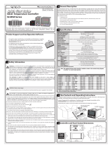
Configuration Method
Digital configuration using front panel keys or 900BuilderLite software for 900-TC8x and 900-TC16x, 900Builder
software for 900-TC32x
Indication Method
11-segment digital display and individual indicators: Bulletin 900-TC8 and 900-TC16. 7-segment for Bulletin
900-TC32
Character
Height
900-TC8 Process Value Display: 11.8 mm; Set Point Display: 8.1 mm; MV Display: 5.8
900-TC16 Process Value Display: 11 mm; Set Point Display: 6.5 mm
900-TC32 Process Value Display: 7.0 mm; Set Point Display: 3.5 mm
Indication
Accuracy
Thermocouple
900-TC8 and 900-TC16 ±0.3 % of indicated value, 900-TC32 ±0.5% of indicated value or ±1°C, whichever
greater ±1 digit max. 7
Platinum Resistance
Thermometer (RTD)
900-TC8 and 900-TC16 ±0.2 % of indicated value, 900-TC32 ±0.5% of indicated value or ±1°C, whichever
greater ±1 digit max.
Analog Input (900-TC8, 900-
TC16)
±0.2% FS±1 digit max.
CT Input (900-TC8, 900-TC16)
±5% FS±1 digit max.
Affect of Signal Source Resistance
Thermocouple: 0.1°C/ohm max. (100 ohm max.)
Platinum RTD: 900-TC8 and 900-TC16, 0.1°C/ohm max., 900-TC32, 0.4°C/ohm max. (10 ohm max.)
9 Unless noted, specifications apply to Bulletins 900-TC8, 900-TC16, and 900-TC32.
7 The indication of K thermocouples in the –200…+1300 °C range, and T and N thermocouples at a temperature of –100 °C or less, and U and L thermocouples
at any temperature is ±2 °C ±1 digit maximum. The indication of B thermocouples at a temperature of 400 °C or less is not specified. The indication of R and S
thermocouples at a temperature of 200 °C or less is ±3 °C ±1 digit maximum.
Applies to 900-TC8 or 900-TC16.
§ Electrical life: 1 million operations, Load Power Supply voltage: 75 to 250V AC (NA DC), Minimum Load: 5V, 10 mA, Leakage Current:5 mA at 250V AC 60 Hz.
900-TC8 and 900-TC16, 0.1°C/ohm max. for all thermocouple types, 900-TC32,B, R, and S sensors: 0.2° C/ohm max. (100 ohm max.)
Visit our website: www.ab.com/catalogs
Bulletin 900-TC
Single-Loop Temperature/Process Controller
13
Bulletins 900-TC8, 900-TC16, and 900-TC32, Continued
Weight (includes carton)
900-TC8 Approx. 360 g (12.7 oz.) with mounting bracket
900-TC16 Approx. 160 g (5.6 oz.) with mounting bracket
900-TC32 Approx. 160 g (5.6 ounces)
900-TC8232, COM, EIM Approx. 20 g (0.7 ounces)
900-TC16COM, EIM Approx. 35 g (1.2 ounces)
Ambient Temperature –10…+55 °C (with no condensation or icing)
Ambient Humidity 25…85%
Storage Temperature –25…+65 °C (with no condensation or icing)
Insulation Resistance
20 MΩ min. (at 500V DC)
Dielectric Strength 2300V AC, 50 or 60 Hz for 1 min. (between terminals with different charge)
Maximum Operating Vibration 10…55 Hz, 20 m/s
2
(2 G) for 10 minutes each in X, Y, and Z directions
Maximum Shock Operating 100 m/s
2
(10 G), 3 times each in X, Y, and Z directions.
Protective Structure
Front panel: Type 4X (UL 50)
9 IP66 (IEC61010-1)
Rear case: IP20, Terminals: IP00
Installation Environment Installation category II, pollution class 2 (IEC 61010-1 compliant)
Memory Protection EEPROM (non-volatile memory) (number of writes: 100 000)
EMC
EMI EN 61326
Radiated Interference Electromagnetic
Field Strength
EN 55011 Group 1, class A
Noise Terminal Voltage EN 55011 Group 1, class A
EMS EN 61326
ESD Immunity EN 61000-4-2
Electromagnetic Field Immunity EN 61000-4-3
Burst Noise Immunity EN 61000-4-4
Conducted Disturbance Immunity EN 61000-4-6
Surge Immunity EN 61000-4-5
Power Frequency Magnetic Field
Immunity
EN 61000-4-8
Voltage Dip/Interrupting Immunity EN 61000-4-11
Conformed Standards
General/Environmental Ratings
Conforms to EN61010-1, IEC 61010-1, and VDE 0106/part 100 (finger
protection) when the terminal cover is installed, Pollution Level 2, Overcurrent
Category II
Technical/Control Ratings
Influence of Ambient
Temperature and Line
Voltage
y R, S, B, W, PL II Thermocouple Inputs: ±1% of PV or ±10°C, whichever is great, ±1 digit max.
y Other Thermocouple Inputs: ±1% of PV or ±4°C, whichever is greater ±1 digit max. Note: For a Type-K thermocouple for -100°C
or less ±10°C
y RTD Sensors: ±1% of PV or ±2°C, whichever is greater. ±1 digit max.
y Analog Inputs: ±1% of full scale ±1 digit max.
Hysteresis (Controller with
Temperature Inputs)
0.1…999.9 EU (in units of 0.1 EU)
³
Hysteresis (Controller with
Analog Inputs)
0.01 to 99.99% FS (in units of 0.01% Full Scale)
Proportional Band (P)
Controller with Temperature
Inputs
0.1…999.9 EU (in units of 0.1 EU)
³
Proportional Band Controller
with Analog Inputs
0.1 to 999.9% FS ( in units of 0.1% FS)
Integral Time (I) 0…3999 s (in units of 1 s)
Derivative Time (D)
0…3999 s (in units of 1 s)a
Control Period 0.5, 1…99 s (in units of 1 s)
Manual Reset Value 0.0…100.0% (in units of 0.1%)
Alarm Setting Range –1999…+9999 (decimal point position depends on input type)
Sampling Period 250 or 500 ms (900-TC8 or 900-TC16), 500 ms (900-TC32)
Other Functions According to Controller model
³ Engineering Unit (EU) is used as the unit after scaling. For a temperature sensor, the EU is °C or °F.
a When Robust Tuning (RT) is on, the differential is is 0.0... 999.9 in units of 0.1 sec.
Conditions: Ambient temperature: -10°C to 23°C to 55°C. Voltage Range: -15% to +10% of rated voltage.
9 The temperature controller is mounted on the flat surface of an enclosure that is rated and marked "Type 4X for Indoor Use Only"
Specifications, Continued
Visit our website: www.ab.com/catalogs
Bulletin 900-TC
Single-Loop Temperature/Process Controller
14
Specifications, Continued
Bulletins 900-TC8, 900-TC16, and 900-TC32, Continued
Current Transformer (Sold Separately) Ratings (Use with Bulletins 900-TC8 and 900-TC16 Only)
Dielectric Strength 1000V AC (1 min.)
Vibration Resistance 50 Hz 98 m/s
2
(10 G)
Weight (includes carton)
900-CT1 Approx. 19 g (0.67 ounces)
900-CT2 Approx. 65 g (2.3 ounces)
Heater Burnout and Heater Short-Circuit Failure Alarm (Use with Bulletins 900-TC8 and 900-TC16 Only—Current Transformer Required)
Max. Heater Current Single-Phase AC 50 A
Input Current Readout Accuracy ±5%FS ±1 digit max.
Alarm Setting Range 0.1…49.9 A (0.1 A units)
Min. Detection ON Time 100 ms §
Approved Standards
Standards
NEMA/EEMAC ICS 2 (Industrial Controls and Systems)
UL 61010-1, CSA C22.2 No. 1010.1
§ When the heater ON/OFF time is less than 100 ms, heater current cannot be measured and the heater burnout alarm (ON) or SSR failure alarm (OFF) will not activate.
Applicable OS Windows 2000, XP or Vista
Applicable Configuration Software 900BuilderLite
Applicable Models 900-TC8 and 900-TC16
USB Interface Standard Conforms to USB Specification 1.1
Power Supply Voltage 5V DC
Current Consumption 70 mA
Ambient Operating Temperature 0...55°C (with no condensation or icing)
Ambient Operating Humidity 10%...80%
Storage Temperature -20...-60°C (with no condensation or icing)
Storage Humidity 10%...80%
Transmission Path Connection RS485 Multiple points
Communications Method
9
900-TC8 RS-232C or RS-485 (2-wire, half duplex)
900-TC16 RS-485 (2-wire, half duplex)
900-TC32 RS-485 (2-wire, half duplex)
Synchronization Method Start-stop synchronization
Protocol 900TC or Modbus RTU Slave
Baud Rate 7
1200/2400/4800/9600/19 200, 38400 bps, 57600 (900-TC8 and -TC16)
Data Bit Length 7
7 or 8 bits
Stop Bit Length 7
1 or 2 bits
Error Detection Vertical Parity (None, even, odd) BCC or with ModBus CRC-16
Flow Control Not available
Interface
900-TC8
9
RS-485/RS-232C
900-TC16
9
RS-485
900-TC32
9
RS-485
Retry Function Not available
Communications Response Wait Time 0...90 ms (Default: 20 ms)
Communications Buffer 900-TC8 and TC-16, 217 bytes
9 RS-232C communications is only supported for Bulletin 900-TC8 (Cat. No. 900-TC8232 option board installed). All controllers support RS-485 communications
(32 linked/networked devices) by appropriate option unit or correct controller catalog number.
7 The baud rate, data bit length, stop bit length, or vertical parity can be individually set using the communications configuration function group.
Communications
Power Supply Bus Power (Supplied from USB host controller)
DTE Speed 38400 bps
Connector Specifications
Computer: USB (type A plug)
Temperature Controller : 3-pin Serial
Altitude 2000 m max.
Weight Approx. 100 g
USB-Serial Cable (900-CPOEM1)
Note: A USB driver (available for free from Allen-Bradley) must be installed in the personal computer before the cable can be used.
B, R, and S series: 0.2°C/Ohm max. (100 Ohm max.)
When the configured value of the alarm is 00 A, the alarm will always be OFF for heater burnout and ON for SSR failure. When the configured value is 50.0 A,
the heater burnout alarm will always be ON and the SSR failure will be OFF.
Visit our website: www.ab.com/catalogs
Bulletin 900-TC
Digital Temperature Controller
15
Approximate Dimensions
Approximate dimensions are shown in millimeters unless otherwise indicated (to convert to inches, multiply by 0.0394). Dimensions are not to
be used for manufacturing purposes.
Bulletin 900-TC8
Panel Cutouts
y Recommended panel thickness is 1…8 mm.
y Group mounting is not possible in the vertical direction. (Maintain
the specified mounting space between controllers when they are
group mounted. UL Type 4X is not possible when group
mounting.)
y To mount the unit so that it is waterproof, apply the waterproof
gasket to the unit
y When two or more units are mounted together, make sure that the
surrounding ambient temperature does not exceed the allowable
operating temperature specification.
Safety Terminal Cover9
Bulletin 900-TC16
Panel Cutouts
y Recommended panel thickness is 1…5 mm.
y Group mounting is not possible in the vertical direction. (Maintain
the specified mounting space between Controllers when they are
group mounted. IP66 UL Type 4X is not possible when group
mounting.)
y To mount the unit so that it is waterproof, apply the waterproof
gasket to the unit.
y When two or more units are mounted together, make sure that the
surrounding ambient temperature does not exceed the allowable
operating temperature specification.
Safety Terminal Cover
9
9 Conforms to VDE 0106 (finger protection) when installed on the controller.


2(
#/
MV
SV
PV
57$
57$
5612176
/#07
%/9176
57$
*#
10
1.2 3.2
44.8
6
99
91
44.8 × 44.8
48.8
6
1.5
91
78
58
Visit our website: www.ab.com/catalogs
Bulletin 900-TC
Digital Temperature Controller
16
Approximate Dimensions, Continued
Approximate dimensions are shown in millimeters unless otherwise indicated (to convert to inches, multiply by 0.0394). Dimensions are not to
be used for manufacturing purposes.
Bulletin 900-TC32
Panel Cutouts
y Recommended panel thickness is 1…5 mm.
y When carrying out maintenance on the unit, the I/O wiring
terminal block can be removed from the module with the
terminal leads still attached.
y Group mounting is not possible in the vertical direction.
(Maintain the specified mounting space between controllers
when they are group mounted. IP66 UL Type 4X is not
possible when group mounting.)
y To mount the unit so that it is waterproof, apply the
waterproof gasket to the unit.
y When two or more units are mounted together, make sure
that the surrounding ambient temperature does not exceed
the allowable operating temperature specification.
Current Transformer (Sold Separately) (Bulletins 900-TC8 and 900-TC16 Only)
Cat. No. 900-CT1
Cat. No. 900-CT2
Note: The hole diameter is the major functional difference between the Cat. No. 900-CT1 and the Cat. No. 900-CT2. The current output signal
is the same.
900-CT1 Thru-current (Io) vs.
Output Voltage (Eo) Reference Values
Thru-current (Io) A (r.m.s.)
1 10 100 mA 1 10 100
1,000 A
Output voltage (Eo) V (r.m.s.)
100 V
50 Hz
Distortion
factor 10%
3%
1%
100 Ω
RL = 10 Ω
10
1
100 mV
10
1
100 μV
10
1 kΩ
900-CT2 Thru-current (Io) vs.
Output Voltage (Eo) Reference Values
3%
1%
1 kΩ
100 Ω
50 Ω
RL = 10 Ω
500 Ω
Distor-
tion
factor
10%
Thru-current (Io) A (r.m.s.)
1 10 100 mA 1 10 100
1,000 A
Output voltage (Eo) V (r.m.s.)
100 V
50 Hz
10
1
100 mV
10
1
100 μV
10
Visit our website: www.ab.com/catalogs
Bulletin 900-TC
Single-Loop Temperature/Process Controller
17
Wiring Terminals
Bulletin 900-TC8 — Wiring Terminals
Bulletins 900-TC8 and 900-TC16
Wiring Terminals — General Guidelines
Note: Input power supply available: 100…240 V AC, or 24 V AC/DC
y The voltage output (SSR control output) is not electrically isolated from the controller’s internal circuits. When using a grounded
thermocouple, do not connect the control output terminals to earth ground. If the control output terminals are connected to earth ground,
errors will occur in the measured temperature values as a result of ground loop leakage current.
y Standard insulation ratings exist between any of the following: power supply terminals, input terminals, output terminals, and
communication terminals. If reinforced insulation is required, provide additional insulation, such as spatial distance or material insulation, as
defined by IEC 60664.
y Separate input leads and power lines to protect the Bulletin 900-TC8/900-TC16 and its lines from external noise.
y Solderless lugs are recommended when wiring to the Bulletin 900-TC8/900-TC16 wire terminals. However, if lugs are not used, the
controller’s screw terminals will accept two solid or stranded wires (no mixing) 14…24 AWG.
y Tighten the terminal screws using a torque 1.13…1.36 N•m (10…12 lb-in).
y Use the following type of solderless lugs for M3.5 screws.
250 VAC, 3 A
(resistive load)
Relay outputs
• 100 to 240 VAC
• 24 VAC/VDC (no polarity)
Current output
0 to 20 mA DC
Voltage output
(for driving SSR)
12 VDC, 40 mA
Load: 600 Ω max.
4 to 20 mA DC
Relay output
250 VAC, 5A
(resistive load)
Voltage output
(for driving SSR)
12 VDC, 21 mA
Long-life relay output
250 VAC, 3 A
(resistive load)
Control output 2
Auxiliary output
1, 2, 3
Control output 1
SD
RD
SG
DO NOT USE
B(+)
A()
RS-232C RS-485
Input power supply
Auxiliary output 2
1
2
3
4
5
1 3
1 4
1 5
6
7
8
9
1 0
1 6
1 7
1 8
1 9
Control output 1
Analog input
TC/Pt multi-input
B
V
m A
Auxiliary output 3
2 0
C T 1
C T 2
E V 1
E V 2
CT1/CT2 Control Output 2
+
-
Control output 2
D O N O T
U S E
D O N O T
U S E
B
A
D O N O T
U S E
D O N O T
U S E
D O N O T
U S E
Auxiliary output 1
Event Inputs
1 1
1 2
Option Unit Terminals,
refer to page 19.
Visit our website: www.ab.com/catalogs
Bulletin 900-TC
Single-Loop Temperature/Process Controller
18
Wiring Terminals
Note: Input power supply available: 100…240 V AC, or 24 V AC/DC
Bulletin 900-TC32
Bulletin 900-TC32 — Wiring Terminals
Wiring Terminals — General Guidelines
y The voltage output (SSR control output) is not electrically isolated from the controller’s internal circuits. When using a grounded
thermocouple, do not connect the control output terminals to earth ground. If the control output terminals are connected to earth ground,
errors will occur in the measured temperature values as a result of ground loop leakage current.
y Standard insulation ratings exist between any of the following: power supply terminals, input terminals, output terminals, and
communication terminals. If reinforced insulation is required, provide additional insulation, such as spatial distance or material insulation, as
defined by IEC 60664.
y Separate input leads and power lines to protect the Bulletin 900-TC8/900-TC16 and its lines from external noise.
Bulletin 900-TC16 — Wiring Terminals
Relay Output
Voltage Output
+
+
+
Auxiliary Outputs
Control output 1
Aux1/
Heater burnout alarm/
Input error output
Aux 2
Analog input
Current Output
Infrared
temperature
sensor
Platinum
resistance
thermometer
The input power supply depends on the power
supply specification of the Controller and is either
100 to 240 VAC or 24 VAC/DC (no polarity).
6
7
8
9
10
11
12
13
14
15
1
3
2
4
5
B
Pt
TC
A
B
V
mA
6
7
8
1
2
1
2
1
2
+
4 to 20 mA DC/
0 to 20 mA DC
+
12 VDC
21 mA
Input power supply
Triac Output
1
2
Option Unit
Terminals
Bulletin 900-TC16
Option Unit Terminals,
refer to page 19.
Visit our website: www.ab.com/catalogs
Bulletin 900-TC
Single-Loop Temperature/Process Controller
19
Option Units
Bulletin 900-TC8 — Option Unit Wiring
Cat. No. 900-TC8232
RS-232C Communications Unit
(Series B) §
Cat. No. 900-TC8EIM
Event Input Unit
Bulletin 900-TC16 — Option Unit Wiring
Cat. No. 900-TC8COM
RS-485 Communications Unit
(Series B) ‡§
11
12
13
EV
EV2
CT1/CT2
9 With 900BuilderLite Software
7 900-CP1x or equivalent cable provides the physical connection between the PC and controller.
Typically, an RS-232 to RS-485 converter such as the Cat. No. 900-CONVZ25 (see page 9-215) will be required between the personal computer (with
900Builder software) and the Bulletin 900-TCx controller. In that case, a 900-CPx or equivalent cable provides the physical connection between the
converter and the PC. RS-485 allows linking up to 31 controllers with a single personal computer.
§ Series B provides baud rates up to 57.6 K bps.
CT1
900-TC16PIV2
Control output 2/
CT
+
12
11
15
14
13
900-TC16NCOMV2
Communications/
Control output 2 §
+
B
A
RS-485
12
11
15
14
13
900-TC16NCOMP3
Communications/
Two CTs §
CT2
CT1
13
14
15
11
12
B
A
RS-485
900-TC16NACCOM
Communications §
Do not
use.
Do not
use.
Do not
use.
Do not
use.
Do not
use.
B
A
RS-485
12
11
15
14
13
900-TC16NACEIM
Event inputs
EV1
EV2
12
11
15
14
13
900-TC16NEIM
Event inputs/
CT
CT1
13
14
15
11
12
EV2
EV1
Attach the appropriate terminal labels.
900-TC16NCOM
Communications/
CT §
CT1
13
14
15
11
12
B
A
RS-485
Do not
use.
Do not
use.
Do not
use.
Control
output 2
Control
output 2
12 VDC,
21 mA
Voltage
output
12 VDC,
21 mA
Voltage
output
+
+
+
+
§ Series B provides baud rates up to 57.6 K bps.
Option Units
Visit our website: www.ab.com/catalogs
Bulletin 900-TC
Digital Temperature Controller
20
Installation
Bulletin 900-TC8
Panel Mounting
Bulletin 900-TC8
Removing the Unit from its Case
Bulletin 900-TC16
Mounting the Bulletin 900-TC16 in a Panel/Enclosure
Attaching the Safety Terminal Cover
Make sure that the UP arrow mark is facing up, and then fit the
terminal cover into the holes on the top and bottom of the controller.
All Bulletin 900-TC16 controllers are provided with a terminal cover.
Installing the Option Units
If communications, event input, or heater burnout functions are
required, mount the applicable option unit into the controller. The
heater burnout function is supported on either the 900-TC16EIM or
900-TC16COM units. One option unit (max.) per controller.
Assembly Directions
1. Insert the tools (see drawing above) into the slots (one on the top
and one on the bottom) and release the case hooks.
2. Insert the tool in the space between the front and rear case
selections and slightly pull out the front case. Hold the top and
bottom of the front case and pull it toward yourself to remove it.
3. Mount the option unit in the center position. Match the upper and
lower option unit (board) retaining claws with the connection
points and insert/lock the option unit in place.
4. Before inserting the unit into the panel/enclosure, confirm that the
waterproof gasket is in place. Insert the front case into the rear
case until you hear a click. When inserting the front case, press
down the hooks on the top and bottom of the rear case so that
they firmly hook together. Make sure that electronic parts do not
come in contact with the case.
1. Insert the Bulletin 900-TC8 into the mounting hole in the panel
from the front (panel thickness:1 to 8 mm). Ensure the waterproof
gasket is in place if this is a
UL Type 4X enclosure.
2. Push the mounting bracket along the Bulletin 900-TC8 body from
the rear terminals up to the panel, and secure it temporarily.
3. Tighten the screw on each mounting bracket alternately until the
ratchet stops tightening.
1. Insert the Bulletin 900-TC16 into the mounting hole in the panel
(panel thickness:1 to 8 mm).
Ensure the waterproof gasket is in place if this is a IP66 UL Type
4X enclosure.
2. Push the panel adapter along the Bulletin 900-TC16 body from
the rear terminals up to the panel, and secure it temporarily.
3. Tighten the two screws on the adapter. When tightening the two
screws, tighten them alternately, keeping the torque to 0.29…
0.39 N•m (2.57…3.45 lb•in).
1. Insert a flat-blade screwdriver into the
two tool insertion holes (one on the top
and one on the bottom) to release the
hooks.
2. Insert the flat-blade screwdriver in the
gap between the front panel and rear
case (two on the top and two on the
bottom), and use it to pry and pull out
the front panel slightly. Then, pull out on
the front panel gripping both sides. Be
sure not to impose excessive force on
the panel.
3. When inserting the body of the Temperature Controller into the
case, make sure the printed circuit boards are parallel to each other,
make sure that the sealing rubber is in place, and press the 900-TC8
toward the rear case until it snaps into position. While pressing the
900-TC8 into place, press down on the hooks on the top and
bottom surfaces of the rear case so that the hooks securely lock in
place. Make sure that electronic components do not come into
contact with the case.
(1)
(1)
(2)
(3)
Tool insertion
hole
900-TC8
  • Page 1 1
  • Page 2 2
  • Page 3 3
  • Page 4 4
  • Page 5 5
  • Page 6 6
  • Page 7 7
  • Page 8 8
  • Page 9 9
  • Page 10 10
  • Page 11 11
  • Page 12 12
  • Page 13 13
  • Page 14 14
  • Page 15 15
  • Page 16 16
  • Page 17 17
  • Page 18 18
  • Page 19 19
  • Page 20 20
  • Page 21 21
  • Page 22 22
  • Page 23 23
  • Page 24 24
  • Page 25 25
  • Page 26 26
  • Page 27 27
  • Page 28 28
  • Page 29 29
  • Page 30 30

Allen-Bradley Bulletin 900-TC8VYABZ25 Selection Manual

Category
Power supply units
Type
Selection Manual

Ask a question and I''ll find the answer in the document

Finding information in a document is now easier with AI