Page is loading ...

ACR101
SIMicro (CCID)
Smart Card and Micro-SD Reader
Reference Manual
Subject to change without prior notice
www.acs.com.hk

Table of Contents
1.0. Introduction ...............................................................................................................3
2.0. Features .....................................................................................................................4
3.0. System Block Diagram.............................................................................................5
4.0. Power Supply ............................................................................................................6
4.1. Status LED.............................................................................................................................6
5.0. Smart Card Interface.................................................................................................7
5.1. Smart Card Power Supply VCC (C1) ....................................................................................7
5.2. Programming Voltage VPP (C6)............................................................................................7
5.3. Card Type Selection..............................................................................................................7
5.4. Interface for Microcontroller-Based Cards.............................................................................7
5.5. Card Tearing Protection.........................................................................................................7
6.0. USB Interface.............................................................................................................8
6.1. Communication Parameters..................................................................................................8
6.2. Endpoints...............................................................................................................................8
7.0. Communication Protocol .........................................................................................9
7.1. Command to the ACR101 (CCID).......................................................................................10
7.1.1. CCID Command Pipe Bulk-OUT Messages...............................................................10
7.1.2. CCID Bulk-IN Messages.............................................................................................14
7.1.3. Commands Accessed via PC_to_RDR_XfrBlock.......................................................16
7.2. Mass Storage.......................................................................................................................17
Appendix A. Supported Card Types...............................................................................18
Appendix B. Response Status Codes ............................................................................19
Document Title Here
Document Title Here
Document Title Here
ACR101 PC/SC Memory Card Access
Version 1.0
Page 2 of 19
www.acs.com.hk

1.0. Introduction
The ACR101 SIMicro (CCID) is a combination of a smart card reader and a Micro-SD card slot in a
compact USB token which provides you with complete support for highly secure mobile applications.
Furthermore, it has an embedded Mifare chip which allows the device to be used for contactless
applications such as logical and physical access.
Designed to access SIM-sized smart cards and for data or application storage, it is perfect for GSM
solutions, such as E-Government, E-Banking and E-Payment, Public Key Infrastructure, Network
Security, GSM Management, VoIP, Secure Data Storage, Access Control, and Loyalty Program.
Document Title Here
Document Title Here
Document Title Here
ACR101 PC/SC Memory Card Access
Version 1.0
Page 3 of 19
www.acs.com.hk

2.0. Features
USB combo device – works as smart card reader and mass storage
USB 2.0 Hi-Speed Interface
Bus-powered – no need for separate power supply or battery
Plug–and-play – CCID support brings utmost compatibility and mobility
With extractable USB cable and keychain loop
Smart card reader:
o Supports plug-in (SIM-sized) cards
o Supports ISO 7816 Classes A, B and C (5 V, 3 V, 1.8 V) cards
o Reads and writes onto all microprocessor cards with the T=0, T=1 protocol
o Supports memory cards
o Supports Spec 11.11-compliant GSM cards
o Short circuit protection
Memory Card Support:
o Supports Micro-SD cards with up to 8 GB memory
Contactless Feature
o Features embedded Mifare 1K Chip
Compliant with the following international standards:
o PC/SC
o CCID
o Microsoft WHQL
o CE
o FCC
o VCCI
o RoHS
Document Title Here
Document Title Here
Document Title Here
ACR101 PC/SC Memory Card Access
Version 1.0
Page 4 of 19
www.acs.com.hk

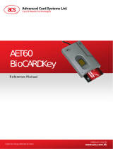
3.0. System Block Diagram
The USB Hub Controller is the communication interface between the PC and the MCU of the smart
card and flash memory via USB port connection. The 1-GB flash memory is available for the end-user
to use as storage. In Windows Explorer, the device is detected as a removable disk. The ACR101
(CCID) is powered from the USB port without other external power supply.
1-GB Flash Memory
USB
Interface
Comp
uter
USB 2.0
Hub
Controller
Smart Card
Smart Card
Interface Circuit
Figure 1: ACR1
01 System Block Diagram
Document Title Here
Document Title Here
Document Title Here
ACR101 PC/SC Memory Card Access
Version 1.0
Page 5 of 19
www.acs.com.hk

4.0. Power Supply
The ACR101 (CCID) requires a voltage of 5V DC, 100mA regulated power supply. It gets the power
supply from the PC.
4.1. Status LED
Bicolor LED on the front of the reader indicates the activation status of the smart card and flash
memory interface.
GREEN LED:
Flashing slowly (turns on 200ms for every 2 seconds)
Indicates smart card interface part is powered up and in the standby state. Either the smart
card has not been inserted or the smart card has not been powered up (if it is inserted).
Lighting up
Indicates power supply to the smart card is switched on, i.e., the smart card is activated.
RED LED:
Lighting up
Indicates a communication between ACR101 (CCID) and flash memory.
Document Title Here
Document Title Here
Document Title Here
ACR101 PC/SC Memory Card Access
Version 1.0
Page 6 of 19
www.acs.com.hk

5.0. Smart Card Interface
The interface between the ACR101 (CCID) and the inserted smart card follows the specifications of
ISO7816-3.
5.1. Smart Card Power Supply VCC (C1)
The current consumption of the inserted card must not be higher than 50mA.
5.2. Programming Voltage VPP (C6)
According to ISO 7816-3, the smart card contact C6 (VPP) supplies the programming voltage to the
smart card. Since all common smart cards in the market are EEPROM based and do not require the
provision of an external programming voltage, the contact C6 (VPP) has been implemented as a
normal control signal in the ACR101 (CCID). The electrical specifications of this contact are identical
to those of the signal RST (at contact C2).
5.3. Card Type Selection
The controlling PC has to select the card type always, through the proper command sent to the
ACR101 (CCID) prior to activating the inserted card. This includes both the memory cards and MCU-
based cards. For MCU-based cards the reader allows to select the preferred protocol, T=0 or T=1.
However, this selection is only accepted and carried out by the reader through the PPS when the card
inserted in the reader supports both protocol types. Whenever an MCU-based card supports only one
protocol type, T=0 or T=1, the reader automatically uses that protocol type, regardless of the protocol
type selected by the application.
5.4. Interface for Microcontroller-Based Cards
For microcontroller-based smart cards, only the contacts C1 (VCC), C2 (RST), C3 (CLK), C5 (GND)
and C7 (I/O) are used. A frequency of 4 MHz is applied to the CLK signal (C3).
5.5. Card Tearing Protection
The ACR101 (CCID) provides a mechanism to protect the inserted card when it is suddenly withdrawn
while it is powered up. The power supply to the card and the signal lines between the ACR101 (CCID)
and the card are immediately deactivated when the card is being removed. As a general rule,
however, to avoid any electrical damage, a card should only be removed from the reader while it
is powered down.
Note: The ACR101 (CCID) never switches on the power supply to the inserted card by itself.
This must be done by the controlling computer through the proper command sent to the reader.
Document Title Here
Document Title Here
Document Title Here
ACR101 PC/SC Memory Card Access
Version 1.0
Page 7 of 19
www.acs.com.hk

6.0. USB Interface
The ACR101 (CCID) is connected to a computer through a USB following the USB standard.
6.1. Communication Parameters
The ACR101 (CCID) is connected to a computer through USB as specified in the USB Specification.
The ACR101 (CCID) is working in high speed mode, i.e. 480 Mbps, for the flash memory.
Pin Signal Function
1
V
BUS
+5V power supply for the reader
2
D-
Differential signal transmits data between ACR101 (CCID) and PC.
3
D+
Differential signal transmits data between ACR101 (CCID) and PC.
4
GND
Reference voltage level for power supply
6.2. Endpoints
The ACR101 (CCID) uses the following endpoints to communicate with the host computer:
Control Endpoint 0 For setup and control purposes
Bulk OUT Endpoint 1 For the command to be sent from host to Mass Storage Interface
(data packet size is 64 bytes)
Bulk IN Endpoint 1 For response to be sent from Mass Storage Interface to host (data
packet size is 64 bytes)
Bulk OUT Endpoint 2 For command to be sent from host to CCID Interface (data packet
size is 16 bytes)
Bulk IN Endpoint 2 For response to be sent from CCID Interface to host (data packet
size is 16 bytes)
Document Title Here
Document Title Here
Document Title Here
ACR101 PC/SC Memory Card Access
Version 1.0
Page 8 of 19
www.acs.com.hk

7.0. Communication Protocol
ACR101 (CCID) interfaces with the host via USB connection. It is a compounded device consisting of
two interfaces: Chip Card Interface Device and Mass Storage.
The ACR101 (CCID) Smart Card Interface shares the same core as the smart card interface of the
ACR38 CCID. The Smart Card Interface will be identified as “ACR38-112c” once the reader FW is
obtained. (The command for this will be discussed later on). CCID covers all the protocols required for
operating smart cards and PIN.
The configurations and usage of USB endpoints on ACR101 (CCID) Smart Card Interface shall follow
CCID Section 3. An overview is summarized below:
1. Control Commands are sent on control pipe (default pipe). These include class-specific
requests and USB standard requests. Commands that are sent on the default pipe report
information back to the host on the default pipe.
2. CCID Events are sent on the interrupt pipe.
3. CCID Commands are sent on BULK-OUT endpoint. Each command sent to smart card reader
has an associated ending response. Some commands can also have intermediate responses.
4. CCID Responses are sent on BULK-IN endpoint. All commands sent to the smart card
reader have to be sent synchronously. (i.e. bMaxCCIDBusySlots is equal to 1)
The supported CCID features by ACR101 (CCID) smart card interface are indicated in its Class
Descriptor:
Offset Field Size Value Description
0
bLength
1
36h
Size of this descriptor, in
bytes.
1
bDescriptorType
1
21h
CCID Functional Descriptor
type.
2
bcdCCID
2
0100h
CCID Specification Release
Number in Binary-Coded
decimal.
4
bMaxSlotIndex
1
00h
One slot is available
5
bVoltageSupport
1
07h
The Smart card reader can
supply 1.8V, 3.0V and 5.0V
to its slot.
6
dwProtocols
4
00000003h
The Smart card reader
supports T=0 and T=1
Protocol
10
dwDefaultClock
4
00000FA0h
Default ICC clock frequency
is 4MHz
14
dwMaximumClock
4
00000FA0h
Maximum supported ICC
clock frequency is 4MHz
18
bNumClockSupported
1
00h
Does not support manual
setting of clock frequency
19
dwDataRate
4
00002A00h
Default ICC I/O data rate is
10752 bps
23
dwMaxDataRate
4
0001F808h
Maximum supported ICC I/O
data rate is 344 kbps
27
bNumDataRatesSupport
ed
1
00h
Does not support manual
setting of data rates
28
dwMaxIFSD
4
00000Feh
Maximum IFSD supported
by the smart card reader for
protocol T=1 is 254
Document Title Here
Document Title Here
Document Title Here
ACR101 PC/SC Memory Card Access
Version 1.0
Page 9 of 19
www.acs.com.hk

Document Title Here
Document Title Here
Document Title Here
ACR101 PC/SC Memory Card Access
Version 1.0
Page 10 of 19
www.acs.com.hk
Offset Field Size Value Description
32
dwSynchProtocols
4
00000000h
The Smart card reader does
not support synchronous
card
36
dwMechanical
4
00000000h
The Smart card reader does
not support special
mechanical characteristics
40
dwFeatures
4
00010030h
The Smart card reader
supports the following
features:
Automatic ICC clock
frequency change
according to
parameters
Automatic baud rate
change according to
frequency and FI,DI
parameters
TPDU level
exchange with the
smart card reader
44
dwMaxCCIDMessageLeng
th
4
0000010Fh
Maximum message length
accepted by the smart card
reader is 271 bytes
48
bClassGetResponse
1 00h
Insignificant for TPDU level
exchanges
49
bClassEnvelope
1 00h
Insignificant for TPDU level
exchanges
50
wLCDLayout
2 0000h No LCD
52
bPINSupport
1 00h No PIN Verification
53
bMaxCCIDBusySlots
1 01h
Only 1 slot can be
simultaneously busy
7.1. Command to the ACR101 (CCID)
In a normal operation, the ACR101 (CCID) acts as a slave device with regards to the communication
between a computer and the reader. The communication is carried out in the form of successive
command-response exchanges. The computer transmits a command to the reader and receives a
response from the reader after the command has been executed. A new command can be transmitted
to the ACR101 (CCID) only after the response to the previous command has been received.
There are two cases where the reader transmits data without having received a command from the
computer, namely, the Reset Message of the reader and the Card Status Message.
7.1.1. CCID Command Pipe Bulk-OUT Messages
The ACR101 (CCID) shall follow the CCID Bulk-OUT Messages as specified in CCID section 4. In
addition, this specification defines some extended commands for operating additional features. This
section lists the CCID Bulk-OUT Messages to be supported by ACR101 (CCID).
7.1.1.1. PC_to_RDR_IccPowerOn
Activate the card slot and return ATR from the card.

Offset Field Size Value Description
0
bMessageType
1
62h
1
dwLength
4
00000000h
Size of extra bytes of this message
2
bSlot
1
Identifies the slot number for this
command
5
bSeq
1
Sequence number for command
6
bPowerSelect
1
Voltage that is applied to the ICC
00h – Automatic Voltage Selection
01h – 5 volts
02h – 3 volts
7
abRFU
2 Reserved for future use
The response to this message is the RDR_to_PC_DataBlock message and the data returned is the
Answer To Reset (ATR) data.
7.1.1.2. PC_to_RDR_IccPowerOff
Deactivate the card slot.
Offset Field Size Value Description
0
bMessageType
1
63h
1
dwLength
4
00000000h
Size of extra bytes of this message
5
bSlot
1
Identifies the slot number for this
command
6
bSeq
1 Sequence number for command
7
abRFU
3 Reserved for future use
The response to this message is the RDR_to_PC_SlotStatus message.
7.1.1.3. PC_to_RDR_GetSlotStatus
Get current status of the slot.
Offset Field Size Value Description
0
bMessageType
1
65h
1
dwLength
4
00000000h
Size of extra bytes of this
message
5
bSlot
1
Identifies the slot number for this
command
6
bSeq
1
Sequence number for command
7
abRFU
3
Reserved for future use
The response to this message is the RDR_to_PC_SlotStatus message.
Document Title Here
Document Title Here
Document Title Here
ACR101 PC/SC Memory Card Access
Version 1.0
Page 11 of 19
www.acs.com.hk

7.1.1.4. PC_to_RDR_XfrBlock
Transfer data block to the ICC.
Offset Field Size Value Description
0
bMessageType
1
6Fh
1
dwLength
4
Size of abData field of this message
5
bSlot
1
Identifies the slot number for this
command
6
bSeq
1
Sequence number for command
7
bBWI
1
Used to extend the CCIDs Block
Waiting Timeout for this current
transfer. The CCID will timeout the
block after “this number multiplied by
the Block Waiting Time” has expired.
8
wLevelParameter
2
0000h
RFU (TPDU exchange level)
10
abData
Byte
array
Data block sent to the CCID. Data is
sent “as is” to the ICC (TPDU exchange
level)
The response to this message is the RDR_to_PC_DataBlock message.
7.1.1.5. PC_to_RDR_GetParameters
Get slot parameters.
Offset Field Size Value Description
0
bMessageType
1
6Ch
1
DwLength
4
00000000
h
Size of extra bytes of this message
5
BSlot
1
Identifies the slot number for this
command
6
BSeq
1 Sequence number for command
7
AbRFU
3 Reserved for future use
The response to this message is the RDR_to_PC_Parameters message.
7.1.1.6. PC_to_RDR_ResetParameters
Reset slot parameters to default value.
Offset Field Size Value Description
0
bMessageType
1
6Dh
1
DwLength
4
00000000h
Size of extra bytes of this message
5
BSlot
1
Identifies the slot number for this
command
6
BSeq
1
Sequence number for command
7
AbRFU
3
Reserved for future use
The response to this message is the RDR_to_PC_Parameters message.
Document Title Here
Document Title Here
Document Title Here
ACR101 PC/SC Memory Card Access
Version 1.0
Page 12 of 19
www.acs.com.hk

7.1.1.7. PC_to_RDR_SetParameters
Set slot parameters.
Offset
Field
Size Value Description
0
bMessageType
1
61h
1
dwLength
4 Size of extra bytes of this message
5
bSlot
1
Identifies the slot number for this
command
6
bSeq
1 Sequence number for command
7
bProtocolNum
1
Specifies what protocol data structure
follows.
00h = Structure for protocol T=0
01h = Structure for protocol T=1
The following values are reserved for
future use.
80h = Structure for 2-wire protocol
81h = Structure for 3-wire protocol
82h = Structure for I2C protocol
8
abRFU
2 Reserved for future use
10
abProtocolData
Structure
Byte
array
Protocol Data Structure
Protocol Data Structure for Protocol T=0 (dwLength=00000005h)
Offset Field Size Value Description
10
bmFindexDindex
1
B7-4 – FI – Index into the table 7 in
ISO/IEC 7816-3:1997 selecting a
clock rate conversion factor
B3-0 – DI - Index into the table 8 in
ISO/IEC 7816-3:1997 selecting a
baud rate conversion factor
11
bmTCCKST0
1
B0 – 0b, B7-2 – 000000b
B1 – Convention used (b1=0 for
direct, b1=1 for inverse) Note: The
CCID ignores this bit.
12
bGuardTimeT0
1
Extra Guardtime between two
characters. Add 0 to 254 etu to the
normal guardtime of 12 etu. FFh is
the same as 00h.
13
bWaitingIntegerT0
1 WI for T=0 used to define WWT
14
bClockStop
1
ICC Clock Stop Support
00h = Stopping the Clock is not
allowed
01h = Stop with Clock signal Low
02h = Stop with Clock signal High
03h = Stop with Clock either High or
Low
Document Title Here
Document Title Here
Document Title Here
ACR101 PC/SC Memory Card Access
Version 1.0
Page 13 of 19
www.acs.com.hk

Protocol Data Structure for Protocol T=1 (dwLength=00000007h)
Offset Field Size Value Description
10
bmFindexDindex
1
B7-4 – FI – Index into the table 7 in ISO/IEC
7816-3:1997 selecting a clock rate conversion
factor
B3-0 – DI - Index into the table 8 in
ISO/IEC 7816-3:1997 selecting a baud rate
conversion factor
11
BmTCCKST1
1
B7-2 – 000100b
B0 – Checksum type (b0=0 for LRC, b0=1 for
CRC)
B1 – Convention used (b1=0 for direct, b1=1
for inverse) Note: The CCID ignores this bit.
12
BGuardTimeT1
1
Extra Guardtime (0 to 254 etu between two
characters). If value is FFh, then guardtime is
reduced by 1 etu.
13
BwaitingIntege
rT1
1
B7-4 = BWI values 0-9 valid
B3-0 = CWI values 0-Fh valid
14
bClockStop
1
ICC Clock Stop Support
00h = Stopping the Clock is not allowed
01h = Stop with Clock signal Low
02h = Stop with Clock signal High
03h = Stop with Clock either High or Low
15
bIFSC
1 Size of negotiated IFSC
16
bNadValue
1
00h
Only support NAD = 00h
The response to this message is the RDR_to_PC_Parameters message.
7.1.2. CCID Bulk-IN Messages
The Bulk-IN messages are used in response to the Bulk-OUT messages. ACR101 (CCID) shall
follow the CCID Bulk-IN Messages as specified in section 4. This section lists the CCID Bulk-IN
Messages to be supported by ACR101 (CCID).
7.1.2.1. RDR_to_PC_DataBlock
This message is sent by the smart card reader in response to PC_to_RDR_IccPowerOn,
PC_to_RDR_XfrBlock and PC_to_RDR_Secure messages.
Offset Field Size Value Description
0
bMessageType
1
80h
Indicates that a data block is being sent from
the CCID
1
dwLength
4 Size of extra bytes of this message
5
bSlot
1
Same value as in Bulk-OUT message
6
bSeq
1
Same value as in Bulk-OUT message
7
bStatus
1
Slot status register as defined in CCID section
4.2.1
8
bError
1
Slot error register as defined in CCID section
4.2.1 and this specification section 5.2.8
9
bChainParameter
1
00h
RFU (TPDU exchange level)
10
abData
Byte
array
This field contains the data returned
by the CCID
Document Title Here
Document Title Here
Document Title Here
ACR101 PC/SC Memory Card Access
Version 1.0
Page 14 of 19
www.acs.com.hk

7.1.2.2. RDR_to_PC_SlotStatus
This message is sent by the smart card reader in response to PC_to_RDR_IccPowerOff,
PC_to_RDR_GetSlotStatus, PC_to_RDR_Abort messages and Class specific ABORT request.
Offset Field Size Value Description
0
bMessageType
1
81h
1
dwLength
4
00000000h
Size of extra bytes of this message
5
bSlot
1
Same value as in Bulk-OUT message
6
bSeq
1
Same value as in Bulk-OUT message
7
bStatus
1
Slot status register as defined in CCID
section 4.2.1
8
bError
1
Slot error register as defined in CCID
section 4.2.1 and this specification
section 5.2.8
9
bClockStatus
1
value =
00h Clock running
01h Clock stopped in state L
02h Clock stopped in state H
03h Clock stopped in an unknown
state
All other values are RFU.
Document Title Here
Document Title Here
Document Title Here
ACR101 PC/SC Memory Card Access
Version 1.0
Page 15 of 19
www.acs.com.hk

7.1.2.3. RDR_to_PC_Parameters
This message is sent by the smart card reader in response to PC_to_RDR_GetParameters,
PC_to_RDR_ResetParameters and PC_to_RDR_SetParameters messages.
Offset Field Size Value Description
0
bMessageType
1
82h
1
dwLength
4
Size of extra bytes of this message
5
bSlot
1
Same value as in Bulk-OUT message
6
bSeq
1
Same value as in Bulk-OUT message
7
bStatus
1
Slot status register as defined in CCID
section 4.2.1
8
bError
1
Slot error register as defined in CCID
section 4.2.1 and this specification
section 5.2.8
9
bProtocolNum
1
Specifies what protocol data structure
follows.
00h = Structure for protocol T=0
01h = Structure for protocol T=1
The following values are reserved for
future use.
80h = Structure for 2-wire protocol
81h = Structure for 3-wire protocol
82h = Structure for I2C protocol
10
abProtocolData
Structure
Byte
array
Protocol Data Structure as summarized
in section 5.2.3.
7.1.3. Commands Accessed via PC_to_RDR_XfrBlock
7.1.3.1. GET_READER_INFORMATION
This command returns relevant information about the particular smart card reader model and the
current operating status such as the firmware revision number, the maximum data length of a
command and response, the supported card types, and whether a card is inserted and powered up or
not.
Note: This command can only be used after the logical smart card reader communication has been
established using the SCardConnect() API. For details of SCardConnect() API, please refer to PC/SC
specification.
Pseudo-APDU
CLA INS P1 P2 Lc
FF
H
09
H
00
H
00
H
10
H
Command format (abData field in the PC_to_RDR_XfrBlock)
FIRMWARE MAX_C MAX_R C_TYPE C_SEL C_STAT
Response data format (abData field in the RDR_to_PC_DataBlock)
Document Title Here
Document Title Here
Document Title Here
ACR101 PC/SC Memory Card Access
Version 1.0
Page 16 of 19
www.acs.com.hk

FIRMWARE 10 bytes data for firmware version
MAX_C The maximum number of command data bytes.
MAX_R The maximum number of data bytes that can be requested to be transmitted in a
response.
C_TYPE The card types supported by the smart card reader. This data field is a bitmap with
each bit representing a particular card type. A bit set to '1' means the corresponding
card type is supported by the reader and can be selected with the
SELECT_CARD_TYPE command. The bit assignment is as follows:
Byte 1 2
card type
F E D C B A 9 8 7 6 5 4 3 2 1 0
See Appendix A.1 for the correspondence between these bits and the respective card
types.
C_SEL The currently selected card type. A value of 00
H
means that no card type has been
selected.
C_STAT Indicates whether a card is physically inserted in the reader and whether the card is
powered up:
00
H
: no card inserted
01
H
: card inserted, not powered up
03
H
: card powered up
7.2. Mass Storage
Mass Storage Device Class specifies all the protocols required for data transaction between Host
(computer) and storage devices. The configurations and usage of USB endpoints on ACR101 (CCID)
shall follow Mass Storage Class Bulk-Only Transport in Section 3 (Protocol Code) of the USB Mass
Storage Device Specification. This document is available at: www.usb.org.
An overview of this specification is summarized below:
1. Control Commands are sent on control pipe (default pipe). It is shared with the CCID
interface.
2. Data-Out Command Protocol uses the BULK-OUT endpoint to transfer data from the host to
the device.
3. Data-In Command Protocol uses the BULK-IN endpoint to transfer data from the device or to
return status about the device.
Document Title Here
Document Title Here
Document Title Here
ACR101 PC/SC Memory Card Access
Version 1.0
Page 17 of 19
www.acs.com.hk

Appendix A. Supported Card Types
The following table is a list of the card types returned by GET_READER_INFORMATION corresponding
with the respective card type code:
Card type code Card Type
00
H
Auto-select T=0 or T=1 communication protocol
01
H
I2C memory card (1k, 2k, 4k, 8k and 16k bits)
02
H
I2C memory card (32k, 64k, 128k, 256k, 512k
and 1024k bits)
03
H
Atmel AT88SC153 secure memory card
04
H
Atmel AT88SC1608 secure memory card
05
H
Infineon SLE4418 and SLE4428
06
H
Infineon SLE4432 and SLE4442
07
H
Infineon SLE4406, SLE4436 and SLE5536
08
H
Infineon SLE4404
09
H
Atmel AT88SC101, AT88SC102 and AT88SC1003
0C
H
MCU-based cards with T=0 communication
protocol
0D
H
MCU-based cards with T=1 communication
protocol
Document Title Here
Document Title Here
Document Title Here
ACR101 PC/SC Memory Card Access
Version 1.0
Page 18 of 19
www.acs.com.hk

Document Title Here
Document Title Here
Document Title Here
ACR101 PC/SC Memory Card Access
Version 1.0
Page 19 of 19
www.acs.com.hk
Appendix B. Response Status Codes
The following table is a list of the error codes that may be returned by the ACR38:
Error Code Status
FF
H
SLOTERROR_CMD_ABORTED
FE
H
SLOTERROR_ICC_MUTE
FD
H
SLOTERROR_XFR_PARITY_ERROR
FC
H
SLOTERROR_XFR_OVERRUN
FB
H
SLOTERROR_HW_ERROR
F8
H
SLOTERROR_BAD_ATR_TS
F7
H
SLOTERROR_BAD_ATR_TCK
F6
H
SLOTERROR_ICC_PROTOCOL_NOT_SUPPORTED
F5
H
SLOTERROR_ICC_CLASS_NOT_SUPPORTED
F4
H
SLOTERROR_PROCEDURE_BYTE_CONFLICE
F3
H
SLOTERROR_DEACTIVATED_PROTOCOL
F2
H
SLOTERROR_BUSY_WITH_AUTO_SEQUENCE
E0
H
SLOTERROR_CMD_SLOT_BUSY
/