
Subject to change without prior notice [email protected]k
www.acs.com.hk
Communication Protocol V1.03
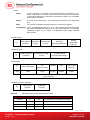
ACR122L
Serial NFC Reader
with LCD

ACR122L – Communication Protocol [email protected]
Version 1.03
www.acs.com.hk
Page 2 of 57
Table of Contents
1.0. Introduction ............................................................................................................... 4
2.0. Features ..................................................................................................................... 5
2.1. Serial Interface ....................................................................................................................... 5
2.2. LCD ........................................................................................................................................ 5
2.3. LEDs ...................................................................................................................................... 6
2.4. Buzzer .................................................................................................................................... 6
2.5. SAM Interface ........................................................................................................................ 6
2.6. Built-in Antenna ..................................................................................................................... 6
3.0. Communication between the host and contactless interface, SAM and
peripherals ............................................................................................................................. 7
4.0. Serial Interface (CCID-like Frame Format) .............................................................. 8
4.1. Protocol Flow Examples ........................................................................................................ 9
5.0. SAM Interface .......................................................................................................... 11
5.1. Activating the SAM Interface ............................................................................................... 11
5.2. Deactivating the SAM Interface ........................................................................................... 12
5.3. Exchanging data through the SAM Interface ....................................................................... 14
6.0. Pseudo-APDUs for contactless interface and peripherals control .................... 17
6.1. Direct Transmit .................................................................................................................... 17
6.2. Change Communication Speed ........................................................................................... 20
6.3. Get firmware version ............................................................................................................ 24
6.4. LCD Display (ASCII Mode) .................................................................................................. 25
6.5. LCD Display (GB Mode) ...................................................................................................... 28
6.6. LCD Display (Graphic Mode) ............................................................................................... 29
6.7. Scroll Current LCD Display .................................................................................................. 30
6.8. Pause LCD Scrolling ............................................................................................................ 31
6.9. Stop LCD Scrolling .............................................................................................................. 32
6.10. Clear LCD ............................................................................................................................ 32
6.11. LCD Backlight Control ......................................................................................................... 32
6.12. LCD Contrast Control .......................................................................................................... 33
6.13. LED Enable/Disable ............................................................................................................. 34
6.14. LED Control ......................................................................................................................... 34
6.15. LED and Buzzer Control ...................................................................................................... 35
6.16. Buzzer Control ..................................................................................................................... 41
6.17. Basic program flow for ISO 14443-4 Type A and B tags ..................................................... 41
6.18. Basic program flow for Mifare applications .......................................................................... 43
6.18.1. Handling the value blocks of Mifare 1K/4K tag ........................................................... 45
6.18.2. Accessing Mifare Ultralight tags .................................................................................. 47
6.18.3. Accessing Mifare Ultralight C tags .............................................................................. 49
6.19. Basic program flow for FeliCa applications ......................................................................... 53
6.20. Basic program flow for NFC Forum Type 1 tag applications ............................................... 54
Appendix A. ACR122 Error Codes .................................................................................. 56
List of Figures
Figure 1 : Communication Flowchart of ACR122L ................................................................................. 7
Figure 2 : Character Set A .................................................................................................................... 26
Figure 3 : Character Set B .................................................................................................................... 27
Figure 4 : Character Set C ................................................................................................................... 27
Figure 5 : LCD Display Position ........................................................................................................... 29

ACR122L – Communication Protocol [email protected]
Version 1.03
www.acs.com.hk
Page 3 of 57
List of Tables
Table 1 : PIN Configuration .................................................................................................................... 5
Table 2 : DDRAM Address for Font Sets 1 and 2 ................................................................................ 25
Table 3 : DDRAM Address for Font Set 3 ............................................................................................ 26
Table 4 : LCD Character Position Representation ............................................................................... 28
Table 5 : Scrolling Period ...................................................................................................................... 31
Table 6 : Scrolling Direction .................................................................................................................. 31
Table 7 : Mifare Ultralight Memory Map ............................................................................................... 49
Table 8 : Mifare Ultralight C Memory Map ............................................................................................ 53

ACR122L – Communication Protocol [email protected]
Version 1.03
www.acs.com.hk
Page 4 of 57
1.0. Introduction
The ACR122L serial protocol defines the interface between the PC and reader, as well as the
communication channel between the PC and the supported contactless tags/cards – ISO 14443-4
Type A and B, Mifare, ISO 18092 (NFC), and FeliCa. The major applications supported are the
following:
• Access Control, Identification: Reading the serial numbers of all cards in the field.
• Data Storage: Performing encrypted read-and-write operations.
• Ticketing: Performing read, write, increment and decrement operations in an encrypted
environment.
• Multi-applications: Performing read, write, increment and decrement operations on various
sectors of the card.

ACR122L – Communication Protocol [email protected]
Version 1.03
www.acs.com.hk
Page 5 of 57
2.0. Features
• Serial RS-232 Interface: Baud Rate = 115200 bps, 8-N-1
• 7 V DC adaptor for power supply
• CCID-like frame format (Binary format)
• Smart Card Reader:
o Read/Write speed of up to 424 kbps
o Built-in antenna for contactless tag access, with card reading distance of up to 50 mm
(depending on tag type)
o Support for ISO 14443 Part 4 Type A and B cards, Mifare, FeliCa and all four types of
NFC (ISO/IEC 18092) tags
o Built-in anti-collision feature (only one tag is accessed at any time)
o Three ISO 7816 compliant SAM slots
• Built-in Peripherals:
o Two-line graphic LCD with interactive operability (i.e. scroll up and down, left and right,
etc.) and multi-language support (i.e. Chinese, English, Japanese and several European
languages)
o Four user-controllable LEDs
o User-controllable buzzer
• Compliant with the following standards:
o ISO 14443
o CE
o FCC
o VCCI
o RoHS
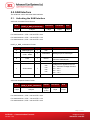
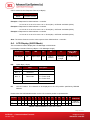
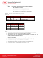
2.1. Serial Interface
The ACR122L is connected to a Host through the RS232C Serial Interface at 115200 bps, 8-N-1
Table 1: PIN Configuration
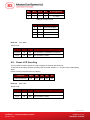
2.2. LCD
A user-controllable LCD is provided.
• 2 line x 16 character, 5 x 8 dot matrix, STN yellow-green LCD type
• Yellow-green backlight
• 6 O’clock view angle
Pin Signal Function
1 V
CC
+7 V power supply for the reader (max. 350 mA; normal 200 mA)
2 TXD
The signal from the reader to the host.
3 RXD
The signal from the host to the reader.
4 GND
Reference voltage level for power supply

ACR122L – Communication Protocol [email protected]
Version 1.03
www.acs.com.hk
Page 6 of 57
2.3. LEDs
Four user-controllable single color LEDs are provided.
• Control can be selected by firmware or by user.
• From left to right, the colors of the LEDs are green, blue, orange and red.
2.4. Buzzer
A user-controllable monotone buzzer with a default state of OFF is provided.
2.5. SAM Interface
Three SAM sockets, supporting ISO 7816-1/2/3 T=0 cards, are provided.
2.6. Built-in Antenna
A 3-turn symmetric loop antenna, center-tapped, is provided.
• Estimated size is 46 mm x 64 mm.
• Loop inductance is approximately 1.6 μH to 2.5 μH.
• Operating distance for different tags, is approximately up to 50 mm (depends on the tag).
• Only one tag can be accessed at any one time.

ACR122L – Communication Protocol [email protected]
Version 1.03
www.acs.com.hk
Page 7 of 57
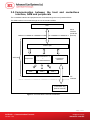
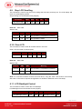
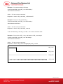
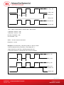
3.0. Communication between the host and contactless
interface, SAM and peripherals
The contactless interface and peripherals are accessed through the use of pseudo-APDUs.
The SAM interface is accessed through the use of standard APDUs.
Figure 1: Communication Flowchart of ACR122L
Serial
Interface
(CCID-like
protocol)
ISO 7816 Parts 1-3
+
T=0 SAM Interfaces
Contactless
Interface
SAM 1
Contactless Tag
(Built-in Antenna)
Host
ACR122L
PCSC Layer
Peripherals
SAM 3 SAM 2
RF
Interface

ACR122L – Communication Protocol [email protected]
Version 1.03
www.acs.com.hk
Page 8 of 57
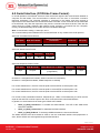
4.0. Serial Interface (CCID-like Frame Format)
In normal operation, the ACR122L acts as a slave device with regard to the communication between a
computer and the reader. The communication is carried out in the form of successive command-
response exchanges. The computer transmits a command to the reader, and then receives a
response from the reader after the command has been executed. A new command can be transmitted
to the ACR122L only after the response to the previous command has been received. There are two
cases where the reader transmits data without having received a command from the computer,
namely, the Reset Message of the reader and the Card Status Message.
Note: Communication setting: 115200 bps, 8-N-1.
The communication protocol between the host and ACR122L is very similar to the CCID protocol.
ACR122L Command Frame Format
STX (02h) Bulk-OUT Header
APDU Command or
Parameters
Checksum ETX (03h)
1 Byte 10 Bytes M Bytes (If applicable) 1 Byte 1 Byte
ACR122L Status Frame Format
STX (02h) Status Checksum ETX (03h)
1 Byte 1 Byte 1 Byte 1 Byte
ACR122L Response Frame Format
STX (02h) Bulk-IN Header APDU Response or abData Checksum ETX (03h)
1 Byte 10 Bytes
N Bytes
(If applicable)
1 Byte 1 Byte
Checksum = XOR {Bulk-OUT Header, APDU Command or Parameters}
Checksum = XOR {Bulk-IN Header, APDU Response or abData}
For control SAM Socket 1, the STX must be equal to 02h and ETX must be equal to 03h.
For control SAM Socket 2, the STX must be equal to 12h and ETX must be equal to 13h.
For control SAM Socket 3, the STX must be equal to 22h and ETX must be equal to 23h.
For control access Contactless interface, Peripherals (i.e. LEDs, LCD and Buzzer), the STX must be
equal to 02h and ETX must be equal to 03h, which is the same with control SAM Socket1.
In general, we would make use of three types of Bulk-OUT Header:
• HOST_to_RDR_IccPowerOn: To activate the SAM interface. The ATR of the SAM will be
returned if available.
• HOST_to_RDR_IccPowerOff: To deactivate the SAM interface.
• HOST_to_RDR_XfrBlock: To exchange APDUs between the host and ACR122L.
The SAM1 interface must be activated in order to use the contactless interface and peripherals. In
short, all the APDUs are exchanged through the SAM interface.

ACR122L – Communication Protocol [email protected]
Version 1.03
www.acs.com.hk
Page 9 of 57
Similarly, two types of Bulk-IN Header are used:
• RDR_to_HOST_DataBlock: In response to the HOST_to_RDR_IccPowerOn and
HOST_to_RDR_XfrBlock Frames.
• RDR_to_HOST_SlotStatus: In response to the HOST_to_RDR_IccPowerOff Frame.
RDR = ACR122L; HOST = Host Controller.
HOST_to_RDR = Host Controller -> ACR122L
RDR_to_HOST = ACR122L -> Host Controller
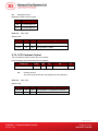
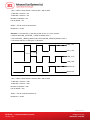
4.1. Protocol Flow Examples
(Use SAM Interface 1 as Example)
A. Activate a SAM.
HOST RDR
1. HOST sends a frame.
02 62 00 00 00 00 00 01 01 00 00 [Checksum] 03
2. RDR sends back a
positive status frame
immediately.
02 00 00 03 (positive status frame)
.. After some processing delay...
3. RDR sends back the
response of the
command.
02 80 0D 00 00 00 00 01 00 00 00 3B 2A 00 80 65
24 B0 00 02 00 82 90 00 [Checksum] 03
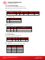
B. Activate a SAM (Incorrect Checksum, HOST)
HOST RDR
1. HOST sends a
corrupted frame.
02 62 00 00 00 00 00 01 01 00 00 [Incorrect
Checksum] 03
2. RDR sends back a
negative status frame
immediately.
02 FF FF 03 (negative status frame)
3. HOST sends the frame
again.
02 62 00 00 00 00 00 01 01 00 00 [Checksum] 03
4. RDR sends back a
positive status frame
immediately.
02 00 00 03 (positive status frame)
.. After some processing delay..
5. RDR sends back the
response of the
command.
02 80 0D 00 00 00 00 01 00 00 00 3B 2A 00 80 65
24 B0 00 02 00 82 90 00 [Checksum] 03

ACR122L – Communication Protocol [email protected]
Version 1.03
www.acs.com.hk
Page 10 of 57
C. Activate a SAM (Incorrect Checksum, RDR).
HOST RDR
1. HOST sends a frame.
02 62 00 00 00 00 00 01 01 00 00 [Checksum] 03
2. RDR sends back a
positive status frame
immediately.
02 00 00 03 (positive status frame)
.. After some processing delay...
3. RDR sends back the
response (corrupted) of
the command.
4. HOST sends a NAK
frame to get the
response again.
5. RDR sends back the
response of the
command.
02 80 0D 00 00 00 00 01 00 00 00 3B 2A 00 80 65
24 B0 00 02 00 82 90 00 [Incorrect Checksum] 03
02 00 00 00 00 00 00 00 00 00 00 00 03 (NAK)
02 80 0D 00 00 00 00 01 00 00 00 3B 2A 00 80 65
24 B0 00 02 00 82 90 00 [Checksum] 03
Note: If the frame sent by the HOST is correctly received by the RDR, a positive status frame = {02
00 00 03} will be sent to the HOST immediately to inform the HOST the frame is correctly received.
The HOST has to wait for the response of the command. The RDR will not receive any more frames
while the command is being processed.
In case of errors, a negative status frame will be sent to the HOST to indicate the frame is either
corrupted or incorrectly formatted.
CheckSum Error Frame = {02 FF FF 03}
Length Error Frame = {02 FE FE 03}. The length “dDwLength” is greater than 0105h bytes.
ETX Error Frame = {02 FD FD 03}. The last byte is not equal to ETX “03h”.
TimeOut Error Frame = {02 FC FC 03}. Not Complete Package Received.
The NAK Frame is only used by the HOST to get the last response.
{02 00 00 00 00 00 00 00 00 00 00 00 03} // 11 zeros

ACR122L – Communication Protocol [email protected]
Version 1.03
www.acs.com.hk
Page 11 of 57
5.0. SAM Interface
The ACR122L comes with three SAM interfaces.
5.1. Activating the SAM Interface
ACR122L Command Frame Format
STX
Bulk-OUT Header
(HOST_to_RDR_IccPowerOn)
Parameters Checksum ETX
1 Byte 10 Bytes 0 Byte 1 Byte 1 Byte
For SAM Interface 1, STX = 02h and ETX = 03h
For SAM Interface 2, STX = 12h and ETX = 13h
For SAM Interface 3, STX = 22h and ETX = 23h
HOST_to_RDR_IccPowerOn Format
Offset Field Size Value Description
0
bMessageType
1 62h
1
dDwLength
<LSB .. MSB>
4 00000000h Message-specific data length.
5
bSlot
1 00-FFh
Identifies the slot number for this
command. Default=00h.
6
bSeq
1 00-FFh Sequence number for command.
7
bPowerSelect
1
00h
01h
02h
03h
Voltage that is applied to the ICC:
00h – Automatic Voltage Selection
01h – 5.0 V
02h – 3.0 V
03h – 1.8 V
8
abRFU
2 Reserved for Future Use
ACR122L Response Frame Format
STX
Bulk-IN Header
(RDR_to_HOST_DataBlock)
abData Checksum ETX
1 Byte 10 Bytes
N Bytes
(ATR)
1 Byte 1 Byte
For SAM Interface 1, STX = 02h and ETX = 03h
For SAM Interface 2, STX = 12h and ETX = 13h
For SAM Interface 3, STX = 22h and ETX = 23h

ACR122L – Communication Protocol [email protected]
Version 1.03
www.acs.com.hk
Page 12 of 57
RDR_to_HOST_DataBlock Format
Offset Field Size Value Description
0
bMessageType
1 80h
Indicates that a data block is
being sent from the ACR122L.
1
dwLength
<LSB .. MSB>
4 N Size of abData field (N Bytes).
5
bSlot
1 Same as Bulk-OUT
Identifies the slot number for
this command.
6
bSeq
1 Same as Bulk-OUT
Sequence number for
corresponding command.
7
bStatus
1
8
bError
1
9
bChainParameter
1
Example 1: To activate the SAM Interface 1 slot 0 (default), sequence number = 1, 5 V card.
HOST -> 02 62 00 00 00 00 00 01 01 00 00 [Checksum] 03
RDR -> 02 00 00 03
RDR -> 02 80 0D 00 00 00 00 01 00 00 00 3B 2A 00 80 65 24 B0 00 02 00 82 90 00 [Checksum]
03
The ATR = 3B 2A 00 80 65 24 B0 00 02 00 82; SW1 SW2 = 90 00
Example 2: To activate the SAM Interface 2 slot 0 (default), sequence number = 1, 5 V card.
HOST -> 12 62 00 00 00 00 00 01 01 00 00 [Checksum] 13
RDR -> 12 00 00 13
RDR -> 12 80 0D 00 00 00 00 01 00 00 00 3B 2A 00 80 65 24 B0 00 02 00 82 90 00 [Checksum]
13
The ATR = 3B 2A 00 80 65 24 B0 00 02 00 82; SW1 SW2 = 90 00
Example 3: To activate the SAM Interface 3 slot 0 (default), sequence number = 1, 5 V card.
HOST -> 22 62 00 00 00 00 00 01 01 00 00 [Checksum] 23
RDR -> 22 00 00 23
RDR -> 22 80 0D 00 00 00 00 01 00 00 00 3B 2A 00 80 65 24 B0 00 02 00 82 90 00 [Checksum]
23
The ATR = 3B 2A 00 80 65 24 B0 00 02 00 82; SW1 SW2 = 90 00
5.2. Deactivating the SAM Interface
ACR122L Command Frame Format
STX
Bulk-OUT Header
(HOST_to_RDR_IccPowerOff)
Parameters Checksum ETX
1 Byte 10 Bytes 0 Byte 1 Byte 1 Byte

ACR122L – Communication Protocol [email protected]
Version 1.03
www.acs.com.hk
Page 13 of 57
For SAM Interface 1, STX = 02h and ETX = 03h
For SAM Interface 2, STX = 12h and ETX = 13h
For SAM Interface 3, STX = 22h and ETX = 23h
HOST_to_RDR_IccPowerOff Format
Offset Field Size Value Description
0
bMessageType
1 63h
1
dDwLength
<LSB .. MSB>
4 00000000h Message-specific data length.
5
bSlot
1 00-FFh
Identifies the slot number for this
command. Default=00h.
6
bSeq
1 00-FFh Sequence number for command.
7
abRFU
3 Reserved for Future Use.
ACR122L Response Frame Format
STX
Bulk-IN Header
(RDR_to_HOST_SlotStatus)
abData Checksum ETX
1 Byte 10 Bytes 0 Byte 1 Byte 1 Byte
For SAM Interface 1, STX = 02h and ETX = 03h
For SAM Interface 2, STX = 12h and ETX = 13h
For SAM Interface 3, STX = 22h and ETX = 23h
RDR_to_HOST_DataBlock Format
Offset Field Size Value Description
0
bMessageType
1 81h
Indicates that a data block is being
sent from the ACR122L.
1
dwLength
<LSB .. MSB>
4 0 Size of abData field (0 Bytes).
5
bSlot
1 Same as Bulk-OUT
Identifies the slot number for this
command.
6
bSeq
1 Same as Bulk-OUT
Sequence number for
corresponding command.
7
bStatus
1
8
bError
1
9
bClockStatus
1

ACR122L – Communication Protocol [email protected]
Version 1.03
www.acs.com.hk
Page 14 of 57
Example 1: To deactivate the SAM Interface 1 slot 0 (default), sequence number = 2.
HOST -> 02 63 00 00 00 00 00 02 00 00 00 [Checksum] 03
RDR -> 02 00 00 03
RDR -> 02 81 00 00 00 00 00 02 00 00 00 [Checksum] 03
Example 2: To deactivate the SAM Interface 2 slot 0 (default), sequence number = 2.
HOST -> 12 63 00 00 00 00 00 02 00 00 00 [Checksum] 13
RDR -> 12 00 00 13
RDR -> 12 81 00 00 00 00 00 02 00 00 00 [Checksum] 13
Example 3: To deactivate the SAM Interface 3 slot 0 (default), sequence number = 2.
HOST -> 22 63 00 00 00 00 00 02 00 00 00 [Checksum] 23
RDR -> 22 00 00 23
RDR -> 22 81 00 00 00 00 00 02 00 00 00 [Checksum] 23
5.3. Exchanging data through the SAM Interface
ACR122L Command Frame Format
STX
Bulk-OUT Header
(HOST_to_RDR_XfrBlock)
Parameters Checksum ETX
1 Byte 10 Bytes M Byte 1 Byte 1 Byte
For SAM Interface 1, STX = 02h and ETX = 03h
For SAM Interface 2, STX = 12h and ETX = 13h
For SAM Interface 3, STX = 22h and ETX = 23h
HOST_to_RDR_XfrBlock Format
Offset Field Size Value Description
0
bMessageType
1 6Fh
1
dDwLength
<LSB .. MSB>
4 M Message-specific data length.
5
bSlot
1 00-FFh
Identifies the slot number for this command.
Default=00h.
6
bSeq
1 00-FFh Sequence number for command.
7
bBWI
1 00-FFh Used to extend the Block Waiting Timeout.
8
wLevelParameter
2 0000h

ACR122L – Communication Protocol [email protected]
Version 1.03
www.acs.com.hk
Page 15 of 57
ACR122L Response Frame Format
For SAM Interface 1, STX = 02h and ETX = 03
For SAM Interface 2, STX = 12h and ETX = 13h
For SAM Interface 3, STX = 22h and ETX = 23h
RDR_to_HOST_DataBlock Format
Offset Field Size Value Description
0
bMessageType
1 80h
Indicates that a data block is
being sent from the ACR122L.
1
dwLength
<LSB .. MSB>
4 N Size of abData field (N Bytes).
5
bSlot
1 Same as Bulk-OUT
Identifies the slot number for
this command.
6
bSeq
1 Same as Bulk-OUT
Sequence number for
corresponding command.
7
bStatus
1
8
bError
1
9
bChainParameter
1
Example 1: To send an APDU “80 84 00 00 08” to the SAM Interface 1 slot 0 (default), sequence
number = 3.
HOST -> 02 6F 05 00 00 00 00 03 00 00 00 80 84 00 00 08 [Checksum] 03
RDR -> 02 00 00 03
RDR -> 02 80 0A 00 00 00 00 03 00 00 00 E3 51 B0 FC 88 AA 2D 18 90 00 [Checksum] 03
Response = E3 51 B0 FC 88 AA 2D 18; SW1 SW2 = 90 00
Example 2: To send an APDU “80 84 00 00 08” to the SAM Interface 2 slot 0 (default), sequence
number = 3.
HOST -> 12 6F 05 00 00 00 00 03 00 00 00 80 84 00 00 08 [Checksum] 13
RDR -> 12 00 00 13
RDR -> 12 80 0A 00 00 00 00 03 00 00 00 E3 51 B0 FC 88 AA 2D 18 90 00 [Checksum] 13
Response = E3 51 B0 FC 88 AA 2D 18; SW1 SW2 = 90 00
STX
Bulk-IN Header
(RDR_to_HOST_DataBlock)
abData Checksum ETX
1 Byte 10 Bytes
N Bytes
(ATR)
1 Byte 1 Byte

ACR122L – Communication Protocol [email protected]
Version 1.03
www.acs.com.hk
Page 16 of 57
Example 3: To send an APDU “80 84 00 00 08” to the SAM Interface 3 slot 0 (default), sequence
number = 3.
HOST -> 22 6F 05 00 00 00 00 03 00 00 00 80 84 00 00 08 [Checksum] 23
RDR -> 22 00 00 23
RDR -> 22 80 0A 00 00 00 00 03 00 00 00 E3 51 B0 FC 88 AA 2D 18 90 00 [Checksum] 23
Response = E3 51 B0 FC 88 AA 2D 18; SW1 SW2 = 90 00

ACR122L – Communication Protocol [email protected]
Version 1.03
www.acs.com.hk
Page 17 of 57
6.0. Pseudo-APDUs for contactless interface and
peripherals control
ACR122L comes with two primitive commands for this purpose <Class FFh>.
Note: For all the pseudo-APDUs below (except sections 5.2 – Changing the communication speed
and 5.3 – Get firmware version), STX MUST BE EQUAL to 02h and ETX MUST BE EQUAL to 03h.
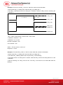
6.1. Direct Transmit
This command is used to send a pseudo-APDU (Tag Commands), and returns the length of the
Response Data.
Direct Transmit Command Format (Length of the Tag Command + 5 Bytes)
Command Class INS P1 P2 Lc Data In
Direct
Transmit
FFh 00h 00h 00h
Number of
bytes to send
Tag
Command
Data
Where:
Lc Number of bytes to send (1 Byte).
Maximum 255 bytes.
Data In Tag Command.
The data to be sent to the tag.
Direct Transmit Response Format (TAG Response + Data + 2 Bytes)
Item Command Data Meaning
1 D4 40 Tg [DataOut[]] Tag Exchange Data
2 D4 4A MaxTg BrTy [InitiatorData[]] Tag Polling
Where:
Tg A byte containing the logical number of the relevant target. This byte also
contains the More Information (MI) bit (bit 6). When the MI bit is set to 1, this
indicates that the host controller wants to send more data which is all the data
contained in the DataOUT[] array. This bit is only valid for a TPE target.
DataOut An array of raw data (from 0 up to 262 bytes) to be sent to the target by the
contactless chip.
MaxTg Maximum number of targets to be initialized by the contactless chip. The chip is
capable of handling 2 targets maximum at once, so this field should not exceed
02h.
Brty Baud rate and the modulation type to be used during the initialization.
00h: 106 kbps type A (ISO/IEC14443 Type A),
01h: 212 kbps (FeliCa polling),
02h: 424 kbps (FeliCa polling),
03h: 106 kbps type B (ISO/IEC 14443-3B),
04h: 106 kbps Innovision Jewel tag.
InitiatorData[] An array of data to be used during the initialization of the target(s). Depending on
the Baud Rate specified, the content of this field is different.

ACR122L – Communication Protocol [email protected]
Version 1.03
www.acs.com.hk
Page 18 of 57
106 kbps type A
The field is optional and is present only when the host controller wants to initialize a target with a
known UID.
In that case, InitiatorData[] contains the UID of the card (or part of it). The UID must include the
cascade tag CT if it is cascaded level 2 or 3.
Cascade Level 1
UID1 UID2 UID3 UID4
Cascade Level 2
UID1 UID2 UID3 UID4 UID5 UID6 UID7
Cascade Level 3
UID1 UID2 UID3 UID4 UID5 UID6 UID7 UID8 UID9 UID10
106 kbps type B
In this case, InitiatorData[] is formatted as following:
AFI (1byte) [Polling Method]
AFI The AFI (Application Family Identifier) parameter represents the type of
application targeted by the device IC and is used to preselect the PICCs before
the ATQB.
This field is mandatory.
Polling Method This field is optional. It indicates the approach to be used in the ISO/IEC 14443-
3B initialization:
If bit 0 = 1: Probabilistic approach (option 1) in the ISO/IEC 14443-3B
initialization,
If bit 0 = 0: Timeslot approach (option 2) in the ISO/IEC 14443-3B
initialization,
If this field is absent, the timeslot approach will be used.
212/424 kbps In that case, this field is mandatory and contains the complete pay load
information that should be used in the polling request command (5bypes, length
bytes is excluded)
106 kbps InnoVision Jewel tag. This field is not used.
Data Out Tag Response returned by the reader.
Direct Transmit Response Format
Response Data Out
Result
D5 41 Status [DataIn[]]
SW1 SW2
D5 4B NbTg [TargetData1[]] [TargetData2[]]

ACR122L – Communication Protocol [email protected]
Version 1.03
www.acs.com.hk
Page 19 of 57
Where:
Status A byte indicating if the process has been terminated successfully or not.
When in either DEP or ISO/IEC 14443-4 PCD mode, this byte also indicates
if NAD (Node Address) is used and if the transfer of data is not completed
with bit More Information.
DataIn An array of raw data (from 0 up to 262 bytes) received by the contactless
chip.
NbTg The number of initialized Targets (minimum 0, maximum 2 targets).
TargetDatai[] The “i” in TargetDatai[] refers to “1” or “2”. This contains the information about
the detected targets and depends on the baud rate selected. The following
information is given for one target, it is repeated for each target initialized
(NbTg times).
106 kbps Type A
Tg
SENS_RES10
(2 bytes)
SEL_RES
(1 byte)
NFCIDLength
(1 byte)
NFCID1[]
(NFCIDLength bytes)
[ATS[]]
(ATSLength
bytes11))
106 kbps Type B
Tg
ATQB Response
(12 bytes)
ATTRIB_RES Length
(1 byte)
ATTTRIB_RES[]
(ATTRIB_RES Length)
212/424 kbps
Tg
POL_RES length
01h
(response code)
NFCID2t
Pad
SYST_CODE
(optional)
1 byte 1 byte 1 byte 8 bytes 8 bytes 2 bytes
POL_RES
(18 or 20 bytes)
106 kbps Innovision Jewel tag
Tg
SENS_RES
(2 bytes)
JEWELID[]
(4 bytes)
Data Out SW1 SW2. Status Code returned by the reader.
Results SW1 SW2 Meaning
Success 90 00h The operation is completed successfully.
Error 63 00h The operation is failed.
Time Out Error 63 01h The TAG does not response.
Checksum Error 63 27h The checksum of the Response is wrong.

ACR122L – Communication Protocol [email protected]
Version 1.03
www.acs.com.hk
Page 20 of 57
Results SW1 SW2 Meaning
Parameter Error 63 7Fh The TAG Command is wrong.
6.2. Change Communication Speed
This command is used to change the baud rate.
Note: STX = 32h and ETX = 33h
Baud Rate Control Command Format (9 Bytes)
Command Class INS P1 P2 Lc
Baud Rate Control FFh 00h 44h New Baud Rate 00h
Where:
P2 New Baud Rate.
00h = Set the new baud rate to 9600 bps.
01h = Set the new baud rate to 115200 bps.
Data Out SW1 SW2.
Status Code
Results SW1 SW2 Meaning
Success 90 Current Baud Rate The operation is completed successfully.
Error 63 00h The operation is failed.
Where:
SW2 Current Baud Rate.
00h = The current baud rate is 9600 bps.
01h = The current baud rate is 115200 bps.
Note: After the communication speed is changed successfully, the program has to adjust its
communication speed to continue the rest of the data exchanges.
The initial communication speed is determined by the existence of R12 (0 ohm).
• With R12 = 115200 bps
• Without R12 = 9600 bps (default)
Example 1: To initialize a FeliCa Tag (Tag Polling).
Step 1. Issue a “Direct Transmit” APDU.
The APDU Command should be “FF 00 00 00 09 D4 4A 01 01 00 FF FF 01 00”
In which,
Direct Transmit APDU = “FF 00 00 00”
Length of the Tag Command = “09”
Page is loading ...
Page is loading ...
Page is loading ...
Page is loading ...
Page is loading ...
Page is loading ...
Page is loading ...
Page is loading ...
Page is loading ...
Page is loading ...
Page is loading ...
Page is loading ...
Page is loading ...
Page is loading ...
Page is loading ...
Page is loading ...
Page is loading ...
Page is loading ...
Page is loading ...
Page is loading ...
Page is loading ...
Page is loading ...
Page is loading ...
Page is loading ...
Page is loading ...
Page is loading ...
Page is loading ...
Page is loading ...
Page is loading ...
Page is loading ...
Page is loading ...
Page is loading ...
Page is loading ...
Page is loading ...
Page is loading ...
Page is loading ...
Page is loading ...
-
 1
1
-
 2
2
-
 3
3
-
 4
4
-
 5
5
-
 6
6
-
 7
7
-
 8
8
-
 9
9
-
 10
10
-
 11
11
-
 12
12
-
 13
13
-
 14
14
-
 15
15
-
 16
16
-
 17
17
-
 18
18
-
 19
19
-
 20
20
-
 21
21
-
 22
22
-
 23
23
-
 24
24
-
 25
25
-
 26
26
-
 27
27
-
 28
28
-
 29
29
-
 30
30
-
 31
31
-
 32
32
-
 33
33
-
 34
34
-
 35
35
-
 36
36
-
 37
37
-
 38
38
-
 39
39
-
 40
40
-
 41
41
-
 42
42
-
 43
43
-
 44
44
-
 45
45
-
 46
46
-
 47
47
-
 48
48
-
 49
49
-
 50
50
-
 51
51
-
 52
52
-
 53
53
-
 54
54
-
 55
55
-
 56
56
-
 57
57


Ask a question and I''ll find the answer in the document
Finding information in a document is now easier with AI
Related papers
-
 ACS ACR89U-A2 Reference guide
-
 ACS ACM1252U-Z6 User manual
-
 ACS ACR101 Reference guide
-
 ACS ACR3x mobile User manual
-
 ACS AET60 BioCARDKey Reference guide
-
 Advanced Card Systems ACR1255 User manual
-
 ACS ACR33U-A1 Smart Duo Reference guide
-
 Advanced Card Systems V5MACR1251U-A User manual
-
ACS ACR1581U-C1 User manual
-
 ACS ACR3901U-S1 Reference guide


Other documents
-
Elo 3203L 32" Interactive Display User guide
-
-
 Edwards Signaling 5532M-AQ Installation guide
-
System Sensor SENS-RDR User manual
-
Magtek IntelliStripe 65 Owner's manual
-
 Circle CIR315C User manual
-
CEM SAM 255 Installation guide
-
 Inside Secure Q45M2502G User manual
-
Escort Switch LRP2000 User manual
-
NXP PR5331C3HN User guide


