Page is loading ...

WinSystems, Inc.
715 Stadium Drive
Arlington, TX 76011
http://www.winsystems.com
WinSystems
®
EPX-C380-S
Intel
®
ATOM
TM
EPIC Single Board Computer
PRODUCT MANUAL

140206 PRODUCT MANUAL EPX-C380-S 2
Revision Date Code ECO Number
111219 Initial Release
120124 ECO 12-15
120307
120507
120703
120815
130304
130723
140206 ECO 14-06
MANUAL REVISION HISTORY
P/N 400-0380-002

140206 PRODUCT MANUAL EPX-C380-S 3
TABLE OF CONTENTS
BEFORE YOU BEGIN 6
Visual Index - Top View (Connectors) 7
Visual Index - Top View (Jumpers & LEDs) 8
Visual Index - Bottom View 9
Jumper Reference 10
INTRODUCTION 13
FEATURES 13
System 14
Memory 14
FUNCTIONALITY 15
I/O Port Map 15
Interrupt Map 17
PCI Devices and Functions 18
DOS Legacy Memory Map 18
Watchdog Timer 20
Real-Time Clock/Calendar 21
Status LED 21
CONNECTOR REFERENCE 22
POWER 22
J6 - Power and Reset 22
J8 - ATX Signals 22
J2 - Fan Power 22
JP2 - Power Supply Selection 23
BATTERY BACKUP 24
J4 - External Battery 24
PARALLEL PRINTER PORT 25
J20 - LPT 25
VIDEO 26
J1 - ANALOG VGA 26
J7 - LVDS 27
J5 - Backlight Power 27
JP1 - Panel Power 28
AUDIO 29
J10 - HD Audio 29
SP1 - Speaker 30
SERIAL 31
J18 - COM1, COM2, COM3, COM4 31
USB 33
J9, J11 - USB 33
SERIAL ATA 34
J13, J16 - SATA 34

140206 PRODUCT MANUAL EPX-C380-S 4
COMPACTFLASH 34
J501 - CompactFlash 34
1 MB SRAM 35
(Battery-Backed User Data Space) 35
OPTIONAL SSD 37
ETHERNET 38
J21 - Ethernet 38
J25, J26 - Ethernet LEDs 39
DIGITAL I/O 40
J23, J24 - Digital I/O 40
JP9 - Digital I/O Power 40
Register Denitions (WS16C48) 41
Register Details 41
PC/104 BUS 43
J12, J15 - PC/104 43
PC/104-Plus BUS 44
J14 - PC/104-Plus 44
MiniPCI EXPRESS 45
J502 - MiniPCIe 45
MiniPCIe LEDs 45
BIOS SUPPLEMENTAL 46
BIOS SETTINGS STORAGE OPTIONS 69
CABLES 71
SOFTWARE DRIVERS 72
SPECIFICATIONS 73
MECHANICAL DRAWING 74
APPENDIX - A 75
BEST PRACTICES 75
APPENDIX - B 79
POST CODES 79
WARRANTY INFORMATION 84

140206 PRODUCT MANUAL EPX-C380-S 5
This page has been left intentionally blank.

140206 PRODUCT MANUAL EPX-C380-S 6
BEFORE YOU BEGIN
WinSystems offers best practice recommendations for using and handling WinSystems embedded PCs. These methods
include valuable advice to provide an optimal user experience and to prevent damage to yourself and/or the product.
YOU MAY VOID YOUR WARRANTY AND/OR DAMAGE AN EMBEDDED PC BY FAILING TO COMPLY WITH THESE
BEST PRACTICES.
Reference Appendix - A for Best Practices.
For any questions you may have on WinSystems products, contact our Technical Support Group at (817) 274-7553, Monday
through Friday, between 8 AM and 5 PM Central Standard Time (CST).
Please review these guidelines carefully and follow them to ensure
you are successfully using your embedded PC.
This product ships with a heat sink. Product warranty is void if the
heat sink is removed from the product.

140206 PRODUCT MANUAL EPX-C380-S 7
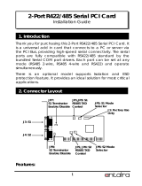
Visual Index - Top View (Connectors)
NOTE: The reference line to each component part has been drawn to Pin 1, and is also highlighted with a square, where applicable.
RESERVED - J3, J19, D12
J8
ATX Power
J6
Power
J24
Digital I/O
(Ports 3/4/5)
J23
Digital I/O
(Ports 0/1/2)
J20
LPT
J18
Serial I/O
(COM 1/2/3/4)
J11
USB
(0/1/2/3)
J9
USB
(4/5/6/7)
J5
Backlight Power
J1
Analog VGA
J15
PC/104
(C/D)
J12
PC/104
(A/B)
J10
HD Audio
J16
SATA1
J7
LVDS
J4
External Battery
J21
Ethernet
J13
SATA0
J14
PC/104-Plus
J22
Intruder Detection
J2
Fan

140206 PRODUCT MANUAL EPX-C380-S 8
Visual Index - Top View (Jumpers & LEDs)
NOTE: The reference line to each component part has been drawn to Pin 1, and is also highlighted with a square, where applicable.
RESERVED - J3, J19, D12
JP5
COM1
Termination
JP7
COM3
Termination
J26
Ethernet LEDs
(Port 1)
JP6
COM2
Termination
JP8
COM4
Termination
JP2
Power Supply
Selection
J25
Ethernet LEDs
(Port 2)
JP1
Panel Power
D14
Status LED
JP4
EEPROM Enable
JP3
CompactFlash
Master/Slave
JP9
Digial I/O Power

140206 PRODUCT MANUAL EPX-C380-S 9
D512
MiniPCIe WWAN
LED
D513
MiniPCIe WLAN
LED
D514
MiniPCIe WPAN
LED
Visual Index - Bottom View
NOTE: The reference line to each component part has been drawn to Pin 1, and is also highlighted with a square, where applicable.
RESERVED - J3, J19, D12
J502
MiniPCIe
J501
CompactFlash
J500
Memory
D515
Activity
Ethernet LED
(Port 2)
D516
Speed
Ethernet LED
(Port 2)
D517
Link
Ethernet LED
(Port 2)
D518
Activity
Ethernet LED
(Port 1)
D519
Speed
Ethernet LED
(Port 1)
D520
Link
Ethernet LED
(Port 1)
D511
IDE/SATA
Activity LED

140206 PRODUCT MANUAL EPX-C380-S 10
Jumper Reference
NOTE: Jumper Part# SAMTEC 2SN-BK-G is applicable to all jumpers. These are available in a ten piece kit from
WinSystems (Part# KIT-JMP-G-200).
JP5 - COM1, JP6 - COM2, JP7 - COM3, JP8 - COM4
JP5
2 4 6 8
□ □ □ □
□ □ □ □
1 3 5 7
JP6
2 4 6 8
□ □ □ □
□ □ □ □
1 3 5 7
JP7
2 4 6 8
□ □ □ □
□ □ □ □
1 3 5 7
JP8
2 4 6 8
□ □ □ □
□ □ □ □
1 3 5 7
JP4 - EEPROM
EEPROM Enable
CMOS Register Reset (only in G3 power mode) 1-2
SPI BIOS Write Protect 3-4
SPI BIOS Program Enable 5-6
CMOS EEPROM Enable (default) 7-8
CMOS EEPROM Disable 7 8
JP4
2 4 6 8
□ □ □ □
□ □ □ □
1 3 5 7
CompactFlash Master (default) 1-2
CompactFlash Slave 1 2
SSD Master 3-4
SSD Slave (default) 3 4
SSD Write Protect 5-6
SSD Program Enable (default) 5 6
Disable Ethernet Device 2 7-8
Enable Ethernet Device 2 (default) 7 8
JP3 - CompactFlash / Solid State Disk / Ethernet
JP3
2 4 6 8
□ □ □ □
□ □ □ □
1 3 5 7
RS-422 Termination and Biasing Resistors
TX (100): Places a 100Ω Resistor across the TX+/TX- pair 3-4
RX (100): Places a 100Ω Resistor across the RX+/RX- pair 7-8
TX(300):
Places a 100Ω Resistor from +5V to TX+ 1-2
Places a 100Ω Resistor between TX+ and TX- 3-4
Places a 100Ω Resistor from Ground to TX- 5-6
RS-485 Termination and Biasing Resistors
TX (100): Places a 100Ω Resistor across the TX/RX+/TX/RX- pair 3-4
TX/RX(300):
Places a 100Ω Resistor from +5V to TX/RX+ 1-2
Places a 100Ω Resistor between TX/RX+ and TX/RX- 3-4
Places a 100Ω Resistor from Ground to TX/RX- 5-6

140206 PRODUCT MANUAL EPX-C380-S 11
Jumper Reference (cont’d)
Avoid Simultaneous Jumpering of pins 1-2 and 2-3.
Misjumpering panel power causes damage to the
board and/or the Flat Panel.
Panel Power
5V
3.3V (default)
2-3
1-2
JP1 - Panel Power
AT Power 1-2, 3-4, 5-6, 7-8 (default)
ATX Power 1 2, 3 4, 5 6, 7 8
JP2 - Power Supply Selection
□ □
□ □
□ □
□ □
2
4
6
8
JP2
1
3
5
7
JP1
□ □ □
3 2 1
JP9 - Digital I/O VCC
+3.3V is provided at pin 49 of J23/J24 1-2
+5V is provided at pin 49 of J23/J24 2-3
No Power at Pin 49 of J23/J24 (default) OPEN
Avoid Simultaneous Jumpering of pins 1-2 and 2-3.
Misjumpering causes damage to the board.
JP9
□ □ □
3 2 1
5V
GND
+3V

140206 PRODUCT MANUAL EPX-C380-S 12
This page has been left intentionally blank.

140206 PRODUCT MANUAL EPX-C380-S 13
INTRODUCTION
This manual is intended to provide the necessary information regarding conguration and usage of the EPX-C380 single
board computer. WinSystems maintains a Technical Support Group to help answer questions not adequately addressed
in this manual. Contact Technical Support at (817) 274-7553, Monday through Friday, between 8 AM and 5 PM Central
Standard Time (CST).
FEATURES
CPU
• Intel
®
ATOM™ N450 (1.66 GHz) single core or D510 (1.66 GHz) dual core
Compatible Operating Systems
• Linux, Windows, DOS, and other x86 compatible OS
Memory
• Up to 2 GB of DDR2 SODIMM (Socketed)
BIOS
• Phoenix
Video
• Analog VGA or Flat Panel (simultaneous operation supported)
• Analog VGA resolution up to SXGA 1400x1050
• Flat Panel resolution up to 1366x768 or 1280x800
• Up to 18-bits/pixel color panel support
• LVDS supported
Ethernet
• 2 Intel
®
10/100/1000 Mbps controllers (one using PC82574 and one using ICH8M LAN)
*Model EPX-C380-S1-0 includes one Ethernet controller for ICH8M.
Storage
• 2 SATA (2.0) channels
• 1 MB soldered-on SRAM with battery backup
• Optional 512 MB - 2 GB soldered-on ash SSD
• CompactFlash Types I and II memory socket supported
Digital I/O
• 48 GPIO Bidirectional lines (WS16C48)
Serial I/O
• 4 serial ports (RS-232/422/485) (2-RS232/422/285) (2-RS-232 for EPX-C380-S1-0).
*RS-422/485 on COM3 and COM4 are not supported for model EPX-C380-S1-0.
Line Printer Port
• SPP/EPP supported
USB
• 8 USB 2.0 ports *USB(J11) is not applicable for model EPX-C380-S1-0.
Watchdog Timer
• Adjustable from 1 second to 255 minute reset
Audio
• HD Audio supported

140206 PRODUCT MANUAL EPX-C380-S 14
System
The EPX-C380 is an Intel
®
ATOM™ Single Board Computer (SBC) which uses either a 1.66 GHz single core Intel N450
or 1.66 GHz dual core D510 processor paired with the ICH8M controller hub. This is an EPIC-compatible unit and
incorporates two 10/100/1000 Mbps Ethernet controllers, two SATA channels, 48 lines of digital I/O, four serial RS-
232/422/485 ports, watchdog timer, and LPT. The SBC also supports HD audio, USB ports, and is equipped with a
CompactFlash socket and MiniPCIe card socket.
Memory
The EPX-C380 board supports up to 2 GB DDR2 SODIMM system memory via an on-board socket located at J500.
Power
• +5V required, 2.5A typical
Bus Expansion
• PC/104
• PC/104-Plus
• MiniPCIe *MiniPCIe not applicable for model EPX-C380-S1-0.
Industrial Operating Temperature
• -40°C to 85°C
Mechanical
• EPIC-compliant
• Dimensions: 4.50” x 6.50” (115 mm x 165 mm)
• Weight: 9.6 oz (272.2g)
Additional Features
• RoHS compliant
• Backlight power supported
• Custom splash screen on start-up
• Real-time clock/calendar

140206 PRODUCT MANUAL EPX-C380-S 15
FUNCTIONALITY
I/O Port Map
Following is a list of I/O ports used on the EPX-C380.
NOTE: The EPX-C380 uses a PnP BIOS resource allocation. Care must be taken to avoid contention with resources
allocated by the BIOS.
HEX Range Usage
0000h-001Fh DMA Controller 82C37
0020h-0021h Interrupt Controller PIC 8259
0024h-0025h Interrupt Controller
0028h-0029h Interrupt Controller
002Ch-002Dh Interrupt Controller
002Eh-002Fh Forward to Super IO
0030h-0031h Interrupt Controller
0034h-0035h Interrupt Controller
0038h-0039h Interrupt Controller
003Ch-003Dh Interrupt Controller
0040h-0043h Timer counter 8254
004Eh-004Fh Forward to Super IO
0050h-0053h Timer counter 8254
0060h Keyboard data port
0061h NMI controller
0062h 8051 download 4K address counter
0064h Keyboard status port
0066h 8051 download 8-bit data port
0070h-0077h RTC Controller
0080h-0091h DMA Controller
0092h Reset Generator
0093h-009Fh DMA Controller
00A0h-00A1h Interrupt Controller PIC 8259
00A4h-00A5h Interrupt Controller
00A8h-00A9h Interrupt Controller
0ACh-00ADh Interrupt Controller
00B0h-00B1h Interrupt Controller
00B2h-00B3h Power Management
00B4h-00B5h Interrupt Controller
00B8h-00B9h Interrupt Controller
00C0h-00DFh DMA Controller 82C37
00F0h FERR#/IGNNE/Interrupt Controller
0120h-012Fh Digital I/O (Default)
0140h-01FFh Reserved *
0170h-0177h IDE1 Controller
0180h-01FFh Reserved
0210h-0213h SRAM Control
0298h-029Bh Reserved for Super I/O Conguration
029Ch Interrupt Status Reigster
029Dh Status LED Register
029Eh-029Fh Watchdog Timer Control
02E8h-02EFh COM4 (Default)
02F8h-02FFh COM2 (Default)

140206 PRODUCT MANUAL EPX-C380-S 16
HEX Range Usage
0340h-03E7h Reserved *
0376h IDE1 Controller
0378h-037Bh LPT (Default)
03E8h-03EFh COM3 (Default)
03F0h-03F5h Reserved
03F6h IDE0 Controller
03F8h-03FFh COM1 (Default)
04D0h-4D1h Interrupt Controller
0564h-0568h Advanced Watchdog
0CF9h Reset Generator
This product utilizes a LPC to ISA Bridge to address the PC/104 bus. The majority of legacy PC/104 modules are I/O
mapped and function as expected. However, neither DMA nor memory mapped PC/104 modules are supported with this
product. The PC/104-Plus PCI signals are completely supported.
* The ICH8M limits the LPC (ISA) decode ranges to four windows, two of which can be adjusted in the BIOS. For
example, the 0300-033Fh range can be changed to 0600-06FFh so the full 256 bytes are available for PC/104 modules.
Resources addressed internally may still exist in these ranges so please check the I/O map for availability.
The advanced watchdog timer is the only on-board device affected by adjusting LPC (ISA) decode range. It will not be
available if the 0564-0568h decode range is disabled.
The default is for the PC/104 decode ranges are shown below. Please contact an Applications Engineer if you have
questions regarding the decode ranges.
0100-013Fh 64 Bytes (Fixed)
0200-02FFh 256 Bytes (Fixed)
0300-033Fh 64 Bytes (BIOS Selectable)
0500-05FFh 256 Bytes (BIOS Selectable)

140206 PRODUCT MANUAL EPX-C380-S 17
Interrupt Status Register - 29CH
Bit 7 Bit 6 Bit 5 Bit 4 Bit 3 Bit 2 Bit 1 Bit 0
N/A N/A N/A N/A COM4 COM3 COM2 COM1
Note: A 1 will be read for the device(s) with an interrupt pending.
Interrupt Map
WinSystems does not provide software support for implementing the Interrupt Status
Register to share interrupts. Some operating systems, such as Windows XP and Linux,
have support for sharing serial port interrupts and examples are available. The user will
need to implement the appropriate software to share interrupts for the other devices.
Hardware Interrupts (IRQs) are supported for both PC/104 (ISA), PCI and PCIe devices. The user must reserve IRQs in
the BIOS CMOS conguration for use by legacy devices. The PCIe/PnP BIOS will use unreserved IRQs when allocating
resources during the boot process. The table below lists IRQ resources as used by the EPX-C380.
IRQ0 18.2 Hz heartbeat
IRQ1 Keyboard
IRQ2 Chained to Slave controller (IRQ9)
IRQ3 COM2 *
IRQ4 COM1 *
IRQ5 COM3 *
IRQ6 COM4 *
IRQ7 LPT *
IRQ8 Real Time Clock
IRQ9 FREE **
IRQ10 Digital I/O
IRQ11 PCI Interrupts
IRQ12 Mouse
IRQ13 Floating point processor
IRQ14 IDE
IRQ15 IDE
*
These IRQ references are default settings that can be changed by the user in the CMOS Settings
utility. Reference the Super I/O Control section under Intel.
**
IRQ9 is commonly used by ACPI when enabled and may be unavailable (depending on operating
system) for other uses.
*** IRQ15 is currently unavailable under the Windows operating systems.
Some IRQs can be freed for other uses if the hardware features they are assigned to are not being
used. To free an interrupt, use the CMOS setup screens to disable any unused board features or their
IRQ assignments.

140206 PRODUCT MANUAL EPX-C380-S 18
PCI Devices and Functions
Bus:Device:Function Function Description
Bus 0:Device 0:Fun: 0 Processor Host Bridge/DMI Controller
Bus 0:Device 2:Fun: 0 Processor Host Bridge/Graphics Controller
Bus 0:Device 2:Fun: 0 Processor Host Bridge/Graphics Controller
Bus 0:Device 25:Fun: 0 Internal GbE Controller
Bus 0:Device 26:Fun: 1 USB UHCI Controller
Bus 0:Device 26:Fun: 7 USB UHCI Controller
Bus 0:Device 26:Fun: 7 USB EHCI Controller
Bus 0:Device 27:Fun: 0 Intel High Denition Audio Controller
Bus 0:Device 28:Fun: 0 PCI Express Port 1
Bus 0:Device 28:Fun: 1 PCI Express Port 2
Bus 0:Device 29:Fun: 0 USB UHCI Controller
Bus 0:Device 29:Fun: 1 USB UHCI Controller
Bus 0:Device 29:Fun: 2 USB UHCI Controller
Bus 0:Device 29:Fun: 7 USB EHCI Controller
Bus 0:Device 30:Fun: 0 PCI-to-PCI Bridge
Bus 0:Device 31:Fun: 0 LPC Bridge
Bus0:Device 31:Fun: 0 IDE Controller
Bus 0:Device 31:Fun: 2 SATA Controller
Bus 0:Device 31:Fun: 3 SMBus Controller
Bus 0:Device 31:Fun: 6 ICH8M Thermal Subsystem
Bus 1:Device 0:Fun: 0 External GbE Controller
Bus 2:Device 0:Fun: 0 PCI Express MiniCard
Bus 3:Devicex:Fun: 0 PCI 2.0
DOS Legacy Memory Map
HEX Range Usage
0000:0000-0009:FFFF Main Memory (DOS area)
000A:0000-000B:FFFF Legacy Video Area (SMM Memory)
000C:0000-000D:FFFF Expansion Area
000E:0000-000E:FFFF Extended System BIOS (Lower)
000F:0000-000F:FFFF System BIOS (Upper)
0010:0000-TOM (Top of Memory) Main Memory
FEC0:0000-FEC7:FFFF IO APIC
FED0:x000-FED0:x3FF High Precision Event Timers

140206 PRODUCT MANUAL EPX-C380-S 19
This page has been left intentionally blank.

140206 PRODUCT MANUAL EPX-C380-S 20
Watchdog Timer
The EPX-C380 features an advanced watchdog timer which can be used to guard against software lockups. Two
interfaces are provided to the watchdog timer. The Advanced interface is the most exible and recommended for new
designs. The other interface option is provided for software compatibility with older WinSystems single board computers.
Advanced
The watchdog timer can be enabled in the BIOS Settings by entering a value for Watchdog Timeout on the Intel → Super
I/O Control screen. Any non-zero value represents the number of minutes prior to reset during system boot. Once the
operating system is loaded, the watchdog can be disabled or recongured in the application software.
NOTE: It is recommended that a long timeout be used if the watchdog is enabled when trying to boot any operating
system.
The watchdog can be enabled, disabled or reset by writing the appropriate values to the conguration registers located
at I/O addresses 565h and 566h. The watchdog is enabled by writing a timeout value other than zero to the I/O address
566h and disabled by writing 00h to this I/O address. The watchdog timer is serviced by writing the desired timeout value
to I/O port 566h. If the watchdog has not been serviced within the allotted time, the circuit resets the CPU.
The timeout value can be set from 1 second to 255 minutes. If port 565h bit 7 equals 0, the timeout value written into I/O
address 566h is in minutes. The timeout value written to address 566h is in seconds if port 565 bit 7 equals 1.
Port Address Value Reset Interval
29EH
00h DISABLED
01h 3 SECONDS
03h 30 SECONDS
05h 300 SECONDS
29FH ANY RESET TIMER
Port Address Port Bit 7 Value Port Address Value Reset Interval
565H x 566H 00h DISABLED
565H 1 566H 03h 3 SECONDS
565H 1 566H 1Eh 30 SECONDS
565H 0 566H 04h 4 MINUTES
565H 0 566H 05h 5 MINUTES
Software watchdog timer PET = PORT 566H, write the timeout value.
Watchdog Timer Examples
Standard (requires changing the default I/O ranges within in the BIOS)
The watchdog can be enabled or disabled via software by writing an appropriate timeout value to I/O port 29EH. See the
chart provided below.
/