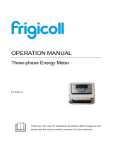
Socomec COUNTIS E2x Operating instructions
- Category
- Measuring, testing & control
- Type
- Operating instructions
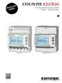
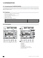
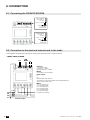
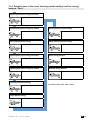
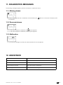
Socomec COUNTIS E2x is a three-phase energy meter that offers advanced metering and communication capabilities for various applications. It features direct connection for currents up to 80A, eliminating the need for current transformers. The backlit LCD display provides clear visibility of various electrical parameters, including voltage, current, power, energy consumption, and more. With its M-Bus communication interface, the COUNTIS E2x enables easy integration into smart metering systems, allowing for remote data collection and analysis.
Socomec COUNTIS E2x is a three-phase energy meter that offers advanced metering and communication capabilities for various applications. It features direct connection for currents up to 80A, eliminating the need for current transformers. The backlit LCD display provides clear visibility of various electrical parameters, including voltage, current, power, energy consumption, and more. With its M-Bus communication interface, the COUNTIS E2x enables easy integration into smart metering systems, allowing for remote data collection and analysis.


-
 1
1
-
 2
2
-
 3
3
-
 4
4
-
 5
5
-
 6
6
-
 7
7
-
 8
8
-
 9
9
-
 10
10
-
 11
11
-
 12
12
-
 13
13
-
 14
14
-
 15
15
-
 16
16
-
 17
17
-
 18
18
-
 19
19
-
 20
20
-
 21
21
-
 22
22
-
 23
23
-
 24
24
-
 25
25
-
 26
26
-
 27
27
-
 28
28
-
 29
29
-
 30
30
-
 31
31
-
 32
32


Socomec COUNTIS E2x Operating instructions
- Category
- Measuring, testing & control
- Type
- Operating instructions
Socomec COUNTIS E2x is a three-phase energy meter that offers advanced metering and communication capabilities for various applications. It features direct connection for currents up to 80A, eliminating the need for current transformers. The backlit LCD display provides clear visibility of various electrical parameters, including voltage, current, power, energy consumption, and more. With its M-Bus communication interface, the COUNTIS E2x enables easy integration into smart metering systems, allowing for remote data collection and analysis.
Ask a question and I''ll find the answer in the document
Finding information in a document is now easier with AI
Related papers
-
Socomec COUNTIS E1x Operating instructions
-
-
-
-
-
-
-
-
-
Other documents
-
Eltako DSZ15DE-3x80A User manual
-
Vemer Energy-400 PAR User manual
-
Elvaco ABB B21 Owner's manual
-
 Kaysun Wattmeter DTS343-3 User manual
-
Symphony E25 User manual
-
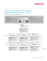
 Kamstrup OMNIPOWER® three-phase meter User guide
-
 Kamstrup OMNIPOWER® single-phase meter User guide
-
Lovato DME D305T2MID User manual
-
Eltako DSZ15DM-3x80A User manual
-


