Socomec COUNTIS E2x Operating instructions
- Category
- Measuring, testing & control
- Type
- Operating instructions
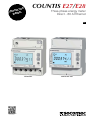
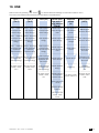
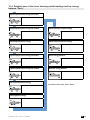
Socomec COUNTIS E2x is a three-phase energy meter designed for direct connection to currents up to 80 A. It provides accurate energy measurement, real-time readings, and various communication options for integration into smart grids and building management systems. With its advanced features, the COUNTIS E2x enables efficient energy monitoring, analysis, and optimization in commercial and industrial applications.
Socomec COUNTIS E2x is a three-phase energy meter designed for direct connection to currents up to 80 A. It provides accurate energy measurement, real-time readings, and various communication options for integration into smart grids and building management systems. With its advanced features, the COUNTIS E2x enables efficient energy monitoring, analysis, and optimization in commercial and industrial applications.


-
 1
1
-
 2
2
-
 3
3
-
 4
4
-
 5
5
-
 6
6
-
 7
7
-
 8
8
-
 9
9
-
 10
10
-
 11
11
-
 12
12
-
 13
13
-
 14
14
-
 15
15
-
 16
16
-
 17
17
-
 18
18
-
 19
19
-
 20
20
-
 21
21
-
 22
22
-
 23
23
-
 24
24
-
 25
25
-
 26
26
-
 27
27
-
 28
28
-
 29
29
-
 30
30


Socomec COUNTIS E2x Operating instructions
- Category
- Measuring, testing & control
- Type
- Operating instructions
Socomec COUNTIS E2x is a three-phase energy meter designed for direct connection to currents up to 80 A. It provides accurate energy measurement, real-time readings, and various communication options for integration into smart grids and building management systems. With its advanced features, the COUNTIS E2x enables efficient energy monitoring, analysis, and optimization in commercial and industrial applications.
Ask a question and I''ll find the answer in the document
Finding information in a document is now easier with AI
Related papers
-
Socomec COUNTIS E2x Operating instructions
-
-
-
-
-
-
-
-
-
Other documents
-
Philips 921501545502 Datasheet
-
Osram 4008321670953 Datasheet
-
DeLOCK 46193 Datasheet
-
Elvaco ABB B21 Owner's manual
-
Eltako DSZ15DE-3x80A User manual
-
Vemer Energy-400 PAR User manual
-
 Meters UK Ltd SmartLink EM737 CT User manual
-
 F F LE-01MR v2 Electric Energy Meter User manual
-
 Kamstrup OMNIPOWER® three-phase meter User guide
-
 Kamstrup OMNIPOWER® single-phase meter User guide


