
Operating Guide
VLT® AQUA Drive FC 202
110-800 kW, Enclosures D9h-D10h and E5h-E6h


Contents
1 Introduction 8
1.1 Purpose of this Operating Guide 8
1.2 Additional Resources 8
1.3 Manual Version 8
1.4 Approvals and Certifications 8
1.5 Disposal 9
2 Safety 10
2.1 Safety Symbols 10
2.2 Qualified Personnel 10
2.3 Safety Precautions 10
3 Product Overview 13
3.1 Intended Use 13
3.2 What is an Enclosed Drive? 13
3.3 Location of Options within an Enclosed Drive 16
3.4 Drive Identification 18
3.4.1 Identifying the Drive and Its Options 18
3.4.2 Enclosure Size Identification 20
3.4.3 Option Code Identification 20
3.5 Power Ratings and Dimensions for D9h–D10h and E5h–E6h Enclosures 24
3.6 Control Compartment and Local Control Panel 25
3.6.1 Control Compartment Overview 25
3.6.2 Control Compartment Door 26
3.6.3 Local Control Panel (LCP) 27
3.6.4 LCP Menu 29
4 Mechanical Installation 31
4.1 Items Supplied 31
4.2 Split Shipment 31
4.3 Tools Needed 32
4.4 Storage 32
4.5 Operating Environment 32
4.5.1 Operating Environment Overview 32
4.5.2 Gases within the Operating Environment 33
4.5.3 Dust within the Operating Environment 33
4.5.4 Potentially Explosive Atmospheres 33
4.6 Installation Requirements 34
4.7 Cooling Requirements 34
4.8 Airflow Rates 35
Contents
Operating Guide | VLT® AQUA Drive FC 202
AQ262141056213en-000101 / 130R0882 | 3Danfoss A/S © 2018.10

4.9 Lifting the Drive 36
4.10 Combining Multiple Cabinets from a Split Shipment 37
4.11 Installing the Enclosed Drive 39
4.11.1 Creating an Entry for Cables 39
4.11.2 Installing the Drive with Back-channel Cooling Option 40
4.11.3 Securing the Cabinet(s) to the Floor 40
5 Electrical Installation 42
5.1 Safety Instructions 42
5.2 EMC-compliant Installation 42
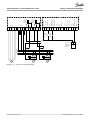
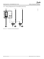
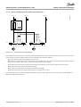
5.3 Wiring Schematic for D9h and D10h Enclosed Drives 46
5.4 Wiring Schematic for E5h and E6h Enclosed Drives 47
5.5 Wiring Diagram Cross-reference 48
5.6 Split Shipment Wiring Harnesses 49
5.6.1 Connecting Wiring Harnesses 49
5.6.2 D10h Wiring Harness 50
5.6.3 E5h Wiring Harness 54
5.6.4 E6h Wiring Harness 60
5.7 Control Compartment Wiring 66
5.7.1 Safety Precautions 66
5.7.2 Control Compartment Interior View 67
5.7.3 Control Terminals 68
5.7.4 Relay Terminals 69
5.7.5 Option Card Terminals 69
5.7.6 Overview of Options Wiring 72
5.8 Connecting Motor, Mains, and Ground Cables 79
5.8.1 Power Cabling and Grounding Considerations 79
5.8.2 Connecting to the Mains 81
5.8.3 Connecting the Drive Module to the Motor 85
5.8.4 Connecting the Sine-wave Filter to the Motor 87
5.8.5 Connecting the dU/dt Filter to the Motor 89
5.8.6 Connecting to Ground 91
5.9 Installing Upstream Fuses 92
5.9.1 Upstream Fuse Considerations 92
5.9.2 Recommended Fuse Ratings for IEC Installation 92
5.9.3 Recommended Fuse Ratings for UL Installation 93
5.10 Enabling Motor Operation 94
5.11 Selecting the Voltage/Current Input Signal 94
5.12 Setting Up RS485 Serial Communication 95
5.13 Configuring the Passive Harmonic Filter (PHF) 96
5.14 Configuring the dU/dt Filter 96
5.15 Configuring the Sine-wave Filter 97
Contents
Operating Guide | VLT® AQUA Drive FC 202
AQ262141056213en-000101 / 130R08824 | Danfoss A/S © 2018.10

5.16 MCCB Configuration 97
5.17 Safe Torque Off (STO) Wiring 98
6 Pre-start Check List 99
7 Commissioning 101
7.1 Applying Power to the Drive 101
7.2 Programming the Drive 101
7.2.1 Parameter Overview 101
7.2.2 Parameter Navigation 102
7.2.3 Programming Example for an Open-loop Application 102
7.2.4 Entering System Information 103
7.2.5 Configuring Automatic Energy Optimization 104
7.2.6 Configuring Automatic Motor Adaptation 105
7.3 Testing Before System Start-up 105
7.3.1 Testing Motor Rotation 105
7.3.2 Testing Encoder Rotation 106
7.4 Starting Up the Drive for the First Time 106
7.5 Parameter Settings 106
7.5.1 Parameter Setting Overview 106
7.5.2 Uploading and Downloading Parameter Settings 107
7.5.3 Restoring Factory Default Settings Using the Recommended Initialization 107
7.5.4 Restoring Factory Default Settings Using Manual Initialization 108
8 Wiring Configuration Examples 109
8.1 Application Examples 109
8.1.1 Wiring Configuration for Automatic Motor Adaptation (AMA) 109
8.1.2 Wiring Configuration for Automatic Motor Adaptation (AMA) without T27 110
8.1.3 Wiring Configuration: Speed 110
8.1.4 Wiring Configuration: Feedback 113
8.1.5 Wiring Configuration: Run/Stop 115
8.1.6 Wiring Configuration: Start/Stop 117
8.1.7 Wiring Configuration: External Alarm Reset 119
8.1.8 Wiring Configuration: RS485 120
8.1.9 Wiring Configuration: Motor Thermistor 120
8.1.10 Wiring for Regeneration 121
8.1.11 Wiring Configuration for a Relay Set-up with Smart Logic Control 122
8.1.12 Wiring Configuration for a Submersible Pump 122
8.1.13 Wiring Configuration for a Cascade Controller 125
8.1.14 Wiring Configuration for a Fixed Variable Speed Pump 127
8.1.15 Wiring Configuration for Lead Pump Alternation 128
Contents
Operating Guide | VLT® AQUA Drive FC 202
AQ262141056213en-000101 / 130R0882 | 5Danfoss A/S © 2018.10

9 Maintenance, Diagnostics, and Troubleshooting 129
9.1 Maintenance and Service 129
9.2 Status Messages 129
9.2.1 Status Message Overview 129
9.2.2 Status Messages - Operating Mode 130
9.2.3 Status Messages - Reference Site 130
9.2.4 Status Messages - Operation Status 130
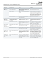
9.3 Warnings and Alarms 133
9.4 Troubleshooting 157
10 Specifications 160
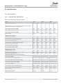
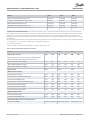
10.1 Electrical Data 160
10.1.1 Electrical Data, 380–480 V AC 160
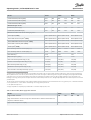
10.1.2 Electrical Data, 525–690 V AC 165
10.2 Mains Supply 170
10.3 Motor Output and Motor Data 170
10.3.1 Motor Output (U, V, W) 170
10.3.2 Torque Characteristics 170
10.4 Ambient Conditions 171
10.5 Control Cables 171
10.6 Control Input/Output and Control Data 171
10.6.1 Control Card, USB Serial Communication 171
10.6.2 STO Terminal XD2.19 (Terminal XD2.19 is Fixed PNP Logic) 172
10.6.3 Control Card, 24 V DC Output 172
10.6.4 Control Card, +10 V DC Output 172
10.6.5 Digital Outputs 172
10.6.6 Digital Inputs 173
10.6.7 Pulse/Encoder Inputs 173
10.6.8 Control Characteristics 174
10.6.9 Relay Outputs 174
10.6.10 Analog Output 175
10.6.11 Control Card, RS485 Serial Communication 175
10.6.12 Control Card Performance 175
10.6.13 Analog Inputs 175
10.7 Filter Specifications 176
10.7.1 Passive Harmonic Filter Specifications 176
10.7.2 Line Reactor Specifications 176
10.7.3 dU/dt Filter Specifications 177
10.7.4 Sine-wave Filter Specifications 178
10.8 Fuses and Circuit Breakers 179
10.8.1 Types of Fuses 179
10.8.2 Panel Fuses 180
Contents
Operating Guide | VLT® AQUA Drive FC 202
AQ262141056213en-000101 / 130R08826 | Danfoss A/S © 2018.10

10.8.3 Fusible Disconnect Switches 181
10.8.4 Non-fusible Disconnect Switches 182
10.8.5 Contactor Fuses 183
10.8.6 Molded-case Circuit Breakers 184
10.9 Enclosure Dimensions 185
10.9.1 Pedestal Dimensions 185
10.9.2 D9h Enclosed Drive Dimension 186
10.9.3 D10h Enclosed Drive Dimensions 187
10.9.4 E5h Enclosed Drive Dimensions 188
10.9.5 E6h Enclosed Drive Dimensions 189
10.10 Enclosure Airflow 190
10.11 Fastener Torque Ratings 190
11 Appendix 191
11.1 Conventions 191
11.2 Abbreviations 191
11.3 International/North American Default Parameter Settings 193
11.4 Required Parameter Settings for Drive Options 194
11.5 Block Diagrams 195
11.6 Input Power Option Losses 198
11.6.1 Contactor Losses 198
11.6.2 Fusible Disconnect Losses 199
11.6.3 Non-fusible Disconnect Losses 200
11.6.4 MCCB Losses 201
11.6.5 Passive Harmonic Filter Losses 202
11.6.6 dU/dt Filter Losses 203
11.6.7 Sine-wave Filter Losses 204
Contents
Operating Guide | VLT® AQUA Drive FC 202
AQ262141056213en-000101 / 130R0882 | 7Danfoss A/S © 2018.10

1 Introduction
1.1 Purpose of this Operating Guide
This operating guide provides information for safe installation and commissioning of the AC drive. It is intended for use by qualified
personnel. Read and follow the instructions to use the drive safely and professionally. Pay particular attention to the safety instructions
and general warnings. Always keep this operating guide available with the drive.
1.2 Additional Resources
Other resources are available to understand advanced drive functions and programming.
• The programming guide provides greater detail on working with parameters and shows many application examples.
• The design guide provides detailed information about capabilities and functionality to design motor control systems.
• The Safe Torque Off Operating Guide provides detailed specifications, requirements, and installation instructions for the Safe
Torque Off function.
• Supplementary publications and manuals are available from Danfoss.
See https://www.danfoss.com/en/search/?filter=type%3Adocumentation.
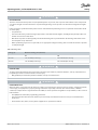
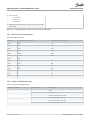
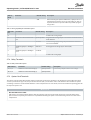
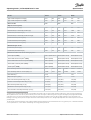
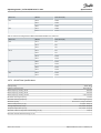
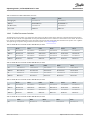
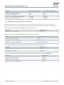
1.3 Manual Version
This manual is regularly reviewed and updated. All suggestions for improvement are welcome.
The original language of this manual is English.
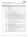
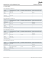
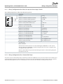
Table 1: Manual and Software Version
Version Remarks Software version
MG80H102 First version 3.31
1.4 Approvals and Certifications
The following list is a selection of possible type approvals and certifications for Danfoss drives:
089
Introduction
Operating Guide | VLT® AQUA Drive FC 202
AQ262141056213en-000101 / 130R0882
8 | Danfoss A/S © 2018.10

The specific approvals and certification for the enclosed drive are on the nameplate of the drive. For more information, contact the
local Danfoss office or partner.
Themal memory retention requirement
This enclosed drive complies with UL 508C and UL 61800-5-1 thermal memory retention requirements. The enclosed drive is UL listed
per UL508A and CSA 14 standards. For more information on UL 508C thermal memory retention requirements, refer to the Motor
Thermal Protection section in the product-specific design guide.
NOTICE
OUTPUT FREQUENCY LIMIT
Due to export control regulations, the output frequency of the drive is limited to 590 Hz. For demands exceeding 590 Hz,
contact Danfoss.
ADN-compliance
For more information on compliance with the European Agreement concerning International Carriage of Dangerous Goods by Inland
Waterways (ADN), refer to section ADN-compliant Installation in the product-specific design guide.
1.5 Disposal
Do not dispose of equipment containing electrical components together with domestic waste. Collect it separately in accordance with
applicable local regulations.
Introduction
Operating Guide | VLT® AQUA Drive FC 202
AQ262141056213en-000101 / 130R0882 | 9
Danfoss A/S © 2018.10

2 Safety
2.1 Safety Symbols
The following symbols are used in this manual:
DANGER
Indicates a hazardous situation which, if not avoided, will result in death or serious injury.
WARNING
Indicates a hazardous situation which, if not avoided, could result in death or serious injury.
CAUTION
Indicates a hazardous situation which, if not avoided, could result in minor or moderate injury.
NOTICE
Indicates a property damage message.
2.2 Qualified Personnel
To allow trouble-free and safe operation of the unit, only qualified personnel with proven skills are allowed to transport, store,
assemble, install, program, commission, maintain, and decommission this equipment.
Persons with proven skills:
• Are qualified electrical engineers, or persons who have received training from qualified electrical engineers and are suitably
experienced to operate devices, systems, plant, and machinery in accordance with pertinent laws and regulations.
• Are familiar with the basic regulations concerning health and safety/accident prevention.
• Have read and understood the safety guidelines given in all manuals provided with the unit, especially the instructions given in the
operating guide of the unit.
• Have good knowledge of the generic and specialist standards applicable to the specific application.
2.3 Safety Precautions
WARNING
LACK OF SAFETY AWARENESS
This document gives important information on how to prevent injury and damage to the equipment or your system. Ignoring
them can lead to death, serious injury, or severe damage to the equipment.
-
Make sure to fully understand the dangers and safety measures incurred in your application.
Safety
Operating Guide | VLT® AQUA Drive FC 202
AQ262141056213en-000101 / 130R0882
10 | Danfoss A/S © 2018.10

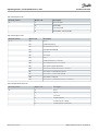
WARNING
DISCHARGE TIME
The drive contains DC-link capacitors and, if input filter options are present, extra capacitors and inductors. These components
can remain charged even when the drive is not powered. High voltage can be present even when the warning indicator lights
are off.
Failure to wait the specified time after power has been removed before performing service or repair work could result in death
or serious injury.
-
Stop the motor.
-
Disconnect AC mains, permanent magnet type motors, and remote DC-link supplies, including battery back-ups, UPS, and
DC-link connections to other drives.
-
Wait for the capacitors to discharge fully. The minimum waiting time is specified both in the Discharge Time table and on
the nameplate on top of the drive.
-
Before performing any service or repair work, use an appropriate voltage measuring device to make sure that the capacitors
are fully discharged.
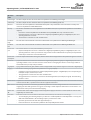
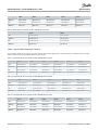
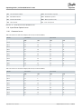
Table 2: Discharge Time
Voltage [V] Minimum waiting time (minutes)
20 40
380–480 110–315 kW (150–450 hp) 355–560 kW (500–750 hp)
525–690 110–400 kW (125–400 hp) 450–800 kW (450–950 hp)
WARNING
HIGH VOLTAGE
AC drives contain high voltage when connected to AC mains input. Failure to perform installation , start-up, and maintenance
by qualified personnel can result in death or serious injury.
-
Only qualified personnel must perform installation, start-up, and maintenance.
WARNING
UNINTENDED START
When the drive is connected to the AC mains, DC supply, or load sharing, the motor may start at any time, causing risk of death,
serious injury, and equipment, or property damage. The motor may start by activation of an external switch, a fieldbus
command, an input reference signal from the LCP or LOP, via remote operation using MCT 10 Set-up software, or after a cleared
fault condition.
-
Press [Off] on the LCP before programming parameters.
-
Disconnect the drive from the mains whenever personal safety considerations make it necessary to avoid unintended
motor start.
-
Check that the drive, motor, and any driven equipment is in operational readiness.
Safety
Operating Guide | VLT® AQUA Drive FC 202
AQ262141056213en-000101 / 130R0882 | 11
Danfoss A/S © 2018.10

WARNING
LEAKAGE CURRENT HAZARD
Leakage currents exceed 3.5 mA. Failure to ground the drive properly can result in death or serious injury.
-
Ensure the correct grounding of the equipment by a certified electrical installer.
WARNING
ROTATING SHAFTS
Contact with rotating shafts and electrical equipment can result in death or serious injury.
-
Ensure that only trained and qualified personnel perform installation, start-up, and maintenance.
-
Ensure that electrical work conforms to national and local electrical codes.
-
Follow the procedures in this guide.
CAUTION
HOT SURFACES
The drive contains metal components that are still hot even after the drive has been powered off. Failure to observe the high
temperature symbol (yellow triangle) on the drive can result in serious burns.
-
Be aware that internal components, such as busbars, may be extremely hot even after the drive has been powered off.
-
Do not touch exterior areas that are marked by the high temperature symbol (yellow triangle). These areas are hot while the
drive is in use and immediately after being powered off.
CAUTION
INTERNAL FAILURE HAZARD
An internal failure in the drive can result in serious injury when the drive is not properly closed.
-
Ensure that all safety covers are in place and securely fastened before applying power.
Safety
Operating Guide | VLT® AQUA Drive FC 202
AQ262141056213en-000101 / 130R0882
12 | Danfoss A/S © 2018.10

3 Product Overview
3.1 Intended Use
NOTICE
OUTPUT FREQUENCY LIMIT
Due to export control regulations, the output frequency of the drive is limited to 590 Hz. For demands exceeding 590 Hz,
contact Danfoss.
The enclosed drive is an electronic motor controller that converts AC mains input into a variable AC waveform output. The frequency
and voltage of the output are regulated to control the motor speed or torque. Depending on the configuration, the drive can be used
in standalone applications or form part of a larger system or installation. The enclosed drive is designed to:
• Regulate motor speed in response to system feedback or remote commands from external controllers.
• Provide motor overload protection.
• Monitor system and motor status.
• Reduce harmonics and increase the power factor using the optional passive harmonic filter or line reactor.
• Reduce motor acoustic noise and protect motor insulation with the optional output filters.
• Reduce bearing current and shaft voltage with the optional common-mode filter.
• Reduce high-frequency, electromagnetic noise in the motor cables with the optional dU/dt filter.
• Provide sinusoidal output with optional sine-wave filter.
The enclosed drive is designed for residential, industrial, and commercial environments in accordance with local laws and standards.
Do not use this drive in applications that are non-compliant with specified operating conditions and environments.
NOTICE
RADIO INTERFERENCE
In a residential environment, this product can cause radio interference.
-
Take supplementary mitigation measures.
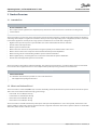
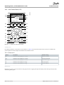
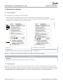
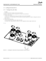
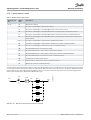
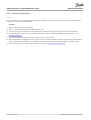
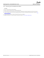
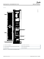
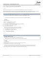
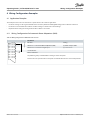
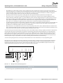
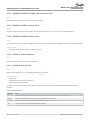
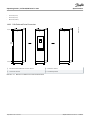
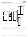
3.2 What is an Enclosed Drive?
The enclosed drive is an IP21/54 (NEMA 1/12) enclosure surrounding an IP20 (Protected Chassis) drive to form the basis of the system.
There are 4 enclosed drive models with varying power ratings.
• D9h model: 110–160 kW (125–250 hp)
• D10h model: 200–400 kW (250–450 hp)
• E5h model: 355–630 kW (450–650 hp)
• E6h model: 500–800 kW (650–950 hp)
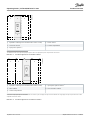
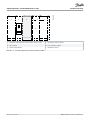
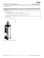
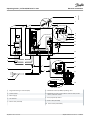
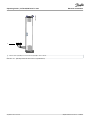
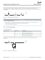
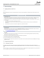
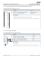
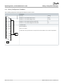
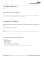
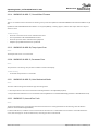
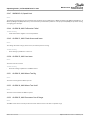
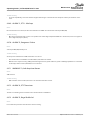
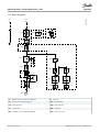
The enclosed drive is available with various power options and input and output filters to create a factory-built, custom drive. Some
options and filters result in extra cabinets attached to the left or right side of the drive cabinet. These optional cabinets are shown with
dotted lines, while the drive cabinet is shaded.
Product Overview
Operating Guide | VLT® AQUA Drive FC 202
AQ262141056213en-000101 / 130R0882 | 13
Danfoss A/S © 2018.10

e30bu152.10
1
3
2
4
5
1 Input filter cabinet (passive harmonic filter or line reactor)
3 Sine-wave cabinet
5
Input power options
(1)
2 Drives cabinet
4 Control compartment
1
The D9h enclosure does not require an input power options cabinet – the input power options are placed in the drive cabinet.
Illustration 1: Possible Configurations for a D9h Enclosed Drive
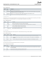
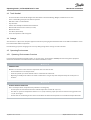
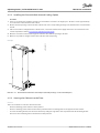
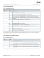
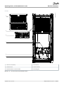
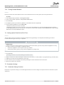
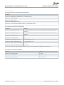
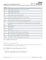
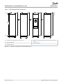
e30bu067.10
1
2
4
5
3
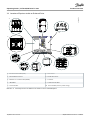
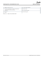
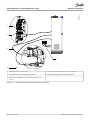
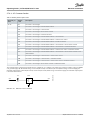
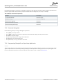
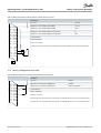
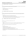
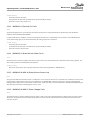
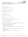
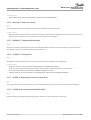
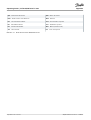
1 Input filter cabinet (passive harmonic filter or line reactor)
3 Drive cabinet
5 Control compartment
2
Input power options cabinet
(1)
4 Sine-wave filter cabinet
1
If more than 1 input power option is ordered, the D10h enclosed drive requires an input power options cabinet. Otherwise the single input power option is placed below the control
compartment in the drive cabinet.
Illustration 2: Possible Configurations for a D10h Enclosed Drive
Product Overview
Operating Guide | VLT® AQUA Drive FC 202
AQ262141056213en-000101 / 130R0882
14 | Danfoss A/S © 2018.10

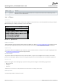
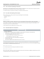
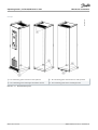
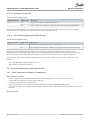
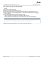
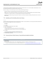
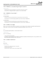
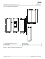
e30bu068.10
1
2
4
3
6
5
3
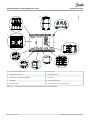
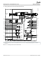
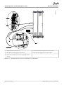
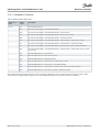
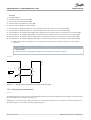
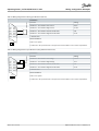
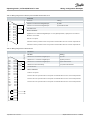
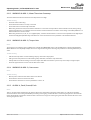
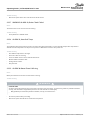
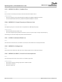
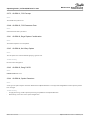
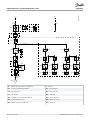
1 Input filter cabinet (passive harmonic filter or line reactor)
3 Drive cabinet
5 Control compartment
2 Input power options cabinet
4 Sine-wave filter cabinet
6 dU/dt filter cabinet
Illustration 3: Possible Configurations for an E5h or E6h Enclosed Drive
Product Overview
Operating Guide | VLT® AQUA Drive FC 202
AQ262141056213en-000101 / 130R0882 | 15
Danfoss A/S © 2018.10

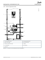
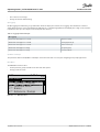
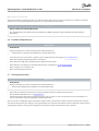
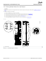
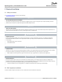
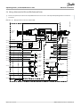
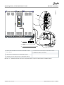
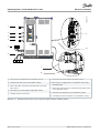
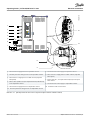
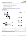
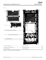
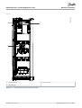
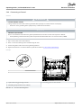
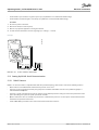
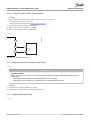
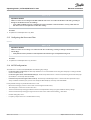
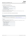
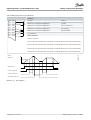
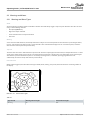
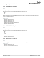
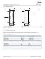
3.3 Location of Options within an Enclosed Drive
e30bu177.10
1
2
3
4
5
6
7
8
9
10
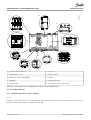
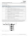
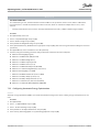
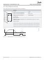
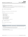
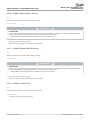
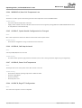
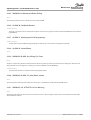
1 Passive harmonic filter (PHF)
3 Non-fusible disconnect
5 Molded-case circuit breaker (MCCB)
7 dU/dt filter
9 Sine-wave filter
2 Line reactor
4 Fusible disconnect
6 Contactor
8 Common-mode filter
10 Drive module (varies in power rating)
Illustration 4: Visual Representation of a D9h Enclosure and the Locations of Available Options
Product Overview
Operating Guide | VLT® AQUA Drive FC 202
AQ262141056213en-000101 / 130R0882
16 | Danfoss A/S © 2018.10

e30bu178.10
1
2
3
4
5
6
7
8
9
10
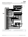
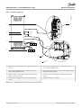
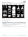
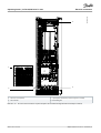
1 Passive harmonic filter (PHF)
3 Non-fusible disconnect
5 Molded-case circuit breaker (MCCB)
7 dU/dt filter
9 Sine-wave filter
2 Line reactor
4 Fusible disconnect
6 Contactor
8 Common-mode filter
10 Drive module (varies in power rating)
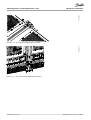
Illustration 5: Visual Representation of a D10h Enclosure and the Locations of Available Options
Product Overview
Operating Guide | VLT® AQUA Drive FC 202
AQ262141056213en-000101 / 130R0882 | 17
Danfoss A/S © 2018.10

e30bu141.10
1
2
3
4
5
6
7
8
9
10
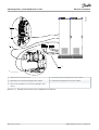
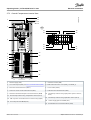
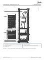
1 Passive harmonic filter (PHF)
3 Non-fusible disconnect
5 Molded-case circuit breaker (MCCB)
7 dU/dt filter
9 Sine-wave filter
2 Line reactor
4 Fusible disconnect
6 Contactor
8 Common-mode filter
10 Drive module (varies in power rating)
Illustration 6: Visual Representation of a E5h/E6h Enclosure and the Locations of Available Options
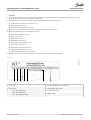
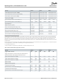
3.4 Drive Identification
3.4.1 Identifying the Drive and Its Options
Context:
Enclosure size and specific options are used throughout this guide whenever procedures or components differ based on the drive and
its options. Use the following steps to identify the enclosed drive:
Product Overview
Operating Guide | VLT® AQUA Drive FC 202
AQ262141056213en-000101 / 130R0882
18 | Danfoss A/S © 2018.10

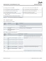
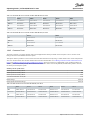
Procedure
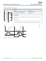
1. Locate the type code (T/C) on the nameplate. The nameplate is found on the exterior of the drive by the bottom grill or on the
inside cabinet door that contains the control compartment.
2. Determine the type of enclosure by obtaining the following information from the type code:
A Product group and drive series (characters 1–6).
B Voltage rating (character 8).
C Model/power rating (characters 10–12).
3. Go to
table 3 and use the model number and voltage rating to find the enclosure size.
4. Obtain the following option codes from the type code.
A Low harmonic filter (character 7).
B Brake (character 15).
C Mains (character 16–17).
D Output filter (character 18).
E Extra empty cabinet (character 19).
F Cable infeed (character 20).
G Back-channel cooling (character 22).
H Auxiliary function (characters 22–23).
I Door-mounted options (characters 28–29).
5. Using the option codes, refer to
3.4.3 Option Code Identification to identify the installed options.
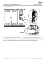
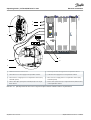
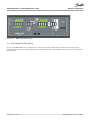
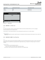
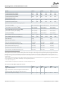
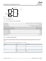
Example:
e30bu139.10
1
2
3
4
5
6 7 8
1 Type code.
3 Drive series
• 102 = VLT
®
HVAC Drive
• 202 = VLT
®
AQUA Drive
• 302 = VLT
®
AutomationDrive
2 Product group (PLV = enclosed drive)
4 Low harmonic filter option
6 Model/power rating
8 Option codes
Product Overview
Operating Guide | VLT® AQUA Drive FC 202
AQ262141056213en-000101 / 130R0882 | 19
Danfoss A/S © 2018.10

5 Mains voltage
• 4 = 380–480 V
• 5 = 380–500 V
• 6 = 525–690 V
7 Build date (wwy, where ww = the week and y = the last digit
of the year)
Illustration 7: Using the Nameplate to Find the Enclosure Size and Installed Options
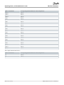
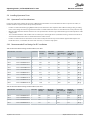
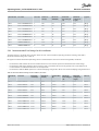
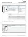
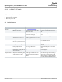
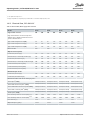
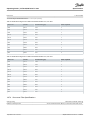
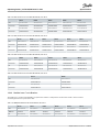
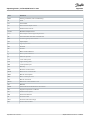
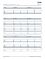
3.4.2 Enclosure Size Identification
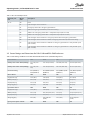
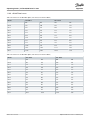
Table 3: Model by Drive Voltage
Model Enclosure size (380–480 V) Enclosure size (525–690 V)
N110 D9h D9h
N132 D9h D9h
N160 D9h D9h
N200 D10h D10h
N250 D10h D10h
N315 D10h D10h
N355 E5h –
N400 E5h D10h
N450 E5h E5h
N500 E6h E5h
N560 E6h E5h
N630 – E5h
N710 – E6h
N800 – E6h
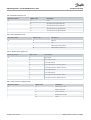
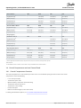
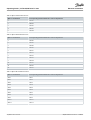
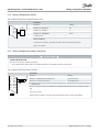
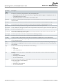
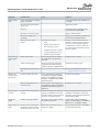
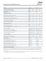
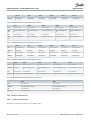
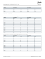
3.4.3 Option Code Identification
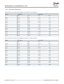
Table 4: Low-harmonic Filter Option Codes
Character position Option code Description
7 T None
A Active filter
P Passive filter, THDi=5%, 50 Hz
H Passive filter, THDi=8%, 50 Hz
L Passive filter, THDi=5%, 60 Hz
U Passive filter, THDi=8%, 60 Hz
Product Overview
Operating Guide | VLT® AQUA Drive FC 202
AQ262141056213en-000101 / 130R0882
20 | Danfoss A/S © 2018.10
Page is loading ...
Page is loading ...
Page is loading ...
Page is loading ...
Page is loading ...
Page is loading ...
Page is loading ...
Page is loading ...
Page is loading ...
Page is loading ...
Page is loading ...
Page is loading ...
Page is loading ...
Page is loading ...
Page is loading ...
Page is loading ...
Page is loading ...
Page is loading ...
Page is loading ...
Page is loading ...
Page is loading ...
Page is loading ...
Page is loading ...
Page is loading ...
Page is loading ...
Page is loading ...
Page is loading ...
Page is loading ...
Page is loading ...
Page is loading ...
Page is loading ...
Page is loading ...
Page is loading ...
Page is loading ...
Page is loading ...
Page is loading ...
Page is loading ...
Page is loading ...
Page is loading ...
Page is loading ...
Page is loading ...
Page is loading ...
Page is loading ...
Page is loading ...
Page is loading ...
Page is loading ...
Page is loading ...
Page is loading ...
Page is loading ...
Page is loading ...
Page is loading ...
Page is loading ...
Page is loading ...
Page is loading ...
Page is loading ...
Page is loading ...
Page is loading ...
Page is loading ...
Page is loading ...
Page is loading ...
Page is loading ...
Page is loading ...
Page is loading ...
Page is loading ...
Page is loading ...
Page is loading ...
Page is loading ...
Page is loading ...
Page is loading ...
Page is loading ...
Page is loading ...
Page is loading ...
Page is loading ...
Page is loading ...
Page is loading ...
Page is loading ...
Page is loading ...
Page is loading ...
Page is loading ...
Page is loading ...
Page is loading ...
Page is loading ...
Page is loading ...
Page is loading ...
Page is loading ...
Page is loading ...
Page is loading ...
Page is loading ...
Page is loading ...
Page is loading ...
Page is loading ...
Page is loading ...
Page is loading ...
Page is loading ...
Page is loading ...
Page is loading ...
Page is loading ...
Page is loading ...
Page is loading ...
Page is loading ...
Page is loading ...
Page is loading ...
Page is loading ...
Page is loading ...
Page is loading ...
Page is loading ...
Page is loading ...
Page is loading ...
Page is loading ...
Page is loading ...
Page is loading ...
Page is loading ...
Page is loading ...
Page is loading ...
Page is loading ...
Page is loading ...
Page is loading ...
Page is loading ...
Page is loading ...
Page is loading ...
Page is loading ...
Page is loading ...
Page is loading ...
Page is loading ...
Page is loading ...
Page is loading ...
Page is loading ...
Page is loading ...
Page is loading ...
Page is loading ...
Page is loading ...
Page is loading ...
Page is loading ...
Page is loading ...
Page is loading ...
Page is loading ...
Page is loading ...
Page is loading ...
Page is loading ...
Page is loading ...
Page is loading ...
Page is loading ...
Page is loading ...
Page is loading ...
Page is loading ...
Page is loading ...
Page is loading ...
Page is loading ...
Page is loading ...
Page is loading ...
Page is loading ...
Page is loading ...
Page is loading ...
Page is loading ...
Page is loading ...
Page is loading ...
Page is loading ...
Page is loading ...
Page is loading ...
Page is loading ...
Page is loading ...
Page is loading ...
Page is loading ...
Page is loading ...
Page is loading ...
Page is loading ...
Page is loading ...
Page is loading ...
Page is loading ...
Page is loading ...
Page is loading ...
Page is loading ...
Page is loading ...
Page is loading ...
Page is loading ...
Page is loading ...
Page is loading ...
Page is loading ...
Page is loading ...
Page is loading ...
Page is loading ...
Page is loading ...
Page is loading ...
Page is loading ...
Page is loading ...
Page is loading ...
-
 1
1
-
 2
2
-
 3
3
-
 4
4
-
 5
5
-
 6
6
-
 7
7
-
 8
8
-
 9
9
-
 10
10
-
 11
11
-
 12
12
-
 13
13
-
 14
14
-
 15
15
-
 16
16
-
 17
17
-
 18
18
-
 19
19
-
 20
20
-
 21
21
-
 22
22
-
 23
23
-
 24
24
-
 25
25
-
 26
26
-
 27
27
-
 28
28
-
 29
29
-
 30
30
-
 31
31
-
 32
32
-
 33
33
-
 34
34
-
 35
35
-
 36
36
-
 37
37
-
 38
38
-
 39
39
-
 40
40
-
 41
41
-
 42
42
-
 43
43
-
 44
44
-
 45
45
-
 46
46
-
 47
47
-
 48
48
-
 49
49
-
 50
50
-
 51
51
-
 52
52
-
 53
53
-
 54
54
-
 55
55
-
 56
56
-
 57
57
-
 58
58
-
 59
59
-
 60
60
-
 61
61
-
 62
62
-
 63
63
-
 64
64
-
 65
65
-
 66
66
-
 67
67
-
 68
68
-
 69
69
-
 70
70
-
 71
71
-
 72
72
-
 73
73
-
 74
74
-
 75
75
-
 76
76
-
 77
77
-
 78
78
-
 79
79
-
 80
80
-
 81
81
-
 82
82
-
 83
83
-
 84
84
-
 85
85
-
 86
86
-
 87
87
-
 88
88
-
 89
89
-
 90
90
-
 91
91
-
 92
92
-
 93
93
-
 94
94
-
 95
95
-
 96
96
-
 97
97
-
 98
98
-
 99
99
-
 100
100
-
 101
101
-
 102
102
-
 103
103
-
 104
104
-
 105
105
-
 106
106
-
 107
107
-
 108
108
-
 109
109
-
 110
110
-
 111
111
-
 112
112
-
 113
113
-
 114
114
-
 115
115
-
 116
116
-
 117
117
-
 118
118
-
 119
119
-
 120
120
-
 121
121
-
 122
122
-
 123
123
-
 124
124
-
 125
125
-
 126
126
-
 127
127
-
 128
128
-
 129
129
-
 130
130
-
 131
131
-
 132
132
-
 133
133
-
 134
134
-
 135
135
-
 136
136
-
 137
137
-
 138
138
-
 139
139
-
 140
140
-
 141
141
-
 142
142
-
 143
143
-
 144
144
-
 145
145
-
 146
146
-
 147
147
-
 148
148
-
 149
149
-
 150
150
-
 151
151
-
 152
152
-
 153
153
-
 154
154
-
 155
155
-
 156
156
-
 157
157
-
 158
158
-
 159
159
-
 160
160
-
 161
161
-
 162
162
-
 163
163
-
 164
164
-
 165
165
-
 166
166
-
 167
167
-
 168
168
-
 169
169
-
 170
170
-
 171
171
-
 172
172
-
 173
173
-
 174
174
-
 175
175
-
 176
176
-
 177
177
-
 178
178
-
 179
179
-
 180
180
-
 181
181
-
 182
182
-
 183
183
-
 184
184
-
 185
185
-
 186
186
-
 187
187
-
 188
188
-
 189
189
-
 190
190
-
 191
191
-
 192
192
-
 193
193
-
 194
194
-
 195
195
-
 196
196
-
 197
197
-
 198
198
-
 199
199
-
 200
200
-
 201
201
-
 202
202
-
 203
203
-
 204
204
-
 205
205
-
 206
206


Danfoss VLT AQUA Drive FC202, 100-800kW Op.Guide User guide
- Type
- User guide
- This manual is also suitable for
Ask a question and I''ll find the answer in the document
Finding information in a document is now easier with AI
Related papers
-
Danfoss VLT® Refrigeration Drive FC103 110-800kW User guide
-
Danfoss VLT HVAC Drive FC 102 110-800kW Op.Guide User guide
-
Danfoss VLT AutomationDrive FC 302 User guide
-
Danfoss VLT AQUA Drive FC 202 User guide
-
-
-
-
-
-
Danfoss VLT 6000 (Legacy Product) User guide
Other documents
-
NSI PL3/0-6 Installation guide
-
Pulsar AWZ510 Operating instructions
-
-
Haier ABH125K5ERG 12.5 kW Round Way Cassette User guide
-
 Artesis MCM Quick Installation Manual
-
ABB free@home SUG-F-1.1 User manual
-
Emerson XDF User manual
-
WEG SSW-03 Quick start guide
-
 Red Rock 8585176 Owner's manual
-
ABB ACS 6000 Commissioning Manual

