Page is loading ...

CAW
Cassette Ductless
Chilled Water
Air Handlers
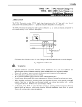
Nominal Capacities
CAW08 CAW12 CAW18 CAW20 CAW33 CAW36 Units
8,000 12,000 18,000 20,000 33,000 36,000 Btuh
2.3 3.5 5.3 5.9 9.7 10.6 kW
Installation, Operation and
Maintenance Manual
MODELS CAW 08-12
SHOWN
MODELS CAW 33-36
SHOWN
P/N# 240009722, Rev. D [7/22/2013]
An ISO 9001-2008 Certied Company
ECR International, Inc.
2201 Dwyer Avenue,
Utica NY 13501
web site:www.enviromaster.com

TABLE OF CONTENTS
Check our website frequently for updates: www.enviromaster.com
time of printing of this manual. Manufacturer reserves the right to
Receiving Information ................................................................................................................ 3
Important Safety Information ..................................................................................................... 4
General Product Information ....................................................................................................... 5
Dimensional/Physical Data ......................................................................................................... 6
Unit Mounting ........................................................................................................................... 9
Condensate Piping ....................................................................................................................12
Duct Connections .....................................................................................................................13
Final Assembly ........................................................................................................................14
Electrical Wiring .......................................................................................................................16
115V Option ............................................................................................................................16
Thermostat Operation ...............................................................................................................19
Initial Start-Up — CAWA Wall Mounted Remote Thermostat Only ....................................................20
Initial Start-Up — CAWB Infrared Handheld Remote Thermostat .....................................................22
CAWB Infrared Handheld Remote Microprocessor Controller Overview .............................................24
CAWB Infrared Handheld Remote Controller Setting ...................................................................... 28
CAWB Infrared Handheld Remote Controller Operation ..................................................................32
CAWB Infrared Handheld Remote Thermostat Operation ................................................................35
CAWB Infrared Handheld Remote Thermostat Controller Fault Conditions .........................................36
Maintenance ............................................................................................................................37
Troubleshooting ......................................................................................................................38
Specications & System Performance .......................................................................................... 40
2
Unit has been tested and
rated in accordance with:
ANSI/AHRI Standards
440-2008
UL-1995

RECEIVING INFORMATION
General Information
• Installation shall be completed by qualied agency.
• Installer - This manual is property of owner. Leave with
owner when installation is complete.
• Owner - Retain this manual and warranty for future
reference.
Receiving Inspection
• Inspect unit for damage. Report any shipping damage
to carrier immediately.
• Check rating plate on unit. Verify power supply meets
available electric power for installation.
• Verify unit received meets description of product
ordered, including applicable specications.
When requesting assistance, please have following
information available:
Model Number_________________________
Serial Number_________________________
Date of installation______________________
3

IMPORTANT SAFETY INFORMATION
All eld wiring shall conform to requirements of authority
having jurisdiction or in absence of such requirements:
• United States - National Electrical Code, ANSI/NFPA 70
Unit must be electrically grounded in conformance to
this code.
• Canada - CSA C22.1 Canadian Electrical Code Part 1.
• Have a qualied service agency install and service this
appliance.
• Turn off electrical supply before servicing unit.
• Inspect all parts for damage prior to installation and
start-up.
• Do not use unit if it has damaged wiring, is not working
properly, or has been damaged or dropped.
• Connect to properly grounded electrical supply with
proper voltage as stated on rating plate.
• Have proper over-current protection (i.e. time-delay
fuse/HACR Breaker) as listed on Rating Plate.
• Verify there are no power feeds to unit such as re
alarm circuits, BMS circuits, etc.
• Service or repair of unit using manufacturer approved
replacement parts only.
• Do not use any mechanical or electrical controllers which
have been wet. Replace any defective controller.
• Do not support any part of ceiling with appliance,
associated wiring or pipe work.
• Check rating plate on unit before installation. Verify
voltage shown is same as electric supply to unit. Rating
plate is located on top panel.
DANGER
Indicates a hazardous situation which, if not
avoided, WILL result in death or serious injury.
!
WARNING
Indicates a hazardous situation which, if not
avoided, could result in death or serious injury.
!
CAUTION
Indicates a hazardous situation which, if not
avoided, could result in minor or moderate injury.
!
NOTICE
Indicates information which should be followed to
ensure proper installation and operation.
WARNING
Electrical shock hazard. Improper assembly and/
or installation could result in death or serious injury.
Have a qualied service agency install and service
this appliance. Read this manual and understand all
requirements before beginning installation.
!
WARNING
Tampering with this unit is dangerous and could
result in serious injury or death. Do not modify or
change this unit.
!
4

GENERAL PRODUCT INFORMATION
Product Description
• Available in three cabinet sizes with six output
capacities from 8,000–36,000 Btuh.
• Available in 115V and 208/230V.
• Factory installed electric heat option. No eld installed
electric heat kits are available.
• Designed for low noise levels, easy installation, easy
maintenance and slim line fascia, insure minimum
intrusion into conditioned environment.
• Galvanized steel cabinet with re-resistant thermal and
acoustic foam insulation.
• Expanded polystyrene drain pan with tough, re
retardant thermoplastic liner.
• 24V wall thermostat connections, thermostat not
included.
• Controls also feature anti-short-cycle timer, post purge
fan relay, and an on-board 30 amp electric heat relay.
• 24V Transformer.
• See thermostat requirements in this manual.
• Light grey high-impact ABS fascia.
• All units can be operated using a wall thermostat.
Remote Thermostat Application (Wall mounted)
• Units require remote thermostat for operation. On-
board controller is not included.
• Controller offers limited options when operated by
remote thermostat.
(Otional) Infrared Hand Held Remote Thermostat
Applications
Infrared hand held remote uses a custom control board
featuring programmability, conguration and multiple
modes of operation.
• Units include on-board microprocessor controller with
infrared hand held remote.
• Infrared hand held remote is required to adjust settings
and congure controller.
• Bank of DIP switches for setting operation is included.
• Custom control board featuring programmability,
conguration, and multiple modes of operation.
• User accessible permanent, washable, lter which may
be vacuum cleaned.
• Branch duct knockouts on three sides for remote
discharge locations; use two non-adjacent sides.
• Fresh air intake capability on three sides of cabinet;
only two on models 08–12.
• Four plastic air vanes, motor driven with auto sweep
or xed position stop setting on models 18-36. Models
08–12 are equipped with manually-adjusted air vanes.
• Fans are backward curved impeller centrifugal design:
dynamically and statically balanced; and mounted on
integral mounting rails.
-Single fan models 08, 12, 18 and 20 are designed
with re-retardant plastic or aluminum impellers.
-Twin fan models 33 and 36 are designed with re
retardant plastic impellers.
-Multispeed motors are enclosed type with thermal
protection and sealed bearings.
Coil
• Coil is seamless, copper tubing, arranged in staggered
conguration, with enhanced aluminum ns, tested to
250 psig.
• Tubes are mechanically expanded for secure bonding to
n shoulder.
• 24V wall thermostat.
• Electric Heat (@ 230V)
– 1.5 kW — models 8–12
– 3 kW — models 18-20
– 5 kW — models 33-36
Mechanical Characteristic
Metal framed lters are tted, reusable.
Condensate Pump
• Carries water out of unit. Pump is xed to mounting
bracket, can be withdrawn from side of chassis.
Inspection hole allows visual check of pump during
operation.
• Float switch stops cooling action, shuts off water valve
if pump becomes blocked or fails.
• Pump total lift is 36” (0.9 m) or less measured from
base or bottom of unit.
Air Vanes
• Manually adjustable air outlet vanes models 08-12 or
electric motor driven on models 18-36.
• Motorized air vanes can be set to auto sweep or
stopped in xed position.
Fresh Air Connection
• May introduce fresh air to unit by addition of ducts
connected to fresh air knockouts on cassette case.
• Manufacturer recommended maximum length is 10’
(3m) of 4” (0.1m) diameter duct. Fresh air volume is
approximately 7–10% of unit’s published maximum air
ow if more than 10% make up air is needed fresh air
booster fan is required.
Heating
• Cassette may be tted with optional heaters equipped
with over-temperature limit switches.
5

DIMENSIONAL/PHYSICAL DATA
Figure 1 - Dimensions: Models 8, 12
25"
25"
2
13
16
"
1
3
8
"
1
2
12
3
4
"
25
13
16
"
1
13
16
"
5
1
8
"
11
5
16
"
12
5
8
"
1
3
8
"
2
3
16
"
1
2
22
1
2
"
25
15
16
" with 115v Transformer
1
1
4
"
7
5
8
"
11
1
4
"
5
1
8
"
2 2
1
1
4
"
4
3
16
"
22
13
16
"
19
1
2
"
3
13
16
"
4
7
8
"
5
1
4
"
5
3
4
"
2
11
16
"
3
5
8
"
MODELS 08-12 BTU
3
6
DETAIL A
SCALE 1 : 2
4
5
FEATURES
1
Optional Discharge
Knockouts 5 ¼” Diameter
(3 Available)
2
FRESH AIR INLET KNOCKOUTS
1 1/4 x 2 1/2 Inches
2 Available
3
Condensate Discharge
1/2 inch Diameter
4
Water Connection "IN"
5
Water Connection "OUT"
6
Condensate Pump Access Panel
6

DIMENSIONAL/PHYSICAL DATA
Figure 2 - Dimensions: Models 18-20
37"
37"
5
1
2
"
3
1
8
"
4
1
2
"
5
1
2
"
4
1
2
"
5
11
16
"
3
5
4
6
35
9
16
"
18
11
16
"
1
15
16
"
5
1
8
"
12
1
16
"
13
1
16
"
2
7
8
"
1
7
8
"
1
2
3
5
8
"
1
11
16
"
1
2
5
1
8
"
16
1
4
"
32
7
16
"
35
7
8
" with 115v Transformer
1
1
2
"
7
5
8
"
1
2 2
1
9
16
"
4
3
16
"
30
13
16
"
29
3
16
"
FEATURES
1
Optional Discharge
Knockouts 5 ¼” Diameter
(3 Available)
2
FRESH AIR INLET KNOCKOUTS
1 1/4 x 2 1/2 Inches
2 Available
3
Condensate Discharge
1/2 inch Diameter
4
Water Connection "OUT"
5
Water Connection "IN"
6
Condensate Pump Access Panel
7

DIMENSIONAL/PHYSICAL DATA
Figure 3 - Dimensions: Models 33-36
37"
49
1
4
"
5
3
8
"
3
3
8
"
4
5
16
"
5
3
8
"
5
5
8
"
4
5
8
"
3 5
4
6
1
1
4
"
10"
37
1
2
" with 115v Transformer
32
7
16
"
16
1
4
"
5
1
8
"
1
2
2
3
5
8
"
1
11
16
"
1
2
47
13
16
"
24
13
16
"
1
15
16
"
5
1
8
"
14
1
8
"
1
7
8
"
3
3
8
"
1
2
1
5
16
"
5
7
8
"
43
1
16
"
29
3
16
"
FEATURES
1
Optional Discharge
Knockouts 5 ¼” Diameter
(3 Available)
2
FRESH AIR INLET KNOCKOUTS
1 1/4 x 2 1/2 Inches
2 Available
3
Condensate Discharge
1/2 inch Diameter
4
Water Connection "IN"
5
Water Connection "OUT"
6
Condensate Pump Access Panel
8

Unpacking
NOTICE
Do not throw template away with packaging. See
Figure 8 page 10.
Do not use drain or water connections for lifting.
Cassette fascia and main chassis are packaged together.
1.
Remove banding straps and lift cardboard lid.
2.
Fascia is packed in bubble wrap on top of chassis.
Fascia is not attached to chassis for shipping.
3.
Cardboard template is between chassis and fascia. See
Figure 8 page10.
4.
Lift fascia and template from box and set aside.
5.
Remove cassette chassis from box utilizing four corner
brackets for lifting.
6.
To protect fascia from dirt and damage return them to
box until ready to install.
7.
Do not throw away two polystyrene blanking-off pieces
with packaging. See Figure 6.
Blanking Off
Fascia discharge slot(s) need blanking off when ducts are
used to channel conditioned air to other areas.
• Position two polystyrene blanking off strips (provided)
in fascia discharge slots to direct air to ducts.
• Up to two non-adjacent sides may be blanked off.
Figure 6
1.
Remove inlet grilles and lters. See Figure 4 and
Figure 5.
2.
Turn fascia over to expose polystyrene insulation.
3.
Push one polystyrene blanking-off pieces into recess in
polystyrene fascia insulation.
UNIT MOUNTING
Figure 4
One Grille & One Filter
Hinge
Figure 5
Blanking-Off
Pieces
Figure 6
9

Positioning
Select cassette installation position.
1.
Pipe work, electrical connections, control box and
condensate pump access panels should be readily
accessible. Refer to cassette dimensions. See Figures 1,
2 & 3.
2.
Position unit at least 5 ft. (1.5m) from wall or similar
obstruction.
3.
Position unit as close to center of room as possible to
insure even air distribution.
4.
Position unit so discharge air does not blow directly on
remote wall wired thermostat, if used.
5.
Do not position unit directly above any obstructions.
6.
Verify Condensate drain has sufcient fall — 1” per 10’
(8 mm/m) in any horizontal run between cassette and
drain.
7.
Maximum condensate pump lift is 36” (0.9m) from
bottom of unit.
8.
Maintain minimum 1” (25.4mm) clearance above
cassette depth and false ceiling for proper installation.
See Figure 7.
9.
Cut opening in false ceiling using size shown in Table 1.
Wired Wall Thermostat (not supplied)
Locate wired wall mounted thermostat to ensure good
temperature control. Select installation position.
1.
Position thermostat approximately 5 ft. (1.5m) above
oor level.
2.
Avoid external walls and drafts from windows and
doors.
3.
Avoid positioning near shelves and curtains as these
restrict air movement.
4.
Avoid heat sources (direct sunlight, heaters, dimmer
switches, etc.)
5.
Seal wiring holes in wall behind thermostat to avoid
drafts.
UNIT MOUNTING
Ceiling For Installation
A
A
+1”
Model Dimension A
08 & 12 12 5/8” (0.32 m) min.
18 & 20 13 1/16” (0.33 m) min.
33 & 36 15 5/8" (0.40 m) min.
Ceiling Opening
NOTICE
Verify ceiling grid is supported separately from
cassette. Do not support ceiling by any part of
cassette unit, fascia or any associated wiring or pipe
work.
Model Dimensions
08 & 12 23 ¼” x 23 ¼” (591 x 591 mm)
18 & 20 33 ⅞” x 33 ⅞” (860 x 860 mm)
33 & 36 33 ⅞” x 46" (860 mm x 1168 mm)
Figure 7 - Spacing Requirements
(51MM X 45°)
2.000 X 45° TYP
Rod
Positions
1.500 TYP
Rod
Positions
(38MM TYP)
Figure 8 - Ceiling Cutout/Rod Placement
Template (Shipped With Unit)
A
10

Figure 9 - Mounting Brackets
Fold
bracket along
perforations
Mounting Method
• In existing construction, remove enough ceiling panels
to provide clearance space for mounting unit to ceiling
joists.
• Before beginning installation, inspect unit location, test
strength of ceiling joists to ensure they will support unit
weight.
• Determine mounting method:
A. Wooden beams use threaded rods, washers, and
nuts to suspend support brackets.
B. Metal structures, secure threaded rods on existing
angle or install new support angle.
C. Newly built concrete slabs secure threaded rods
with inserts and embedded bolts.
D. For previously built concrete slabs install hanging
bolts with expansion anchor.
• Follow local building codes for required safety cables,
braces, etc.
- Ceiling Rod Positions
A
A
B
Model Dimension A Dimension B
08 & 12 19.50” (495mm) 22.87” (581mm)
18 & 20 29.19” (740mm) 30.80” (782mm)
33 & 36 29.19” (740mm) 43.06” (1094mm)
UNIT MOUNTING
Figure 10 - Positioning Installation Guides
INNER CASE
INSULATION
CASSETTE
CASE
Figure 11 -Threaded Rods Must Not Protrude
Brackets
MAXIMUM
2”
(51mm)
Mounting
1.
Use template to cut ceiling opening and determine rod
positions. See Figure 8, Page 10.
2.
Install hanger bolts using 3/8” (10mm) all-thread rod
at centers. See Table 2.
3.
Prepare installation guides by folding metal bracket by
hand along perforations. See Figure 9.
4.
Lift cassette onto hanging rods.
5.
Level at correct distance from ceiling with aid of
installation guides. See Figure 10.
6.
Secure unit in position with locknuts and washers on
either side of cassette bracket.
7.
Insure threaded rod does not protrude more than 2”
(51mm) below mounting bracket. See Figure 11.
8.
If ceiling is not level or even, install cassette level to
ensure correct pump operation and to maintain fan
clearances.
9.
Place carpenter’s level on unit.
10.
Maximum slope of 1/8” (3mm) over length of chassis
toward condensate drain is allowed. Slight discrepancy
between cassette and ceiling will be taken up by fascia
foam seal.
11

Cassette is supplied with 1/2” I.D. exible PVC hose for
connection to copper or plastic drain piping. See Figure 13.
Condensate Piping
1.
Maximum pump lift is 36” (0.9m) from base or bottom
of unit.
2.
Highest point in condensate piping should be as close
to unit as possible. Prevents large volume of water
draining back into unit when it is switched off. See
Figure 12.
3.
Check valve at pump discharge to prevent water from
draining back into unit. Piping technique minimizes
issues if check valve is stuck open from airborne
debris.
4.
Slope condensate pipe-work downward from highest
point in direction of water ow with minimum gradient
of 1” per 10’ (8mm/1m). No uphill gradients except
in rst 18” (0.45m) of pipe-work from cassette. See
Figure 125.
5.
When multiple cassettes are connected to common
condensate drain, ensure drain is large enough to
handle total volume of condensate.
6.
Drain line vent may be required to prevent siphoning of
water from drain pan and associated noise.
Figure 12 - Highest Point Of Condensate Piping
Correct
Incorrect
Figure 13 - Condensate Drain
Condensate Drain Connection
CONDENSATE PIPING
NOTICE
Insulate chilled water and condensate pipes up to
chassis to prevent condensation which may damage
ceiling and objects located below.
Insulate chilled water valves to prevent sweating.
12

Attach branch duct and fresh air duct collars to cassette
chassis.
Install no more than 10 feet (3m) of branch duct or fresh
air duct.
1.
Locate knock-out holes. See Figure 14.
Number of knockouts vary with unit size.
• Branch duct knock-outs are 5¼” (133mm) round.
• Fresh air knockouts are:
a. 1¼” x 2½” (32 x 64mm) rectangular models 08
- 12.
b. 3” (76mm) square models 18-36
3.
Cut black insulation around knock-out. See Figure 15.
4.
Snip tabs holding knock-out in place.
5.
Remove metal knock-out and black insulation.
6.
Attach eld supplied duct collars to chassis using self-
drilling screws.
7.
Repeat above steps for remaining duct work.
Figure 14 - Knockouts
Fresh Air Knockout
Branch Duct Knockout
CASSETTE 08/12
CASSETTE 18 -36
Figure 15 - Cut Insulation And Snip Out
Knockouts
DUCT CONNECTIONS
13

1.
Install four fascia mounting bolts. See Figure 16.
a.
Locate supplied bolts and washers from kit bag.
b.
Place washers on bolts.
c.
Screw mounting bolt with washer into chassis
leaving approximately 1” (25mm) to hang fascia.
2.
Ensure white panel fasteners holding fascia polystyrene
are pushed rmly in, fasteners may have loosened in
transit. See Figure 17.
3.
Lift fascia onto chassis mounting bolts. Align key hole
brackets with mounting bolts. Slide fascia forward to
lock into position.
4.
Cassette 18 - 36 units, connect vane motor plug. Plug
into socket connection on chassis. Figure 19 page 15.
a.
Ensure polarized connector (2 position) is in proper
orientation and connected.
b.
Route wires to prevent them from becoming trapped,
cut, broken or chaffed. See Figure 18.
5.
Cassette models CAWB (Infrared handheld remote)
contain second cable connection to control box for
infrared unit mount control. See Figure 20 page 15.
6.
Ensure polarized (10 position) connector is in proper
orientation and connected.
7.
Route wires to prevent them from becoming trapped,
cut, broken, or chaffed. See Figure 18.
8.
Tighten fascia up to Cassette chassis. Verify seal is
obtained between fascia and chassis, necessary to
prevent recirculation. See Figure 24 page 15.
9.
With lter(s) in place, install inlet grille(s) onto fascia.
Figure 16 - Mounting Bolts
Figure 17 - Push In White Panel Fasteners
Figure 18 - Wire Routing
FINAL ASSEMBLY
14

Figure 19 - Connect Vane Motor Plug Into
Socket On Chassis
Female vane motor
plug on chassis
Male Vane Motor Plug On Fascia
Figure 20
Figure 21 - Secure Fascia To Chassis
Figure 22 - Adjust Louver Position 30° From
FINAL ASSEMBLY
Do not over-tighten bolts could
damage fascia and drain pan.
15

General Electrical Requirements
Electrical wiring must be in accordance with all electrical
codes. In absence of such requirements to the National
Electrical Code (NEC).
Any manufacturer wiring requiring replacement must be
replaced with wiring material having temperature rating of
at least 105°C.
WARNING
Electrical shock hazard. Turn OFF electrical power
supply before making electrical connections. Failure
to do so could result in death or serious injury.
!
1.
Standard unit voltage is 208/230V (60Hz, 1Ph). Verify
model’s electrical requirements from rating plate.
2.
Wires shall be capable of carrying maximum load
current under non-fault conditions at stipulated
voltages.
3.
Avoid large voltage drops on cable runs, particularly in
low-voltage wiring.
4.
Use correct cable size to insure voltage drop of less
than 1 volt in control wiring.
5.
Connect electrical supply after completing water pipe
work.
6.
Low-voltage wiring must be at least 18 AWG.
Connect Wiring
1.
Loosen four screws on front of control box cover. Slide
cover up and off to access high-voltage wiring. See
Figure 23.
2.
Rating plate is located on outside of control box cover.
3.
Protect unit by time delay fuse or breaker. Check rating
plate for circuit ampacity and breaker or fuse size.
Use only HACR type breakers. Select proper wire for
ampacity rating.
4.
Connect local disconnect switch within 3 feet of unit.
High-Voltage Electrical Wiring
1.
Inspect existing wiring for cut or frayed wires. Replace
if found. See Figure 24.
2.
Connect power wire to L1 at power location.
• 115V - Route Cable through 115v Transformer box for
high voltage electrical wiring
• 208/230v – Route cable through hole in control box
for high voltage electrical wiring.
3.
Connect ground wire to ground lug or lead at same
location in control box.
Terminate ALL unused wires with wire nut or crimp
connector.
ELECTRICAL WIRING
Figure 23 - Remove Control Box Cover
Rating Plate
Figure 24 - Electrical Connections
L2
L1
Ground Lug
Ground Wire
Low-Voltage
Connections
16

Low-voltage interconnect wiring must be 18 AWG.
1.
Locate 24V control transformer in air handler. Provides
low-voltage control power to both air handler and
chilled water valve. Low-voltage interconnect control
wiring may vary depending on model selected.
2.
Refer to wiring diagram for low voltage connection to
appropriate terminals.
3.
Replace control box cover with wiring diagram facing in
after making all connections. Secure with four screws.
Units rated 208/230V, primary side of transformer are
factory wired for 230V.
Change transformer tap from orange to red for 208V power
supply. Refer to wiring diagram located on inside control
box cover. See Figure 26.
Figure 25
ELECTRICAL WIRING
Wiring Diagram Located
inside control panel
cover)
Figure 26 - Wiring Diagram Location
* Some T'Stats may not have 'C' Terminal
** Electric heat option
Figure 27 - Optional Transformer Wiring
17

ELECTRICAL WIRING
Figure 28 - 08-20 Transformer
Figure 29 - CAW 08-20 Transformer Mounting
Figure 30 - 33-36 Transformer
Figure 31 - CAW 33-36 Transformer Mounting
Transformer
High Power
Harness
Low Voltage
Connection
Field Connections
Low Voltage
Connection
Transformer
High Power
Harness
Field Connections
18

THERMOSTAT OPERATION
• Select thermostat compatible with chilled water
cooling/electric heat system.
• Thermostat should have “R”, “Y”, “W” and “G”
terminals. Thermostat may also have “C” terminal.
• Congure thermostat to cooling/electric heat.
Cooling Operation
Wall thermostat controls call for cooling operation (on or
off) through low-voltage terminals, R and Y.
After connecting thermostat to unit, place system switch in
Cool Mode.
- Adjust set-point temperature below room
temperature.
- Water valve opens. Fan motor(s) start and cooling
begins.
Place set-point temperature above room temperature.
- Fan operates as described in FAN operation.
- Water valve closes and cooling stops.
Following power outage cooling will not resume for at least
three minutes (short-cycle protection).
Optional Electric Heat Operation
Wall thermostat operation with electric heat option.
Congure control properly (Infrared hand held remote
thermostat ON). See Table 3, pg. 25. Heat Source ON. See
Figure 36, pg. 27.
Wall thermostat control calls for electric heat operation (On
or Off) through low-voltage terminals, R and W.
Connect thermostat to unit. Place system switch in Heat
mode.
- Adjust set-point temperature above room
temperature.
- Electric heat energizes with indoor fan motor.
- Heating continues as long as set-point remains above
room temperature.
Place set-point temperature below room temperature.
- Electric heater will switch off and indoor fan will
remain on for additional sixty seconds.
CAWA units - operate using wall mounted remote
thermostat.
Fan Operation
• Wall thermostat control calls for fan operation (on or
off) through low-voltage terminals “R” and “G”. When
wall thermostat connects “R” to “G” fan energizes.
• After thermostat has been satised and call for heat or
cooling has been removed, indoor fan remains on for
additional sixty (60) seconds. Increases efciency by
pulling remaining energy from unit.
• Some thermostats are equipped with AUTO/ON fan
switch. Switch placed in ON position indoor fan runs
continuous. Switch is in AUTO position indoor fan cycles
with call for heat or cooling.
• Unit utilizes two speed motor.
CAWB units - operate using infrared handheld remote
thermostat
• Unit’s DIP switch #4 must be set to OFF to enable wall
thermostat operation.
• Set Controller conguration for unit cooling/heating
functions.
• Follow instructions on page 25 to set up controller and
DIP switches.
• Capable of wall mount thermostat by conguring dip
switches. See Set DIP Switches page 22.
Fan Operation
• Indoor unit utilizes two speed motor.
• Wall thermostat operation, fan speed selection is made
through DIP switch settings located on main control
board.
• Setting DIP switch #3 Remote Thermostat Fan Speed
Selection to ON, fan speed is set to High.
• Switching to OFF, fan speed is set to Low.
Thermostat Selection
Choose thermostat that matches selected equipment.
Field Supplied Thermostats
• Choose 24V thermostat that matches your application.
• E M I e q u i p m e n t i s c o m p a t i b l e w i t h m o s t b i - m e t a l b u l b ,
digital or power-stealing thermostats.
• Select thermostat compatible with chilled water cooling system.
• Thermostat should have “R”, “Y” and “G” terminals and
may also have “C” terminal.
19

CAWA WALL MOUNTED REMOTE THERMOSTAT
ONLY
Test Cooling Operation
Unit operation is dependent on room temperature. It may
be necessary to warm the room before testing unit’s cooling
abilities.
When power is rst applied to the control or after power
outage there is three (3) minute delay before cooling or
optional electric heat will energize.
Perform Complete Inspection
1.
Turn off all power to unit.
2.
Remove any tools or other obstructions.
3.
Inspect all electrical connections.
4.
Separate any lines that contact each other.
5.
Replace control panel cover, lters and grilles.
6.
Test each power and circuit connection before powering
system.
Perform Electrical Circuit Checks
1.
Apply power to the unit. Verify fan cycles correctly.
2.
Models 18-36 energize unit with thermostat — Check
motorized vane operation by turning on using toggle
switch located on electrical box side. See Figure 32.
3.
Units with electric heat, check operation of heating
elements by setting system to heating mode. Adjust
thermostat setpoint above room temperature.
WARNING
Electrical shock hazard. Turn off power to unit before
proceeding. Failure to follow these instructions could
result in death or serious injury.
!
Figure 32
Toggle Switch
20
/