
DUAL
®
&
DUAL
®
SH
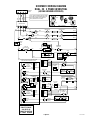
(Serial # DUAL010000 - Up)
SINGLE
®
&
SINGLE
®
SH
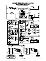
(Serial # SNG0005000 - Up)
C
A
U
TIO
N
:
WAR
M
E
R
S
AN
D
S
U
R
FA
C
E
S ARE
H
O
T
CAUTION
DISCARD DECANTER
IF:
. CRACKED
. SCRATCHED
. BOILED DRY
. HEATED WHEN EMPTY
. USED ON HIGH FLAME
. OR EXPOSED ELECTRIC
ELEMENTS
FAILURE TO COMPLY RISKS INJURY
PN: 658
1985 BUNN
-O
-MATIC CORPORATION
FUNNEL CONTENTS
ARE HOT
!
STA
RT
ON / WARMER
SELECT
OR
READY
READY
ON / WAR
MER
START
1
1⁄
2
gal
1 gal
1
⁄
2
gal
SELECTO
R
1
1
⁄
2
gal
1 gal
1
⁄
2
gal
!
CAU
T
ION
H
OT
W
A
TER
GRINDER
L
E
F
T
R
I
G
H
T
SERVICE & REPAIR MANUAL
BUNN-O-MATIC CORPORATION
POST OFFICE BOX 3227
SPRINGFIELD, ILLINOIS 62708-3227
PHONE: (217) 529-6601 FAX: (217) 529-6644
41976.0000 09/11 ©2009 Bunn-O-Matic Corporation
!
C
AUT
I
ON
:
W
AR
MER S
AND
SU
RF
ACE
S ARE
HO
T
C
AUTION
DI
S
C
A
R
D
D
E
C
AN
T
ER
I
F:
.
C
R
AC
K
ED
.
S
C
R
ATC
H
ED
.
B
O
IL
E
D
D
R
Y
.
H
E
A
T
E
D
W
H
E
N
E
M
P
T
Y
.
U
S
E
D
ON
H
I
G
H
FLA
M
E
.
O
R EX
POS
E
D
E
L
E
C
T
R
I
C
E
LE
M
EN
T
S
FA
I
LUR
E
T
O
CO
MP
L
Y
R
ISK
S
I
N
JU
RY
PN:
6
5
8
1
9
8
5
B
U
NN
-
O
-
MA
T
IC
CORPO
R
A
T
I
O
N
FUN
N
E
L
C
ON
T
EN
TS
A
R
E
H
OT
!
!
CAUT
ION
HOT
W
A
T
E
R
CAUTION
DISCAR
D
DECANTER
IF:
. C
RACKE
D
. SCR
ATCHE
D
. B
OILED
D
RY
. H
E
A
TE
D
W
H
E
N
EM
P
TY
. U
S
ED
O
N
HIGH
FLA
ME
. O
R EX
P
O
S
E
D
E
LEC
TR
IC
ELE
ME
NT
S
FAILURE
TO COM
PLY
RISKS INJUR
Y
PN
: 65
8
1
9
8
5
B
UNN
-
O-MA
TI
C CORPORA
T
ION
FUN
NEL CON
TENTS
ARE HOT
!
!
C
AU
TIO
N
H
OT WATER
CAUTION
DI
SCARD
DE
C
ANTE
R
I
F
:
.
CR
ACKED
.
SCR
A
T
CH
ED
. BOIL
ED DR
Y
. HEAT
E
D
WHEN
EM
P
T
Y
.
USED
O
N
HI
GH F
LAME
. OR EXPO
SED
ELECTR
IC
EL
E
M
ENT
S
FAI
L
UR
E
TO
COM
P
L
Y
RISKS
I
N
JURY
PN
:
6
5
8
1
9
8
5
B
U
NN
-O
-M
A
TIC
C
OR
P
O
RATION
FUNN
EL CON
TENT
S
ARE HO
T
!
!
CAUTION
HOT
WATER

Page 2
41976 050511
BUNN-O-MATIC COMMERCIAL PRODUCT WARRANTY
Bunn-O-Matic Corp. (“BUNN”) warrants equipment manufactured by it as follows:
1) All equipment other than as specified below: 2 years parts and 1 year labor.
2) Electronic circuit and/or control boards: parts and labor for 3 years.
3) Compressors on refrigeration equipment: 5 years parts and 1 year labor.
4) Grinding burrs on coffee grinding equipment to grind coffee to meet original factory screen sieve analysis:
parts and labor for 3 years or 30,000 pounds of coffee, whichever comes first.
These warranty periods run from the date of installation BUNN warrants that the equipment manufactured by
it will be commercially free of defects in material and workmanship existing at the time of manufacture and
appearing within the applicable warranty period. This warranty does not apply to any equipment, component or
part that was not manufactured by BUNN or that, in BUNN’s judgment, has been affected by misuse, neglect,
alteration, improper installation or operation, improper maintenance or repair, damage or casualty. This warranty is
conditioned on the Buyer 1) giving BUNN prompt notice of any claim to be made under this warranty by telephone
at (217) 529-6601 or by writing to Post Office Box 3227, Springfield, Illinois 62708-3227; 2) if requested by
BUNN, shipping the defective equipment prepaid to an authorized BUNN service location; and 3) receiving prior
authorization from BUNN that the defective equipment is under warranty.
THE FOREGOING WARRANTY IS EXCLUSIVE AND IS IN LIEU OF ANY OTHER WARRANTY, WRITTEN OR
ORAL, EXPRESS OR IMPLIED, INCLUDING, BUT NOT LIMITED TO, ANY IMPLIED WARRANTY OF EITHER
MERCHANTABILITY OR FITNESS FOR A PARTICULAR PURPOSE. The agents, dealers or employees of BUNN
are not authorized to make modifications to this warranty or to make additional warranties that are binding on
BUNN. Accordingly, statements by such individuals, whether oral or written, do not constitute warranties and
should not be relied upon.
If BUNN determines in its sole discretion that the equipment does not conform to the warranty, BUNN, at its
exclusive option while the equipment is under warranty, shall either 1) provide at no charge replacement parts
and/or labor (during the applicable parts and labor warranty periods specified above) to repair the defective
components, provided that this repair is done by a BUNN Authorized Service Representative; or 2) shall replace
the equipment or refund the purchase price for the equipment.
THE BUYER’S REMEDY AGAINST BUNN FOR THE BREACH OF ANY OBLIGATION ARISING OUT OF THE SALE OF
THIS EQUIPMENT, WHETHER DERIVED FROM WARRANTY OR OTHERWISE, SHALL BE LIMITED, AT BUNN’S
SOLE OPTION AS SPECIFIED HEREIN, TO REPAIR, REPLACEMENT OR REFUND.
In no event shall BUNN be liable for any other damage or loss, including, but not limited to, lost profits, lost sales,
loss of use of equipment, claims of Buyer’s customers, cost of capital, cost of down time, cost of substitute
equipment, facilities or services, or any other special, incidental or consequential damages.
392, AutoPOD, AXIOM, BrewLOGIC, BrewMETER, Brew Better Not Bitter, BrewWISE, BrewWIZARD, BUNN Espress, BUNN
Family Gourmet, BUNN Gourmet, BUNN Pour-O-Matic, BUNN, BUNN with the stylized red line, BUNNlink, Bunn-OMatic,
Bunn-O-Matic, BUNNserve, BUNNSERVE with the stylized wrench design, Cool Froth, DBC, Dr. Brew stylized Dr. design,
Dual, Easy Pour, EasyClear, EasyGard, FlavorGard, Gourmet Ice, Gourmet Juice, High Intensity, iMIX, Infusion Series,
Intellisteam, My Café, PowerLogic, Quality Beverage Equipment Worldwide, Respect Earth, Respect Earth with the styl-
ized leaf and coffee cherry design, Safety-Fresh, savemycoffee.com, Scale-Pro, Silver Series, Single, Smart Funnel, Smart
Hopper, SmartWAVE, Soft Heat, SplashGard, The Mark of Quality in Beverage Equipment Worldwide, ThermoFresh, Titan,
A Partner You Can Count On, Air Brew, Air Infusion, Beverage Bar Creator, Beverage Profit Calculator, Brew better, not
bitter., BUNNSource, Coffee At Its Best, Cyclonic Heating System, Digital Brewer Control, Nothing Brews Like a BUNN,
Pouring Profits, Signature Series, Tea At Its Best, Phase Brew, The Horizontal Red Line, trifecta, Ultra, Velocity Brew are
either trademarks or registered trademarks of Bunn-O-Matic Corporation.

Page 3
TROUBLESHOOTING
A troubleshooting guide is provided to suggest probable causes and remedies for the most likely problems
encountered. If the problem remains after exhausting the troubleshooting steps, contact the Bunn-O-Matic
Technical Service Department.
• Inspection,testing,andrepairofelectricalequipmentshouldbeperformed only by qualied
service personnel.
• Allelectroniccomponentshave120-240voltacandlowvoltagedcpotentialontheirterminals.
Shorting of terminals or the application of external voltages may result in board failure.
• Intermittentoperationofelectroniccircuitboardsisunlikely.Boardfailurewillnormallybeper-
manent. If an intermittent condition is encountered, the cause will likely be a switch contact or
a loose connection at a terminal or crimp.
• Solenoidremovalrequiresinterruptingthewatersupplytothevalve.Damagemayresultifsole-
noids are energized for more than ten minutes without a supply of water.
• Theuseoftwowrenchesisrecommendedwheneverplumbingttingsaretightenedorloosened.
This will help avoid twists and kinks in the tubing.
• Makecertainthatallplumbingconnectionsaresealedandelectricalconnectionstightandiso-
lated.
• Thisbrewerisheatedatalltimes.Keepawayfromcombustibles.
WARNING
• Exerciseextremecautionwhenservicingelectricalequipment.
• Disconnectthebrewerfromthepowersourcewhenservicing,exceptwhenelectricaltestsare
specified.
• Followrecommendedserviceprocedures.
• Replaceallprotectiveshieldsorsafetynotices.
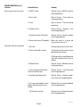
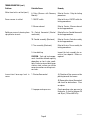
Problem
Equipment will not operate.
Brew cycle will not start.
Probable Cause
1. No power or incorrect voltage.
1. No water
2. Water strainer/flow control
(.750 GPM)
Remedy
(A1) Check the terminal block for
120 volts across the red and white
terminals and the black and white
terminals on 120V, 120/208 or
120/240 volt brewers.
(A2) Check the terminal block for 200
volts on "B Series" brewers or 240
volts on "A Series" brewers across
the red and black terminals.
(B) Check circuit breakers or fuses.
Check plumbing and shut-off
valves
(A) Direction of flow arrow must be
pointing towards brewer.
(B) Remove the strainer/flow control
and check for obstructions. Clear or
replace.
41976 031709

Page 4
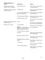
TROUBLESHOOTING (cont.)
Problem
Brew cycle will not start (cont.)
Automatic refill will not operate
Remedy
Refer to Service - ON/OFF switch for
testing procedures.
Refer to Service - Start switch for
testing procedures.
Refer to Service - Timer for testing
procedures.
Refer to Service - Dispense valve
for testing procedures.
Refer to Service - Control assembly
for testing procedures.
Make sure server is in place and
server present lamp is lit.
Check plumbing and shut-off valves.
(A) Direction of flow arrow must be
pointing towards brewer.
(B) Remove the strainer/flow control
and check for obstructions. Clear or
replace.
Refer to Service - Solenoid valve for
testing procedures.
Refer to Service - Limit thermostat
for testing procedures.
Refer to Service - Overflow protec-
tion switch for testing procedures.
Refer to Service - Level control board
for testing procedures.
Refer to Service - Electronic controls
for testing procedures.
Probable Cause
3. ON/OFF switch
4. Start switch
5. Timer
6. Dispense Valve
7. Control Assembly (Electronic)
8. Server not in place (SH models)
1. No water
2. Water strainer/flow control
3. Solenoid Valve
4. Limit thermostat (Electro/me-
chanical and Electronic)
5. Overflow protection switch
6. (A) Level control board & level
probe. (Electro/mechanical con-
trolled)
(B) Electronic controls
41976 031709

Page 5
TROUBLESHOOTING (cont.)
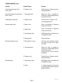
Problem
Beverage level will not adjust
(Selector switch in any position)
Water flows into tank continuously
(On/Off Switch "OFF").
Water flows into tank continuously
(ON/OFF switch "ON").
Water from tank is not hot
Probable Cause
1. Brew Selector switch
1. Solenoid valve
2A. Level control board and level
probe (Electro/mechanical)
2B. Control assembly (Electronic)
3. Overflow protection switch
1. Timer
1. Limit thermostat
CAUTION - Do not eliminate or
bypass limit thermostat. Use only
replacement part #23717.0001
2A. Control Thermostat (Electro/
mechanical)
2B. Control assembly (Electronic)
3. Contactor (Brewers with Recovery
Booster)
4. Tank heaters
5. Triac assembly (Electronic)
Remedy
Refer to Service - Selector switch
for testing procedures.
Refer to Service - Solenoid valve for
testing procedures.
Refer to Service - Level control board
for test procedures.
Refer to Service - Control assembly
for testing procedures.
Refer to Service - Timer for testing
procedures.
Refer to Service - Overflow protec-
tion switch for testing procedures.
Refer to Service -Limit thermostat
for testing procedures.
Refer to Service - Control Thermostat
for testing procedures.
Refer to Service - Control assembly
for testing procedure.
Refer to Service - Contactor for test-
ing procedures.
Refer to Service - Tank heaters for
testing procedures.
Refer to Service - Triac assembly for
testing procedures.
41976 031709

Page 6
TROUBLESHOOTING (cont.)
Problem
Water from tank is not hot (cont.).
Server warmer is not hot.
Spitting or unusual steaming from
sprayhead or airvents.
Inconsistent beverage level in
server.
Probable Cause
6. Relay (Brewers with Recovery
Booster)
1. ON/OFF switch
2. Warmer element
1A. Control thermostat (Electro/
mechanical)
1B. Control assembly (Electronic)
2. Triac assembly (Electronic)
3. Lime build-up
CAUTION - Tank and tank compo-
nents should be delimed regularly
depending on local water condi-
tions. Excessive mineral build-up on
stainless steel surfaces can initiate
corrosive reactions resulting in seri-
ous leaks.
1. Strainer/flow control
2. Improper water pressure
Remedy
Refer to Service - Relay for testing
procedures.
Refer to Service - ON/OFF switch for
testing procedures.
Refer to Service - Warmer element
for testing procedures.
Refer to Service - Control thermostat
for testing procedures.
Refer to Service - Control assembly
for testing procedures.
Refer to Service - Triac assembly for
testing procedures.
Inspect the tank assembly for ex-
cessive lime deposits. Delime as
required.
(A) Direction of flow arrow must be
pointing towards the brewer.
(B) Remove the strainer/flow control
and check for obstructions. Clear
or replace.
Check operating water pressure to
the brewer. It must be between 20
and 90 psi (138 and 620 kPa) .
41976 031709

Page 7
TROUBLESHOOTING (cont.)
Problem
Inconsistent beverage level in
server (cont.).
Consistently high or low beverage
level in server.
Dripping from sprayhead.
Water overflows filter.
Beverage overflows server.
Weak beverage.
Probable Cause
3. Dispense valve
1. Timer adjustment
1. Dispense valve
1. Bypass valve
2. Needle Valve
3. Type of paper filters
4. No sprayhead
1. Beverage left in server
2. Timer adjustment
3. Dispense valve
1. Type of paper filters
2. Coffee
Remedy
Refer to Service - Dispense valve for
testing procedures.
Adjust the timer as required to
achieve the recommended volume
for each brew cycle.
Refer to Service - Dispense valve
for testing procedures.
Refer to Installation & Operating
Guide, Initial Set-Up.
Refer to Installation & Operating
Guide, Initial Set-Up
BUNN paper filters should be used
for proper extraction.
Check sprayhead
The brew cycle should be started
only with an empty server under
the funnel.
Adjust the timer as required to
achieve the recommended volume
for each brew cycle.
Refer to Service - Timer for testing
procedures.
Refer to Service - Dispense valve for
testing procedures.
BUNN paper filters should be used
for proper extraction.
A sufficient quantity of fresh drip
or regular grind should be used for
proper extraction.
41976 031709

Page 8
TROUBLESHOOTING (cont.)
Problem
Weak beverage (cont.)
Brewer is making unusual noises.
Probable Cause
3. Sprayhead
4. Funnel loading
5. Water temperature
1. Solenoid (Inlet)
2. Plumbing lines
3. Water supply
4. Tank Heater(s)
5. Contactor
Remedy
A clean sprayhead should be used
to properly wet the bed of ground
coffee in the funnel.
The BUNN paper filter should be
centered in the funnel and the bed
of ground coffee leveled by gentle
shaking.
Empty the server, remove its cover,
and place the server on the warmer.
Place empty funnel over the server
entrance, with ON/OFF switch in the
"ON" position press the start switch
and release it. Check the water
temperature immediately below
the sprayhead with a thermometer.
The reading should not be less than
195˚F(91˚C).
The nut on back of the solenoid
must be tight or it will vibrate during
operation
Plumbing lines should not be resting
on the counter top.
(A) The brewer must be connected
to a cold water line.
(B) Water pressure to the brewer
must not be higher than 90 psi (620
kPa). Install a regulator if necessary
to lower the working pressure to ap-
proximately 50 psi (345 kPa).
Remove and clean lime off tank
heater(s).
Check for low voltage
41976 031709

Page 9
TROUBLESHOOTING (cont.)
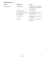
Problem
Server will not heat
Probable Cause
1. Circuit breaker
2. Receptacle Contacts
3. Relay (Server Power) (Prior to
S.N. DUAL026000)
4. Transformer
5. Rectifier
Remedy
A) Check and reset if necessary
B) Refer to Service - Circuit breaker
for test procedures.
Clean or replace.
Refer to Service - Relay (Soft Heat)
for test procedures.
Refer to Service - Transformer for
test procedures.
Refer to Service - Rectifier for test
procedures.
41976 031709

Page 10
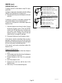
SERVICE
This section provides procedures for testing and
replacing various major components used in this
brewer should service become necessary. Refer to
Troubleshooting for assistance in determining the
cause of any problem. Illustrations shown are DUAL
brewers with SINGLE brewers similar except where
noted.
WARNING - Inspection, testing, and repair of electri-
cal equipment should be performed only by qualified
service personnel. The brewer should be unplugged
when servicing, except when electrical tests are re-
quired and the test procedure specifically states to
plug in the brewer.
COMPONENT ACCESS
WARNING - Unplug the brewer before the removal of
any panel or the replacement of any component.
All components are accessible by the removal of
the top cover, front access panel, warmer base plate
and/or server platform cover. The covers and panels
are attached with slotted head screws as follows:
SINGLE & SINGLE SH top cover (1) #4-40
DUAL & DUAL SH top cover (4) #4-40
SINGLE front access panel (4) #6-32
SINGLE SH front access panel (8) #6-32
DUAL front access panel (5) #6-32
DUAL SH front access panel (11) #6-32
SINGLE & DUAL warmer base (4) #6-32
SINGLE SH & DUAL SH server platform (4) #6-32
Contents
Brewer Selector Switch ........................................ 12
Bypass Valve ........................................................ 11
Circuit Breakers ....................................................14
Contactor Assembly ............................................. 15
Control Thermostat ..............................................17
Dispense Valve ..................................................... 18
Grinder Selector Switch .......................................20
Level Control Board and Level Probe ...................21
Limit Thermostat ..................................................23
Main Power Switch ..............................................45
ON/OFF Switch (Warmer) .....................................24
Overflow Protection Switch ..................................25
Receptacle ...........................................................26
Rectifiers ..............................................................26
Relay ....................................................................27
Solenoid ...............................................................33
Start Switches (Brew) ..........................................35
Tank Heaters ........................................................36
Timers (Early Models) .......................................... 37
Digital Timer (Late Models) ..................................40
Transformers........................................................42
Warmer Elements.................................................44
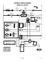
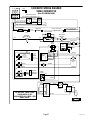
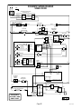
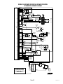
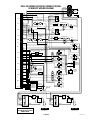
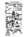
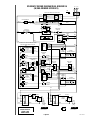
Wiring Diagrams ..................................................46
41976 031709

Page 11
SERVICE (cont.)
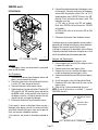
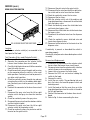
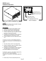
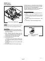
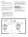
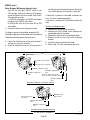
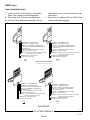
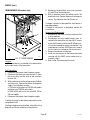
BYPASS VALVE
Location:
The bypass valves are located on the sprayhead
panel inside the hood.
Test Procedures:
1. Disconnect the brewer from the power source and
place a server beneath the funnel.
2. Check the water level in the tank to confirm that it
is within 1/2" from the top of the tank.
3. Connect the brewer to the power source.
4. Check the bypass valve for coil action. Place the ON/
OFF switch in the "ON" position, press and release
the BREW switch. Listen carefully in the vicinity of
the bypass valve for a "clicking" sound as the coil
magnet attracts and repels the plunger.
5. Disconnect the brewer from the power source.
If the sound is heard as described, there may be a
blockage in the bypass valve or the water line to the
sprayhead. Remove the bypass valve and inspect for
wear, and remove waterborne particles.
If the sound is not heard as described, proceed to
#6.
P773
P774
!
CAUTI
ON
HOT WATE
R
.
M
INUTES
BUNN-O-MATIC
P/N 2620- 120 VAC
.
MINUTES
BUNN-O-MATIC
P/N 2620- 120 VAC
1 gal
C
AU TI
ON :
WA
R
ME RS
AN
D
S
UR FA
C
ES
A
RE
H
O
T
6. Connect the voltmeter lead ends to the bypass valve
coil terminals. Connect the brewer to the power
source. With the selector switch in the 1 or 1-1/2
gallon position, place "ON/OFF" Switch in the "ON"
position. Press and release the brew switch. The
indication must be:
a.) 120 volts ac for two wire 120 volt models,
three wire 120/208 volt and three wire 120/240
volt models.
b.) 200 to 240 volts ac for two wire 200 or 240
volt models.
7. Disconnect the brewer from the power source.
If voltage is present as described, but no coil action is
observed, nor "clicking" heard, bypass valve is defective.
Replace valve and test again to verify repair.
If voltage is not present as described, refer to Wiring
Diagrams and check the brewer wiring harness. Also
check the control board for proper operation.
Removal and Replacement:
1. Remove the wires from the bypass valve.
2. Drain enough water from the tank so bypass valve
is above the water line.
3. Remove water lines from bypass valve.
4. Remove the two nuts retaining the bypass valve
inside the hood and remove bypass valve.
5. Remove hose barb fitting and attach to new bypass
valve.
6. Install new bypass valve with hose barb fitting.
7. Reconnect the water tubes and the wires to the
bypass valve.
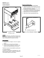
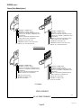
8. Refer to Fig. 2 when reconnecting the wires.
NOTE: If one of the terminals is marked "I", connect
WHI/GRN wire to it.
FIG. 1 BYPASS VALVES
WHI/GRN to Dispense
Valve
WHI/VIO to Brew
Selector Switch
FIG. 2 BYPASS VALVE TERMINALS
41976 031709

Page 12
SERVICE (cont.)
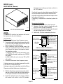
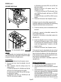
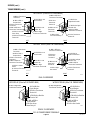
BREW SELECTOR SWITCH
Location:
The brew selector switch(es) are mounted in the
front panel of the hood.
Test Procedure (Early model Selector Switch):
1. Disconnect the brewer from the power supply.
2. Separate the connector on the selector switch
harness from the brew timer circuit board.
3. Carefully slide the plastic cover off of the connector
from the switch harness.
4. Check for continuity across the pink and tan wires
on the connector when the switch is in the small
batch position. Continuity must not be present in
any other switch position.
5. Check for continuity across the pink wire and gray
wire when the switch is in the medium batch posi-
tion. Continuity must not be present in any other
position.
6. Reattach the connector to the brew timer circuit
board.
7. Disconnect the gray wire from the left or right
selector switch and gray wire from the interface
socket.
8. Check for continuity across the gray wires.
9. Reconnect the gray wires from the selector switches
and the interface socket.
10. Disconnect the pink wire from the left or right
selector switch to the grinder switch.
11. Check for continuity across the pink wire and the
terminal on the grind switch.
12. Reconnect the pink wire to the grind switch.
13. Disconnect the tan wire from the left or right selec-
tor switch and tan wire from interface socket.
14. Check for continuity across the tan wires.
15. Reconnect the tan wires.
16. With the selector switch set at the medium and
large batch positions, disconnect the white/violet
from the bypass valve.
17. Check for continuity across the white/violet wire
and terminal on bypass valve.
18. Reconnect the white/violet wire to the terminal on
the bypass valve.
19. Disconnect the white/red wire from the dispense
valve.
20. Check for continuity across white/red wire and
terminal on dispense valve.
21. Reconnect white/red wire to the terminal on the
dispense valve.
If continuity is present as described the switch is
operating properly.
If continuity is not present as described replace switch
assembly.
Removal and Replacement:
1. Disconnect the connector on the selector switch
harness from the brewer timer circuit board.
2. Disconnect wires from the selector switch, interface
socket, dispense valve and bypass valve.
3. Loosen the set screw on the switch knob.
4. Remove the 9/16" nut and washer holding the
switch to the hood.
5. Remove the switch.
6. Install the new switch. The positioning tab must
be in the hole in the hood for proper switch and
knob alignment.
7. Install the knob so that the arrow lines up in the
large batch position when the switch is turned to
the full right position.
8. Reattach the connector to the brew timer circuit
board.
9. Refer to Fig. 4 when reconnecting the wires.
P775
START
ON / WAR
MER
SELECTOR
READY
R
EADY
ON / WAR
MER
START
1
1⁄2
ga
l1 g
al
1⁄2
gal
SELECTOR
1
1⁄2
g
al
1
g
al
1⁄2
gal
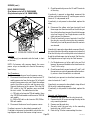
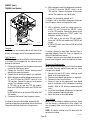
FIG. 3 BREW SELECTOR SWITCHES
41976 031709

Page 13
SERVICE (cont.)
BREW SELECTOR SWITCH (cont.)
P1388
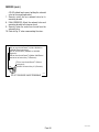
FIG. 4 BREW SELECTOR SWITCH TERMINALS
EARLY MODEL SELECTOR SWITCH
LATE MODEL SELECTOR SWITCH
Test Procedure (Late model Selector Switch):
1. Disconnect the brewer from the power supply.
2. Disconnect all wires from the brew selector
switch.
3. Check for continuity across terminals (b) and (1)
when the switch is in the small batch position.
Continuity must not be present in any other switch
position.
4. Check for continuity across terminals (b) and (2)
when the switch is in the medium batch position.
Continuity must not be present in any other posi-
tion.
TAN to Interface Socket
PNKtoInterfaceSocket
GRY to Interface Socket
WHI/RED to Dispense Valve
WHI/VIO to By-Pass Valve
To Timer
TAN
PNK
GRY
WHI/VIO to
By-Pass Valve
WHI/RED to
Dispense Valve
TAN to Grinder Interface
GRY to Grinder Interface
ORN to Timer
BLU to Timer
YEL to Timer
PNKtoGrinderInterface
b
d
4
3
2
1
e
5
5. Check for continuity across terminals (e) and (5).
When the selector switch is in the small batch
position, continuity should not be present. When
the selector switch is in the medium or large batch
positions, continuity should be present.
If continuity is present as described the switch is
operating properly.
If continuity is not present as described replace switch
assembly.
Removal and Replacement:
1. Disconnect all wires from the brew selector
switch.
2. Loosen the set screw on the switch knob.
3. Remove the 9/16" nut and washer holding the
switch to the hood.
4. Remove the switch.
5. Install the new switch. The positioning tab must
be in the hole in the hood for proper switch and
knob alignment.
6. Install the knob so that the arrow lines up in the
large batch position when the switch is turned to
the full right position.
7. Refer to Fig. 4 when reconnecting the wires.
41976 031709

Page 14
SERVICE (cont.)
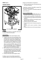
CIRCUIT BREAKERS
CAU
TIO
N
DISC
ARD DECANTER
IF
:
.
C
RA
CK
ED
.
SCR
ATCHED
.
B
OIL
ED D
RY
.
H
EA
TED
WHEN E
M
PTY
.
U
SE
D ON
H
IGH
FL
A
M
E
.
O
R
E
X
PO
S
ED
ELEC
T
RIC
ELEM
ENTS
F
AILUR
E T
O CO
MPLY RISKS I
NJURY
PN:
658
19
8
5 BUNN-O
-
MATIC
CO
RP
ORA
TIO
N
FUNNEL CO
NTE
NTS
ARE HOT
!
!
CA
U
TI
ON
HOT WA
TER
Location
The circuit breakers are located on the lower front
of the brewer, mounted on the server platform just
above the spring contact receptacle assembly.
Test Procedures:
1. Disconnect the dispenser from the power
source.
2. Remove the wires from the circuit breaker.
3. Check for continuity between the terminals. Con-
tinuity must be present between the terminals.
If continuity is present as described the circuit breaker
is functioning properly.
If continuity is not present as described, press reset
button and repeat step #3, if continuity is not present
as described, replace the circuit breaker.
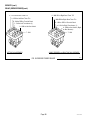
FIG.5CIRCUITBREAKERS
(SH Brewers only)
P1361
FIG.6CIRCUITBREAKERTERMINALS
P1330
BLU/BLKtoTransformer#12
BLU/BLKtoRectier"AC"
Removal and Replacement:
1. Remove the wires from the circuit breaker.
2. Compress the clips on the back side of the server
platform and gently push the circuit breaker through
the opening in the server platform.
3. Push the new circuit breaker into the opening in the
server platform until the clips snap into position.
4. Reconnect the wires to the circuit breaker.
5. Refer to Fig. 6 when reconnecting the wires.
41976 031709

Page 15
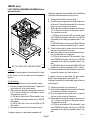
SERVICE (cont.)
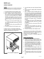
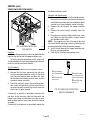
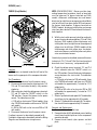
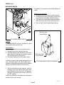
CONTACTOR ASSEMBLY
Location:
The contactor assembly is located inside the hood
just to the rear of the dispense valve (Right side for
DUAL and DUAL SH models).
Test Procedures:
Mechanical Thermostat (Brewers with or without
Recovery Booster)
1. Disconnect the brewer from the power source.
2. Disconnect the white wire of the two pole 120V ter-
minal block, white wire of the three pole 120/208V
or 120/240V or the red wire of the two pole 200V
or 240V terminal block and the black wire of the
contactor coil. Disconnect the black wire of the
control thermostat from the remaining black wire
of the contactor coil.
3. Gently remove the capillary bulb and grommet
from the tank.
4. With a voltmeter, check the voltage across the white
wire from the terminal block on 120, 120/208,
120/240 volt units or the red wire from 200 or
240 volt units and the black wire from the control
thermostat when the thermostat is turned clockwise
to the "FULL ON" position. Connect the brewer to
the power source. The indication must be:
a.) 120 volts ac for two wire 120 volt models, three
wire 120/208 volt models and three wire 120/240
volt models.
b.) 200 to 240 volts ac for two wire 200 or 240
volt models.
5. Disconnect the brewer from the power source.
If voltage is present as described, proceed to #6.
If voltage is not present as described, refer to the Wiring
Diagrams and check the brewer wiring harness.
6. Check for continuity between the two black wires
of the contactor coil.
If continuity is present as described, reconnect one
black wire to red or white wire from the terminal block
and the other black wire to the black wire from the
control thermostat. Reinstall capillary tube into the
tank to a line 7" above the bulb and proceed to #7.
If continuity is not present as described, replace the
contactor.
7. Locate the white wire or red wire on L1 terminal
and black wire on the L2 terminal on the contac-
tor.
8. With a voltmeter, carefully check the voltage across
the white or red and black wires. The indication
must be:
a.) 120 volts ac for two wire 120 volt models, 208
volts ac for three wire 120/208 volt models and
240 volts ac for three wire 120/240 volt models.
b.) 200 to 240 volts ac for two wire 200 or 240
volt models.
9. Disconnect the brewer from the power source.
If voltage is present as described, proceed to #10.
If voltage is not present as described, refer to the Wiring
Diagrams and check brewer wiring harness.
10. Check for continuity across the terminals on the
left side of the contactor by manually closing the
contacts. Continuity must not be present when the
contact is released.
11. Check for continuity across the terminals on the
right side of the contactor by manually closing the
contacts. Continuity must not be present when the
contact is released.
If continuity is present as described, the contactor is
operating properly.
P796
!
CA
UT
I
ON
HOT
W
AT
ER
.
MINUTE
S
BUNN-O-MATIC
P/N 26
20- 120 VAC
.
MINUTES
BUNN-O-MATIC
P/N 2620- 120 VAC
START
ON
/ WARMER
SELECTOR
READY
R
EAD
Y
ON / WA
RMER
START
1
1⁄2
gal1 ga
l
1⁄2
gal
SELECTOR
1
1⁄
2
g
a
l1 gal
1⁄
2
ga
l
CA U
T
I
ON :
W
AR ME R
S
AN D SU
RF AC E
S AR E
H
O
T
FIG. 7 CONTACTOR ASSEMBLY
41976 031709

Page 16
SERVICE (cont.)
CONTACTOR ASSEMBLY (cont.)
P778
If continuity is not present as described, replace the
contactor.
Test Procedures :
Electronic Control (Brewers w/Recovery Booster)
1. Disconnect the brewer from the power source.
2. Disconnect the gray wire from the black wire on
the rear of the contactor coil and white /brown wire
from the black wire on the front of the contactor
coil.
3. With a voltmeter, check the voltage across the
gray wire and white/brown wire with both "ON/
OFF" switches in the "ON" position. Connect the
brewer to the power source and press both start
switches. The indication must be:
a.) 120 volts ac for three wire 120/208 volt models
and three wire 120/240 volt models.
b.) 200 to 240 volts ac for two wire 200 or 240
volt models.
4. Disconnect the brewer from the power source.
If voltage is present as described, proceed to #5.
If voltage is not present as described, refer to the Wiring
Diagrams and check brewer wiring harness.
5. Disconnect the blue and red wires from the con-
tactor terminals. Check for continuity across the
terminals of the contactor by manually closing the
contacts. Continuity must not be present when the
contact is released.
If continuity is present as described, reconnect the
blue and red wires to the contactor terminals. Con-
nect one black lead from the contactor coil to the gray
wire and the white/brown wire to the remaining black
lead of the contactor coil. The contactor is operating
properly.
If continuity is not present as described, replace the
contactor.
Removal and Replacement:
1. Remove all wires from the contactor.
2. Remove the two #10-32 slotted head screw secur-
ing contactor to the inside of the hood.
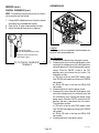
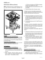
FIG. 8 CONTACTOR TERMINALS
MECHANICAL THERMOSTAT W/RECOVERY BOOSTER
ELECTRONIC CONTROL W/RECOVERY BOOSTER
BLKT2toLeftTankHeater
BLKT2toRightTankHeater
RED T1 to Left Tank Heater
RED T1 to Right Tank Heater
BLKtoBLKLeadfromThermostat
RED L1 to Terminal Block
(Red Insert)
BLKL2toTerminalBlock
(Black Insert)
BLKtoWHILeadfromthe
Three Pole 120/208V or
120/240V Terminal Block
BLKtoREDLeadfromthe
Two Pole 200V or 240V
Terminal Block
RED T1 to Terminal Block (Red
Insert)
BLU L1 to Left Tank
Heater
BLKtoGRYonRelay
BLKtoWHI/BRNtoLeft
Dispense Valve
P828
SINGLE and SINGLE SH models
WHI L1 to Terminal Block
(White Insert)
BLK T2 to Tank Heater
RED T1 to Tank Heater
RED L1 to Terminal Block
(Red Insert)
BLKL2toLimitThermostat
BLKtoBLK Leadfrom
Thermostat
BLKto WHILead fromthe Two
Pole 120V Terminal Block
BLKtoWHILeadfromtheThree
Pole 120/208V or 120/240V
Terminal Block
BLKtoREDLeadfromtheTwo
Pole 200V or 240V Terminal
Block
DUAL and DUAL SH models
3. Securely install the new contactor inside the
hood.
4. Refer to Fig. 8 when reconnecting the wires.
41976 031709

Page 17
5. Locate the black wires from the control thermo-
stat.
6. Gently remove the capillary bulb and grommet
from the tank.
7. With a voltmeter, check the voltage across the
black wires of the control thermostat and the white
insert on the two pole or three pole 120V, 120/208V,
120/240V terminal blocks and the red insert on two
pole 200V, 240V terminal blocks when the control
thermostat is turned "ON" (fully clockwise). Connect
the brewer to the power source. The indication
must be:
a.) 120 volts ac for two wire 120V models, three
wire 120/208 volt models and three wire 120/240
volt models.
b.) 200 to 240 volts ac for two wire 200 or 240
volt models.
Voltage must not be indicated across these ter-
minals when the thermostat is turned "OFF" (fully
counterclockwise).
8. Disconnect the brewer from the power source.
If voltage is present as described, reinstall the capillary
tube into the tank to the line 7" above the bulb, the
control thermostat is operating properly.
If voltage is not present as described, replace the
thermostat.
Removal and Replacement:
1. Remove wires from the control thermostat.
2. Remove the thermostat capillary bulb by firmly
pulling up on the capillary tube at the tank lid. This
will disengage the grommet from the tank lid.
3. Remove the #8-32 slotted head screw holding the
control thermostat to the component bracket.
4. Slide the grommet to the line 7" above the bulb on
the new capillary tube.
5. Insert the capillary bulb through the hole in the
tank lid and press the grommet firmly and evenly
so that the groove in the grommet fits into the tank
lid.
6. Carefully bend the capillary tube so that the tube
and bulb inside the tank are in the vertical posi-
tion.
!
CAUT
I
ON HOT WATE
R
.
M
I
N
UTES
BUN
N-O-MATIC
P/N 2620- 120 V
A
C
.
M
I
N
UTES
BUN
N-O-
MATIC
P/
N 26
20- 120 V
AC
START ON /
WARMER
S
ELECTOR
READY
R
EADY
O
N
/
WA
RMER
S
T
A
R
T
1
1⁄
2
g
al
1 ga
l
1⁄
2
g
a
l
S
E
LEC
TOR
1
1
⁄
2
g
a
l
1 ga
l
1⁄2
ga
l
CA U
T
IO
N:
W
AR ME
RS
AN
D SU R
F
A
CE S
AR E
H
O
T
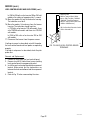
P779
Location:
The control thermostat is located inside the lower
left front of the brewer on the component bracket.
1. Disconnect the brewer from the power source.
2. Locate the blue wire on the control thermostat.
3. With a voltmeter, check the voltage across the
blue wire on the control thermostat and the white
insert on the two or three pole 120V, 120/208V,
120/240V terminal block and the red insert on
two pole 200V, 240V terminal block. Connect the
brewer to the power source. The indication must
be:
a.) 120 volts ac for two wire 120V models, three
wire 120/208 volt models and three wire 120/240
volt models.
b.) 200 to 240 volts ac for two wire 200 or 240
volt models.
4. Disconnect the brewer from the power source.
If voltage is present as described, proceed to #5.
If voltage is not present as described, refer to the Wiring
Diagrams and check brewer wiring harness.
SERVICE (cont.)
FIG. 9 CONTROL THERMOSTAT
CONTROL THERMOSTAT
41976 031709

Page 18
!
CA
UT
I
ON
HOT
W
AT
ER
.
MINUTE
S
BUNN-O-MATIC
P/N 26
20- 120 VAC
.
MINUTES
BUNN-O-MATIC
P/N 2620- 120 VAC
STA
RT
ON / WARMER
SELECTOR
READY
READ
Y
ON / WA
RMER
START
1
1⁄2
gal1 ga
l
1⁄2
gal
SELECTOR
1
1
⁄
2
g
al1 gal
1⁄
2
ga
l
CA U
T
I
ON :
W
AR ME R
S
AN D SU
RF AC E
S AR E
H
O
T
P796
Location:
Dispense valves are located inside the hood in the
center of each sprayhead panel.
Test Procedures:
1. Disconnect the brewer from the power source.
2. Disconnect the wires from the right dispense valve
and check the voltage across the white/violet wire
and white/green wire. Connect brewer to the power
source. Place the "ON/OFF" switch in the "ON"
position, press and release the start switch. The
indication must be:
a.) 120 volts ac for two wire 120V models, three
wire 120/208 volt models and three wire 120/240
volt models.
b.) 200 to 240 volts ac for two wire 200 or 240
volt models.
3. Disconnect brewer from the power source.
4. Disconnect the wires from the left dispense valve
and check voltage across the white/red wire and
the white/brown wire. Connect the brewer to the
power source. Place the "ON/OFF" switch in the "ON"
position and press and release the start switch.
The indication must be:
a.) 120 volts ac for two wire 120V models, three
wire 120/208 volt models and three wire 120/240
volt models.
b.) 200 to 240 volts ac for two wire 200 or 240
volt models.
5. Disconnect brewer from power source.
FIG. 11 DISPENSE VALVE
P780
FIG. 10 CONTROL THERMOSTAT
TERMINALS
BLU to Ready Light(s)
BLU to Overflow Protection Switch
BLKtoBLKLeadofContactorCoil
BLKtoReadyLight(s)
NOTE - The capillary tube must be clear of any electri-
cal termination and not kinked.
7. Using a #8-32 slotted head screw fasten the control
thermostat to the component bracket.
8. Refer to Fig. 10 when reconnecting the wires.
9. Adjust the control thermostat as required.
SERVICE (cont.)
CONTROL THERMOSTAT (cont.)
DISPENSE VALVE
41976 031709

Page 19
P782
DISPENSE VALVE (cont.)
SERVICE (cont.)
FIG. 12 DISPENSE VALVE TERMINALS
WHI/VIO to Right Timer TL1
WHI/VIO to Right ON/OFF Switch
WHI/RED to Right Brew Selector Switch
WHI/GRN to Right Timer TL4
WHI/GRN to Right By-Pass Valve
LEFT on DUAL Brewers
WHI/RED to Left Timer TL1
WHI/RED to Left Brew Selector Switch
WHI/RED to Left ON/OFF Switch
WHI/BRN to Left Timer TL4
WHI/GRN to Left By-Pass Valve
SINGLE Brewers & RIGHT on DUAL Brewers
If voltage is present as described in steps 2 & 4 pro-
ceed to #6.
If voltage is not present as described, refer to the Wiring
Diagrams and check brewer wiring harness.
6. Check for continuity across the dispense valve coil
terminals.
If continuity is present as described, reconnect the
wires to the dispense valve and proceed to #7
If continuity is not present as described, replace the
dispense valve.
7. Check the dispense valve for coil action. Connect
the brewer to power source. Place the ON/OFF"
switch in the "ON" position, press and release the
start switch. Listen carefully in the vicinity of the
dispense valve for a "clicking" sound as the coil
magnet attracts and repels the plunger.
8. Disconnect the brewer from the power source.
If the sound is heard as described, there may be a
blockage in the dispense valve or the water line to the
dispense valve. Remove the dispense valve and inspect
for wear, and remove waterborne particles.
If the sound is not heard as described, replace the
dispense valve.
Removal and Replacement:
1. Disconnect wires and water tubes from dispense
valve.
2. Drain enough water from the tank so the dispense
valves are above the water line.
3. Remove dispense valve from the sprayhead
panel.
4. Install new dispense valve.
5. Reconnect the water lines and the wires to the
dispense valve.
6. Refer to Fig. 12 when reconnecting wires.
41976 031709

Page 20
P787
STA
RT ON / WA
RMER
SELECTO
R
RE
A
DY
READY
O
N / WARMER
START
1
1
⁄
2
gal
1 gal
1
⁄2
gal
SELECTO
R
1
1⁄
2
ga
l
1 gal
1
⁄
2
g
al
P786
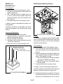
GRINDER SELECTOR SWITCH
Location:
The grinder selector switch is located in the upper
center on the front of the hood.
Test Procedure:
1. Disconnect the brewer from the power source.
2. Remove all wires from the switch terminals.
3. Place the selector switch in the left position.
4 Check for continuity across the center and right
terminals on the rear of the switch.
5. Continuity must not be present across the center
and left terminals on the rear of the switch.
6. Check the bottom row, then the top row of termi-
nals.
If continuity is present as described proceed to #7.
If continuity is not present as described replace the
switch.
7. Place the selector switch in the right position.
8. Check for continuity across the center and left
terminals on the rear of the switch.
9. Continuity must not be present across the center
and right terminals on the rear of the switch.
10. Check the bottom row, then the top row.
If continuity is present as described, reconnect the
wires, the switch is operating properly.
If continuity is not present as described, replace the
switch.
11. Refer to Fig. 14 when reconnecting the wires.
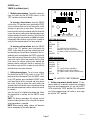
FIG. 13 GRINDER SELECTOR SWITCH
(DUAL and DUAL SH BREWERS only)
FIG. 14 GRINDER SELECTION
SWITCH TERMINALS
PNKtoPNKLeadfrom
Right Brew Selector Switch
PNKtoPNKLeadfromInterface
Socket
PNKtoPNKLeadfrom
Left Brew Selector Switch
SERVICE (cont.)
41976 031709
Page is loading ...
Page is loading ...
Page is loading ...
Page is loading ...
Page is loading ...
Page is loading ...
Page is loading ...
Page is loading ...
Page is loading ...
Page is loading ...
Page is loading ...
Page is loading ...
Page is loading ...
Page is loading ...
Page is loading ...
Page is loading ...
Page is loading ...
Page is loading ...
Page is loading ...
Page is loading ...
Page is loading ...
Page is loading ...
Page is loading ...
Page is loading ...
Page is loading ...
Page is loading ...
Page is loading ...
Page is loading ...
Page is loading ...
Page is loading ...
Page is loading ...
Page is loading ...
Page is loading ...
Page is loading ...
Page is loading ...
Page is loading ...
Page is loading ...
Page is loading ...
Page is loading ...
Page is loading ...
Page is loading ...
Page is loading ...
Page is loading ...
Page is loading ...
Page is loading ...
-
 1
1
-
 2
2
-
 3
3
-
 4
4
-
 5
5
-
 6
6
-
 7
7
-
 8
8
-
 9
9
-
 10
10
-
 11
11
-
 12
12
-
 13
13
-
 14
14
-
 15
15
-
 16
16
-
 17
17
-
 18
18
-
 19
19
-
 20
20
-
 21
21
-
 22
22
-
 23
23
-
 24
24
-
 25
25
-
 26
26
-
 27
27
-
 28
28
-
 29
29
-
 30
30
-
 31
31
-
 32
32
-
 33
33
-
 34
34
-
 35
35
-
 36
36
-
 37
37
-
 38
38
-
 39
39
-
 40
40
-
 41
41
-
 42
42
-
 43
43
-
 44
44
-
 45
45
-
 46
46
-
 47
47
-
 48
48
-
 49
49
-
 50
50
-
 51
51
-
 52
52
-
 53
53
-
 54
54
-
 55
55
-
 56
56
-
 57
57
-
 58
58
-
 59
59
-
 60
60
-
 61
61
-
 62
62
-
 63
63
-
 64
64
-
 65
65


Bunn-O-Matic Dual User manual
- Category
- Coffee makers
- Type
- User manual
Ask a question and I''ll find the answer in the document
Finding information in a document is now easier with AI
Related papers
Other documents
-
Bunn Dual® GPR 120/208V User manual
-
Broan H6HK, 15 Kw 240V,1-Phase Electric Heater Kit Product information
-
-
Broan H6HK Electric Heater Kit Product information
-
Unbranded H5HK035Q-22, 35KW, 1-Stage, 240 VAC, 3-Phase Product information
-
Broan B6BW Product information
-
-
Bunn iMIX-3S Installation & Operating Manual
-
WarmlyYours RC-40AMP Relay Product information
-