Page is loading ...

User Manual
THE STANDARD IN PRECISION MEASUREMENT
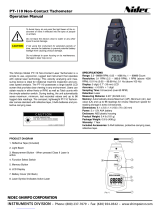
Digital Contact/Photo Tachometer
with NIST-Traceable Calibration
Model 20250-26

2

3
Introduction
The Digi-Sense Digital Contact/Photo Tachometer (Model
20250-26) is designed for quick and accurate rpm and sur-
face speed measurements. This digital tachometer is an
essential instrument in preventive maintenance programs
for ensuring the optimal performance of your equipment
and will reduce costly downtime and repairs by catching
potential equipment problems early. Easily configure the
unit for contact or noncontact measurements depending on
your application requirements. Tachometer features auto-
ranging with 0.05% accuracy; Max, Min, and last values;
built-in memory recall of last twenty average measure-
ments; and a rugged design that is ideal for industrial
environments. The instrument is fully tested and calibrated
to NIST-traceable standards. Careful use of this
meter will provide years of reliable service.
Unpacking
Check individual parts against the list of items below. If
anything is missing or damaged, please contact your
instrument supplier immediately.
1. Tachometer
2. Surface speed wheel
3. Large male rpm rubber cone
4. Small male rpm rubber cone
5. Female rpm rubber cone
6. rpm contact adapter
7. Reflective tape (23
5
⁄8", 60 cm)
8. Four set screws
9. Carrying case
10. Four AA batteries
11. User manual
12. NIST-traceable
calibration report
with data

4
Meter Description
1. Surface speed wheel
2. rpm contact adapter
3. Contact converter
4. Measure button
5. Mode/Function switch
(m/min contact, rpm
contact, rpm photo)
6. MEM button
(memory/recall)
7. Backlit LCD
8. Battery cover
6
5
7
8
4
3
2
1

5
Display Descriptions
General display function descriptions:
• “m/min” icon indicates meters per minute
• “rpm” icon indicates revolutions per minute
• “
” icon indicates low-battery status
When holding and selecting the MEM button:
• “UP” icon indicates the maximum measurement value
• “dn” icon indicates the minimum measurement value
• “LA” icon indicates the last measurement value
• “An” icon indicates memory recall of up to the last twenty
average measurement values taken
Key Features
• Microprocessor (CPU) design combines contact tachome-
ter and photo tachometer capabilities in one instrument
• Precision accuracy of ±0.05% ±1 digit
• User-configurable contact or photo capability
• Max, Min, last value, and recall of last twenty average
measurements
• Photo tachometer measures from a distance up to 19
11
⁄16"
(50 cm) away from target
• Comfortable, ergonomic design
• Durable, lightweight ABS plastic housing
• Large easy-to-read backlit display
• Low-battery indicator

6
Setup and Operation
Procedure for Contact Measurements
Rotational rpm speed measurement
1. Select the “rpm contact” option on the Mode/Func-
tion switch located on the front of the tachometer.
2. Install the contact converter to the top of the
tachometer.
3. Install the rpm contact adapter on the shaft.
4. Place desired male or female rpm rubber cone on the
rpm contact adapter.
5. Press the Measure button and lightly place the rpm
contact adapter against the center hole of the rotating
shaft. Be certain to keep alignment straight. Release
the Measure button when the display reading
stabilizes.
Surface speed measurement
1. Slide the Mode/Function switch to “m/min contact”
option.
2. Install the surface speed wheel to the shaft on the
contact converter.
3. Press the Measure button and place the surface speed
wheel on the desired surface.
4. Release the Measure button when the display reading
stabilizes.

7
Procedure for Noncontact (Photo) Measurements
1. Apply a piece of reflective tape on the object being
measured.
a. Note: Cut and peel reflective tape into approxi-
mately 0.5" (12 mm) squares and apply one
square to each rotational shaft. The nonreflective
area must always be greater than the reflective
area. If the shaft is normally reflective, it must be
covered with black tape or black paint before
attaching reflective tape. Also make sure the shaft
surface is clean and smooth before applying
reflective tape.
b. For very low rpm measurements, increase the use
of reflective tape marks and space them at equal
distances apart. Then divide the reading shown by
the number of reflective tape marks to get the
actual rpm measurement.
2. Select the “rpm photo” option on the Mode/Function
switch located on the front of the tachometer.
3. Press the side Measure button and align the visible
light beam with the applied reflective tape target.
Verify that the display indication symbol lights up
when the reflective tape target aligns with the beam.
4. Begin taking measurements

8
Displaying Maximum Measurement Value
After taking measurements, press and hold the MEM
button once. The “UP” icon will appear on the left side
of display and the maximum measurement value will be
shown on the right side of display.
Displaying Minimum Measurement Value
After taking measurements, press the MEM button two
times and hold on the second press. The “dn” icon will
appear on the left side of display and the minimum mea-
surement value will be shown on the right side of display.
Displaying Last Measurement Value
After taking measurements, press the MEM button three
times and hold on the third press. The “LA” icon will
appear on the left side of display and the last measurement
value will be shown on the right side of display.
Recalling the Stored Average Measurement Values
(up to the last 20 readings)
After taking measurements, press the MEM button four
times and hold on the fourth press. The “An” icon will
appear on the left side of display and the number of aver-
age stored measurements will be shown on the right side
of display. Every sequential press of the MEM button will
then display the individual stored number along with the
associated average value.
Note: After approximately 5 minutes of nonuse, all mea-
surement values stored in memory (maximum, minimum,
last, and stored) are erased from the tachometer.

9
Specifications
Safety
• Use extreme caution when laser beam is turned on.
• Do not let the laser beam enter your eye, another person’s
eye or the eye of an animal.
• Be careful not to let the laser
beam on a reflective surface
strike your eye.
• Do not allow the laser light
beam to impinge on any gas
which can explode.
Mode/
Function
Contact Photo
Range 0.5 to 19,999 rpm 2.5 to 99,999 rpm
Resolution
0.1 rpm from 0.5 to 999.9 rpm;
1 rpm over 1000 rpm
0.1 rpm from 2.5 to 999.9 rpm;
1 rpm over 1000 rpm
Accuracy ±(0.05% + 1 digit)
Surface speed 0.2 to 6561 ft/min; 0.05 to 1999.9 m/min
Sampling time 0.8 second (over 60 rpm)
Range select Auto-range
Time base Quartz crystal
Detecting
distance
— 50 to 500 mm
Display Backlit 5-digit LCD
Weight 8.6 oz (244 g)
Dimensions 8
1
⁄4" x 2
7
⁄8" x 1
1
⁄2" (21 x 7.4 x 3.7 cm)
Power Four AA batteries

10
Maintenance, Recalibration, and Repair
Cleaning and Storage
• Meter should be cleaned with a damp cloth and mild
detergent when necessary. Do not use solvents or abrasives.
• Store the meter in an area with moderate temperature and
humidity.
Battery Replacement
When the battery power falls low, the low-battery icon will
appear on the screen. Replace the four AA batteries in the rear
battery compartment by removing the battery door. Ensure
that the cover is securely refastened when finished. Remove
batteries if unit is not being used for extended time periods.
Note: Install batteries aligning the positive and negative ends
with the “+” and “-“ symbols located on the battery floor
compartment. Installing the batteries incorrectly may cause
permanent circuit damage to the tachometer.
It is recommended that Digi-Sense products are calibrated
annually to ensure proper function and accurate measure-
ments; however, your quality system or regulatory body may
require more frequent calibrations. To schedule your recalibra-
tion, please contact InnoCal, an ISO 17025 calibration
laboratory accredited by A2LA.
Phone: 1-866-INNOCAL (1-866-466-6225)
Fax: 1-847-327-2993
E-mail: [email protected]
Web: InnoCalSolutions.com

11

For Product and Ordering Information, Contact:
Manual Part No. 00100-48
1065DGMAN_20250-26 Rev.1
sales@novatech-usa.com
www.novatech-usa.com
Tel: (866) 433-6682 Fax: (866) 433-6684
Tel: (281) 359-8538 Fax: (281) 359-0084
/