13
4- MAIN CHARACTERISTICS
DESCRIPTION OF EQUIPMENT
This handbook concerns various equipment
models.
For further information regarding your model,
please refer to the "Technical Data" table.
_Range of single or double-opening ambient and
hot cupboard counters with sliding or leaf doors.
_Range of equipped cupboard counters with
sliding or leaf doors.
_Range of sinks with sliding-door cupboards.
_Range of sinks with sliding or leaf-door
cupboards for inserting a dishwasher.
_Range of sliding-door crockery storage cabinets.
Information on noise levels:
The functional components of the equipment in
question have a noise level not exceeding 70
dB(A).
TECHNICAL CHARACTERISTICS
The declared max. load capacity of the equipment
is 100kg per shelf.
Power supply 220-240/1/50-60Hz.
Consumption 2.4 kW.
The “hot” units come with telethermostat preset to
50°C with a worktemperature range 50°C
÷60°C.
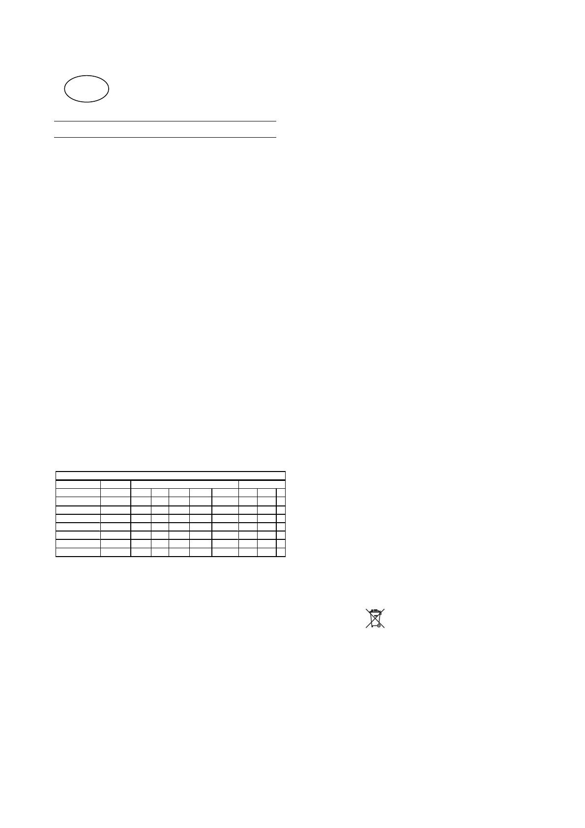
HOT CUPBOARD TYPE
TEMP. OFFSET
Dimensions
pre-adjust 50°c 60 min. 90 min. 120 min. 150 min. 180 min. shelf bottom total
(mm.)
range (°c) 1 H 1,5 H 2 H 2,5 H 3 H Ø235 mm. Ø255 mm. n.
L1000xP700xH850-900 50-60
32-36 37-43 41-49 44-53 46-56 96 102 198
L1200xP700xH850-900 50-60
31-35 36-42 40-48 43-52 45-55 128 136 264
L1400xP700xH850-900
50-60
30-34 35-41 39-47 42-51 44-54 160 136 296
L1600xP700xH850-900
50-60
29-33 34-40 38-46 42-50 44-53 160 170 330
L1800xP700xH850-900
50-60
28-32 33-39 37-45 41-49 43-52 192 204 396
L2000xP700xH850-900
50-60
27-31 32-38 36-44 40-48 42-51 224 238 462
TEMPERATURE OF DISH (T "average" = °c with maximum load) NUMBER OF DISH (approx.)
PERFORMANCE HOT CUPBOARD
EQUIPMENT IDENTIFICATION
The equipment model is given in the PNC field on
the "Technical Data" plate located on the inside of
the cupboard.
GENERAL INSTRUCTIONS
Before installing and starting the equipment,
carefully read this handbook as it provides
important information and instructions on safe
installation, use and maintenance.
Carefully keep this handbook for further
consultation by the various operators, or in case
the equipment is resold.
Important:
Equipment installation and any maintenance
work or adaptation must only be carried out by
professionally qualified personnel authorised
by the Manufacturer.
This equipment is intended for specific industrial
use; any other type of use is deemed improper.
It must only be used by trained personnel.
Always switch the equipment off in case of a fault
or poor operation.
For any repairs, contact only a technical
assistance centre authorised by the
manufacturer and demand original
replacement parts.
Failure to observe the above can compromise
the equipment's safety and invalidates any
form of warranty.
Do not wash the equipment with direct jets of
water.
Do not use products containing chlorine (sodium
hypochlorite, hydrochloric acid, etc.), even if
diluted, to clean the steel.
Do not use corrosive substances (e.g. muriatic
acid) to clean the floor under the equipment.
The manufacturer declines any liability for
operations carried out on the equipment
without following the instructions given in the
manual.
No part of this manual can be reproduced.
WASTE DISPOSAL AND SCRAPPING
At the end of the product's working life, make sure
it is not dispersed in the environment.
Special waste can be stored temporarily awaiting
disposal by treatment and/or permanent storage.
In any case, the current environmental protection
laws in the country of use must be observed.
Different regulations are in force in the various
countries, therefore the provisions of the laws and
competent bodies in the countries where
demolition takes place must be observed.
In general, the equipment must be taken to a
specialised collection/demolition centre.
Dismantle the equipment, grouping the parts
according to their chemical characteristics,
remembering that some can be recovered and
reused and that in any case it concerns waste
assimilable with urban waste.
Make the equipment unusable before disposal,
removing the power cable and any compartment
closing device, to prevent the possibility of
someone becoming trapped inside.
The symbol
“WEEE” on the product
indicates that it should not be considered as
domestic waste, but must be correctly disposed of
in order to prevent any negative consequences for
the environment and the health of people.
For further information regarding the recycling of
this product, contact the agent or local dealer, the
after-sales service or the local body responsible
for waste disposal.
Dismantling operations must be carried out by
qualified personnel.
EN


