Page is loading ...

OM-CC40-E
OPERATOR MANUAL
MODEL: CC40-E
Combo SuperSystem 40™
Combination Steamer-Oven
THIS MANUAL MUST BE RETAINED FOR FUTURE REFERENCE. READ,
UNDERSTAND AND FOLLOW THE INSTRUCTIONS AND WARNINGS
CONTAINED IN THIS MANUAL.
FOR YOUR SAFETY
DO NOT STORE OR USE GASOLINE OR OTHER FLAMMABLE
VAPORS AND LIQUIDS IN THE VICINITY THIS OF ANY OTHER
APPLIANCE.

Table of Contents
OPERATOR WARNINGS..........................................................................1
EQUIPMENT DESCRIPTION................................................................. 2, 3
WATER CONDITIONING...........................................................................4
INSTALLATION.............................................................................5, 6, 7, 8
INITIAL START-UP ...................................................................................9
OPERATION....................................... 10, 11, 12, 13, 14, 15, 16, 17, 18, 19
CLEANING & MAINTENANCE
CLEANING................................................................20, 21, 22, 23, 24
MAINTENANCE.............................................................................. 25
DIAGRAMS & SCHEMATICS ............................................................26, 27
TROUBLESHOOTING............................................................................. 28
TROUBLESHOOTING GUIDE................................................................. 29
REFERENCES....................................................................................... 30
SERVICE LOG ....................................................................................... 31
NOTES................................................................................................... 32
WARRANTY........................................................................................... 33

IMPORTANT READ FIRST IMPORTANT
WARNING: BE SURE ALL OPERATORS READ, UNDERSTAND, AND FOLLOW THE
OPERATING INSTRUCTIONS, CAUTIONS, AND SAFETY INSTRUCTIONS
CONTAINED IN THIS MANUAL.
DANGER: ELECTRICALLY GROUND THE UNIT AT THE TERMINAL PROVIDED. FAILURE TO
GROUND THE UNIT COULD RESULT IN ELECTROCUTION AND DEATH.
WARNING: THE UNIT MUST BE INSTALLED BY PERSONNEL QUALIFIED TO WORK WITH
ELECTRICITY AND PLUMBING. IMPROPER INSTALLATION CAN CAUSE INJURY
TO PERSONNEL AND/OR DAMAGE TO THE EQUIPMENT. THE UNIT MUST BE
INSTALLED IN ACCORDANCE WITH ALL APPLICABLE CODES.
WARNING: STEAM CAN CAUSE BURNS. AVOID ESCAPING STEAM WHEN OPENING DOOR.
WARNING: STAY AWAY FROM HOT AIR THAT COMES OUT AS DOOR IS OPENED.
WARNING: DO NOT PUT HANDS OR OTHER OBJECTS INTO THE COOKING CHAMBER
DURING FAST COOL OPERATION. ROTATING FAN CAN BE HAZARDOUS.
WARNING: BEFORE CLEANING THE OUTSIDE OF THE UNIT OR REMOVING ANY PARTITION
OR PANEL, ALWAYS SWITCH OFF THE ELECTRIC POWER. BEFORE WORKING
ON ANY ELECTRICAL COMPONENT, DISCONNECT THE POWER SOURCE FROM
THE UNIT.
WARNING: KEEP WATER AND SOLUTIONS OUT OF ALL CONTROLS AND ELECTRICAL
COMPONENTS. NEVER HOSE OR STEAM CLEAN ANY PART OF THE UNIT.
WARNING: DO NOT TRY TO CLEAN THE COOKING CHAMBER WHILE IT IS HOT FROM
OPERATION IN THE OVEN OR COMBO MODE. SEE THE FAST COOL
INSTRUCTIONS IN THE OPERATION SECTION OF THIS MANUAL.
WARNING: DO NOT MIX DE-LIMING AGENT (ACID) AND DEGREASER (ALKALI) IN THE
STEAM GENERATOR OR ON THE COOKING CHAMBER WALLS. REFER TO
MANUFACTURERS INSTRUCTIONS.
WARNING: BEFORE YOU REACH INTO THE OVEN TO REMOVE PARTITIONS, EXIT THE FAST
COOL MODE AND SWITCH OFF THE POWER. DO NOT REACH IN THE OVEN
UNTIL THE FANS HAVE STOPPED MOVING.
WARNING: AVOID ALL DIRECT CONTACT WITH HOT EQUIPMENT SURFACES. DIRECT SKIN
CONTACT COULD RESULT IN SEVERE BURNS.
CAUTION: TAKE PRECAUTIONS TO AVOID CONTACT WITH ANY CLEANER, DE-LIMING
AGENT, OR DEGREASER, AS RECOMMENDED BY THE SUPPLIER. MANY
CLEANERS ARE HARMFUL TO THE SKIN, EYES, MUCOUS MEMBRANES, AND
CLOTHING. CAREFULLY READ THE WARNINGS AND FOLLOW THE DIRECTIONS
ON THE LABEL OF THE CLEANING AGENT.
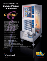
1

Electric Combo SuperSystem 40
Pan Rack
Transport Cart With Pan Rack Locked
In Place For Loading Etc.
Combo SuperSystem 40 With Cart And
Rack In Loading Position
2
Transport Cart

Equipment Description
The Groen Convection Combo™ consists of a stainless steel cooking chamber, an air heating
compartment with electric heating elements and dual fans, a steam generator with electric heating
elements, and a control compartment housing electrical components.
All major components of the Convection Combo are encased in a 16 gauge stainless steel cabinet. Glass
fiber insulation, 1 to 2 inches thick, lines the cabinet.
The oven has a double door with two large, tempered glass windows in each door. Oven viewing lights are
mounted between the inner and outer doors. Separate hinges allow easy access to the space between the
doors for window cleaning and light fixture maintenance. A condensate collection tray at the bottom diverts
condensate to the oven drain. An optional solid door is available. The solid door does not provide viewing
lights.
All operator controls are on the front panel. Standard controls permit the Convection Combo to operate in
four modes:
1. As a convection oven
2. As a self-contained, pressureless steamer
3. As a combination oven-steamer
4. With the meat probe operating
Cooking chamber capacity:
28 Steam table pans (12 x 20 x 2-1/2"), or 20
Bake pans (18 x 26"), or 40 Gastronorm pans
(1/1)
All units are supplied on stainless steel legs.
Controls and monitoring displays for cooking time, operating mode, and temperature occupy the control
panel. The upper portion of the panel has a digital time readout and touch pads for setting the time. Below
the timer section are lights to indicate the status of the unit plus touch pads that select the mode of
operation and switch on the power. A digital readout shows the chosen temperature, which is selected with
a dial. Status of the pilot burners is indicated by the lights above the pilot ignition switch, located behind the
sliding door in the front of the unit.
An insulated steam generator is mounted next to the oven. Steam enters the cooking chamber through two
connecting tubes at the top and bottom on the right side of the cavity.
The air heating space, containing the heat exchanger tubes and fans, is separated from the cooking
chamber by removable right-hand and top partitions.
The compartment containing the automatic controls and other electrical components is on the right-hand
side of the unit and is entered by removing the right outside panel or by opening the hinged panel in the
front.
A drain is located in the floor of the cooking chamber. Fluids drain from the floor to the stainless steel drain
pipe outside the oven. This drain pipe includes a spray condenser, which suppresses any steam escaping
from the chamber. The drain assembly includes a built in vent with overflow protection.
The roll-in loading and unloading equipment for Combo SuperSystem 40 consists of the Model CCS "Smart
Cart" and the separate Model CRS rack. When the rack is engaged with the cart, a hand crank raises the
rack for transportation and lowers the rack to position it in the oven. The cart is disengaged from the rack and
removed before the oven door is closed. Design of the system allows the rack to be easily held in and
transferred between reach-in or walk-in refrigerators and freezers, blast chillers, and holding cabinets.
3

Water Conditioning
It is desirable to supply the steamer with water that will not form scale. Scale formation depends on the hardness of
the water and the hours of operation. In a few areas of the United States, the water supply is sufficiently free of
minerals to avoid scale formation. However, most water supplies carry heavy loads of minerals, which will form scale
and possibly cause premature failure of components.
Your local water utility can provide a statement on the scale forming qualities of the water supply. Water
supplied to the boiler should contain not more than 30 parts per million total dissolved solids (TDS) and
should have a pH of 7.0 or higher.
Please follow these simple precautions:
1. Do not rely on "water treaters" commonly sold as scale preventers and scale removers. They do not
work. The only proven way to prevent scale build-up is to feed in water practically free of scale-forming
minerals.
2. If your water supply carries scale-forming minerals, as most water supplies do, run the water through a
properly maintained softener. Exchangeable softener cartridges or a regeneratable softener can be
used. In either case, establish a regular program of exchanging the cartridges or regenerating the
softener. Installing a water meter on the inlet line between the softener and the steamer will give an
accurate check of water consumption and a way of determining when to change the cartridge or
regenerate the softener. By using a softener and operating within the softener's capacity to exchange
minerals, the user will optimize performance and minimize maintenance of the steamer.
3. If you notice a slowing of steam production, have your authorized Groen service representative check
the unit for build-up of scale. Heavy scale will reduce the unit's ability to boil water and can cause a fire
tube in the steam generator to overheat and burn out.
TO MINIMIZE SCALE PROBLEMS, USE AND PROPERLY MAINTAIN A SOFTENER, AND CLEAN
THE STEAM GENERATOR PERIODICALLY OR AS NEEDED.
4

Installation
A. Mounting
Do not install a unit in these locations:
• Where the right side vents are blocked or within 6 inches (15 cm) of any
combustible material or within 12 inches (31 cm) of a heat source, like a
braising pan, deep fryer, char broiler, or kettle.
• To the left of any open-flame equipment.
• With less than 7 inches (18 cm) of clearance at the rear.
To avoid drainage problems, level the unit front-to-rear, or provide a slight pitch to the rear. Maintain a
minimum 8-1/2 inch (22 cm) clearance between the cabinet and the floor (Figure 2), to permit proper
operation of the cart.
WARNING:
THE UNIT MUST BE INSTALLED
BY PERSONNEL QUALIFIED TO
WORK WITH ELECTRICITY AND
PLUMBING. IMPROPER
INSTALLATION CAN CAUSE
INJURY
TO PERSONNEL AND/OR
DAMAGE TO THE EQUIPMENT.
THE UNIT MUST BE INSTALLED IN
ACCORDANCE WITH ALL
APPLICABLE CODES.
B. Electrical Supply Connection
Local codes and/or the National Electrical Code should be
observed in accordance with ANSI/ NFPA 70-1987 (or latest
edition). AN ELECTRICAL GROUND IS REQUIRED. The
electrical schematic is located in the service compartment
and in this manual. In Canada, provide electrical service in
accordance with the Canadian Electrical Code, CSA C22.1
Part 1, and/or local codes.
DANGER:
ELECTRICALLY GROUND THE UNIT AT THE TERMINAL PROVIDED.
FAILURE TO GROUND THE UNIT COULD RESULT IN ELECTROCUTION
AND DEATH.
1. Panel Removal
The wiring and the control compartment are accessed by removing the right side panel. Remove
one screw at the back of the panel, then slide the panel toward the front of the unit. Set the panel
aside.
2. Supply Voltage
The CC40-E must operate at the rated nameplate voltage ±10%.
3. Terminal Block
The terminal block for incoming power is located at the back of the control compartment. The
ground terminal is located below the terminal block. The unit must have a separate ground wire
for safe operation. Minimum size of the ground wire is 6 AWG (4.5 mm) for a 200 Amp circuit or 8
AWG (3.5 mm) for a 100 Amp breaker.
5
NOTICE:

Installation (cont'd)
4. Supply Wire
To determine the type of wire needed for the power supply, find the operating voltage from the
back data plate. Refer to the "Electrical Supply Connection" label on the back of the unit for
correct wire size and insulation temperature rating.
The specified wire must be used to meet Underwriters Laboratories and National Electrical Code
requirements.
The knockout hole (Figure 3) is sized for a 2 inch (51 mm) conduit fitting.
CC40-E ELECTRICAL SUPPLY CONNECTION
(All wires are copper only. Reference:
National Electrical Code.)
Voltage Size for 75°C (THWN) Size for 90°C (THHN)
208
N/A
2/0 AWG (10 mm)
240
N/A
1/0 AWG (9 mm)
480 #3 AWG (6 mm) #4 AWG (6 mm)
5. Branch Circuit Protection
It is strongly recommended that each Convection Combo have its own branch circuit protection.
CC40-E CURRENT DEMAND
Voltage Maximum Current per Line
(3
Phase)
Maximum Power
208 155 A 56 KW
240 135 A 56 KW
480 67 A 56 KW
Each current-carrying conductor must have overcurrent protection. Refer to the label on the rear
of the unit for proper wire size and type. Watertight connections to the unit are required.
6

Convection Combo Utility Connections
7

Installation (cont'd)
C. Water Supply Connection
Two water connections are required. One supplies water to the steam generator (treated water), and the
other is for the condensate spray (untreated water). A back siphonage device (check valve) must be
installed in each incoming cold water line according to local plumbing code. The water line pressure
should be between 30 and 60 PSIG (210 and 410 kPa). A pressure regulator is required above 60 PSIG
(410 kPa). Two 3/4 inch NH (garden hose type) connectors are required to connect the water supply to
the water inlet valves. The minimum diameter of each water feed line is 1/2 inch (13 mm). Use a washer
(or, if necessary, two washers) in the hose connection. Do not allow the connection to have any leak,
regardless of how small.
D. Drain Connection
A hose may be attached to the outlet of the drain by means of a clamp. Use 3" ID hose for CC40-E. The
hose may be connected directly to an atmospherically vented building drain.
The drain has a 2 inch (5 cm) air vent, which eliminates the need for a free air gap at the connection to the
building drain, unless such a gap (Figure 4) is required by local code. Do not block the air vent in any way.
Do not attach anything to the vent tube or reduce the size of the vent tube.
Do NOT use plastic pipe in the drain line, because the drain must withstand boiling water. Install the drain
line with a constant downward pitch. Do NOT create any water trap (Figure 5) in the line.
Proper Drain Line Connection
Figure 4
Improper Drain Line Connection
Figure 5
8

Initial Start-Up
After the Combo SuperSystem has been installed, perform initial testing to ensure that the unit is operating
correctly.
1. Remove all literature and packing materials from the interior and exterior of the unit.
2. Make sure both cold water supply lines are open and none of the fittings is leaking.
3. Turn on electrical service to the unit.
4. High altitude operation. The altitude of operation can be programmed into the Convection Combo. At
altitudes above 2,000 feet, the unit will not operate in Steamer or Combo Mode unless the altitude is
set. To set the altitude:
a. If the unit is on, turn it off by pressing the ON touch pad.
b. Press and hold the STEAM touch pad while turning the unit on by pressing the ON touch pad. The
timer display will show the letters AL and a number that represents the altitude in thousands of feet. If
the altitude has never been set on your unit, the number displayed will be 1.
c. Enter the proper altitude value, between 1 and 15, using the numbered touch pads. For example, if
the unit will be used at an altitude of 7,000 feet, press the 7 touch pad.
d. Press the START touch pad.
5. To test Steamer Mode operation, turn on the unit. (For details of operating procedure, see the
Operation section of this manual.) Clear any time from the time display, close the door, and press the
STEAM touch pad. (If the HOT light is on, see the Fast Cool instructions in the Operation section.) The
WAIT light will stay on while the steam generator fills with water and heats the water. Within 15 minutes
the WAIT light should go off and the READY light should come on, indicating that the water has reached
the standby temperature. The timer controls operation (in Steamer Mode only), so enter a time, then
push START. The colon on the time display will blink, and the generator will begin to produce steam.
The timer will not count down, if the READY light is not lit.
WARNING: STEAM CAN CAUSE BURNS. AVOID ESCAPING STEAM WHEN OENING
DOOR.
IMPORTANT: You cannot change modes if the timer is running.
6. To test Combo Mode operation, turn the power on and clear any time from the timer display, Press
the COMBO touch pad. Set the COOK temperature to 300 F (150°C). The WAIT light will come on and
stay on, while (1) the steam generator fills with water and heats the water to standby temperature and
(2) the air heater raises air temperature to 300°F. Both actions should be completed in about 15
minutes, starting with a cold unit. Then the WAIT light will go off and the READY light will come on.
WARNING: STEAM CAN CAUSE BURNS. AVOID ESCAPING STEAM WHEN OENING
DOOR.
IMPORTANT: The timer does not control the oven in Combo Mode or Oven Mode.
7. To test Oven Mode operation, turn the power on and clear any time from the timer display. Press the
OVEN touch pad. Set the COOK temperature to 350°F (175°C). The WAIT light will come on. Within 10
minutes from a cold start, the WAIT light should go off and the READY light should come on. When that
happens, turn the COOK temperature setting down to 300°F (150°C). The HOT light will come on.
8. To test Meat Probe operation, turn the PROBE knob clockwise to activate the probe. Confirm that the
temperature shown in the TIME display is the actual temperature of the probe. Then turn the PROBE
knob counterclockwise to inactivate the probe.
9. To shut down the unit, first clear the timer. Then press the mode touch pad for the mode the unit is in.
Switch off the power.
10. If the Convection Combo behaves as described, the unit is functioning correctly and ready for use.
9


WARNING: BE SURE ALL OPERATORS READ,
UNDERSTAND, AND FOLLOW THE
OPERATING INSTRUCTIONS, CAUTIONS,
AND SAFETY INSTRUCTIONS CONTAINED
IN THIS MANUAL.
DO NOT OPERATE THE UNIT IN ANY
MODE, UNLESS ALL INTERIOR
PARTITIONS HAVE BEEN RETURNED TO
THEIR PROPER LOCATIONS.
NOTE: Before the control panel can be operated as
described in this Operation section, the pilot burner flame
must be established. See the Initial Start-Up section for
details.
A. Controls and Indicators
The control features routinely used by the operator are on
the right front side of the unit and are described as follows.
(Refer to Figure 7).
1. Time Section
In the Oven and Combo Modes of operation, the timer
functions only as a "cooking time minute minder" and
does not turn the unit on or off. In the Steamer Mode, the
timer controls the operation of the steaming function.
a. Display Window — Displays the operating time
remaining in the Steamer, Oven, or Combo Mode,
because the timer counts down. Format of the
display is "hours : minutes". Maximum minute
display accepted by the unit is 59. Any recipe
calling for more than 59 minutes should be
converted to hours and minutes format, e.g., 90
minutes is equal to 1 hour and 30 minutes. Display
will read 01:30.
b. Time touch pads — used to enter time values.
c. CLEAR — Pressing this touch pad once stops the
beeper and resets the timer to the timer that was
last set. Pressing twice clears the timer to 00:00.
(At the end of a cooking period, opening the door
has the same effect as pressing CLEAR once.)
d. START— Pressing this touch pad will start the timer
and, if the unit is in Steamer Mode, also cause
steaming to begin.
2. Status Lights
a. HOT— Indicates the chamber temperature is
more than 15°F (8°C) above the cook temperature
setting (see item 5 in this section).
11

Operation (cont'd)
b. SERVICE — Indicates a problem that may require
a service call. If such a problem has occurred, the
beeper will sound and the SERVICE light will be
on, when power is switched on. The unit may
continue to operate, depending on the type of
problem. Refer to the Troubleshooting section to
determine the nature of the problem.
c. WAIT— Indicates the unit is either heating or
cooling toward the set temperature. The HOT and
WAIT lights will be on together, if the chamber is
more than 15°F (8°C) above the set point.
d. READY — Indicates the unit is ready for use.
3. Cooking Mode Selection
These touch pads are used to select the mode of
operation. If a mode is off, pressing the pad for that
mode will switch the mode on. If the mode is on,
pressing its pad will switch the mode off. A light just
above each pad shows which mode has been selected.
a. STEAM — Selects steamer operation.
b. COMBO—Selects combined steam and
convection oven operation.
c. OVEN — Selects operation of the convection
oven only.
4. Power
This touch pad is used to switch the unit on or off.
When power is on, the ON light just above the pad is lit
Use of this pad does not reset the controls, so the unit
will come on in the same mode it was in when it was
last switched off.
5. TEMP Section
a. The window displays the selected temperature in
either Oven or Combo Mode. It is blank in the
Steamer Mode.
b. Turning the knob selects the cooking temperature in
5°F increments. The control ranges are:
Oven Mode 200 to 500°P (95 to 260°C) Combo
Mode 220 to 500 F (105 to 260
0
C)
6. Meat Probe Selection
This rotating knob is used to turn on or off the hold function. By selecting a certain temperature
(ranging between 80°F and 200°F) the food can be maintained at a constant temperature for a fixed
amount of time.
7. Door Lights Selection
Door lights can be turned on/off to view the food inside by using this touch pad. These lights are not
available with the optional solid door.
12

B. Operating Instructions
1. Steamer Mode
a. If the unit is off, switch on the electric power by
pushing the ON touch pad. (If the SERVICE
indicator lights when power is switched on, see
the Troubleshooting section.)
b. If power is already on and any number is showing
in the time display window, press the CLEAR
touch pad one or more times to reset the time
display to zero.
IMPORTANT: You cannot change mode while
the timer is running.
c. The unit will be in the mode of operation that was
used last, so the indicator for that mode will be lit.
If the unit is not already in Steamer Mode, press
the STEAM touch pad. The STEAM indicator will
light, and the TEMP window will go blank.
d. If the unit has just been used in Oven or Combo
Mode, lighting of the HOT indicator may show that
the cooking chamber is too hot for use as a
steamer. The unit can be cooled quickly to the
proper temperature range for steaming by leaving
the door open or by following the Fast Cool
procedure described near the end of this section.
While the door is open, the generator can fill and
heat water to 200°F, but it cannot produce steam.
e. The WAIT indicator will be lit until the water
reaches approximately 200°F (93°C). Then the
WAIT light will go off and the READY indicator will
light. You are now ready to steam foods in your
Convection Combo.
f. Load the food into the pan or pans so there is a
uniform layer.
g. Place the pans in the rack, which is on the cart. If
there are only a few pans, uniformly distribute them in
the center of the rack.
h. Press the numbered touch pads to set the cooking
time. The time set will appear in the time display
window. If you enter the wrong number, press the
CLEAR pad to erase the time from the display, then
set the time again.
i. Carefully open the door, then move the cart so the
rack goes into the oven cavity. Using the hand crank
lower the rack to the floor of the cavity. Remove the
cart and close the door.
13

Operation (cont'd)
j. When the correct cooking time has been entered,
press the START pad. The colon will blink, and the
timer will count down the cooking time. (The unit
must be READY before the timer can count down.)
k. Opening the door during the cooking period stops
the production of steam and interrupts (but does
not reset) the timer. Closing the door allows
steaming and timing to continue.
I. When the timer has counted down to zero, it will
stop the generation of steam and sound a beeper
alarm. Water in the steam generator will be held at
the standby temperature (about 200°F or 93°C).
The beeper will continue until the door is opened or
the CLEAR pad is pressed.
m. Carefully open the door. If the food is cooked,
engage the cart with the rack, then crank the rack
up, and remove the rack from the oven.
n. After the timer display has counted down to zero,
opening the door or pressing CLEAR once will
reset the display to the time that was used last.
Pressing START will repeat the cook cycle. If the
same cooking time will be used repeatedly, you
need to press the number keys only when you first
use that time.
o. After the timer display has counted down to zero,
the timer can be reset to zero by either (1) opening
the door and pressing CLEAR or (2) pressing
CLEAR twice. A new cooking time must be set by
using the number keys.
2. Oven Mode
a. To use the Convection Combo as a convection
oven, first switch on the electric power by pushing
the ON touch pad. (If the SERVICE indicator lights
when the power is switched on, see the
Troubleshooting section.) The fan will begin to
operate, if the door is closed and the cooking
chamber temperature is above 200°F.
b. If power is already on and any number is showing in
the time display window, press the CLEAR touch
pad to erase the time display.
IMPORTANT: You cannot change mode while
the timer is running.
c. The unit will be in the mode of operation that was
used last, so the indicator for that mode will light. If
the unit is not already in Oven Mode, press the
OVEN touch pad. The OVEN indicator will light,
and the oven fan will operate.
14
WARNING: STEAM CAN CAUSE BURNS,
AVOID ESCAPING STEAM
WHEN OPENING DOOR

D. Using the dial in the TEMP section of the control
panel, set the desired cooking temperature, which
will appear in the temperature display window
beside the dial. Unless the cooking chamber is
already at or above the set temperature, the unit
will begin heating the chamber, and the WAIT —-
indicator will light.
e. If the unit has just been used at a temperature
more than 15°F (8°C) higher than the desired
temperature, the HOT and WAIT indicators will
light. The unit can be cooled quickly to the correct
temperature by leaving the door open or by
following the Fast Cool procedure near the end of
this section.
f. The READY light will indicate when the oven is at
the desired temperature.
g. Load the food into the pan or pans so there is a
uniform layer.
h. Place the pans in the rack. which is on the cart. If
there are only few pans, uniformly distribute them
in the center of the rack.
i. The Convection Combo will operate in Oven Mode
with the timer either on or off. If you wish to time the
cooking, press the numbered pads at the TIME
portion of the control panel to set the cooking time.
The time set will appear in the time display window.
If you enter the wrong number, press the CLEAR
touch pad twice to erase the time from the display,
then set the time again. Remember that the timer
does not control the unit in Oven Mode.
WARNING:STAY AWAY FROM HOT AIR THAT
COMES OUT AS DOOR IS OPENED.
j. Carefully open the cooking chamber door. Push the
cart so the rack goes into the oven cavity. Using
the hand crank, lower the rack to the floor of the
cavity. Remove the cart and close the door.
k. If cooking time has been set on the timer,
immediately press the START touch pad. Timing
will begin, and the time shown in the display will
decrease. When the timer has counted down to
zero, it will sound a beeper. The beeper will sound
until door is opened or the CLEAR touch pad is
pressed.
I. To stop cooking, engage the cart with the rack,
then crank the rack up, and remove the rack from
the oven. The unit will continue heating to keep the
cooking chamber at the set temperature, until the
temperature controls are reset or power is shut off.
15

Operation (cont'd)
m. Opening the door during operation shuts off power
to the oven burners and fan and stops the timer,
but it has no other effect on the controls. When the
door is closed, operation continues as before. Note
that leaving the door open will extend the cooking
time.
3. Combo Mode
a. If the unit has been turned off, switch on the electric
power by pushing the ON touch pad. (If the
SERVICE indicator lights when power is switched
on, see the Troubleshooting section.) The fans will
begin to operate, if the door is closed and the
cooking chamber temperature is above 200°F
(93°C).
b. If power is already on and any number is showing
in the time display window, press the CLEAR touch
pad to erase the time display.
IMPORTANT: You cannot change mode while
the timer is running.
c. The unit will be in the mode of operation that was
used last, so the indicator for that mode will be lit. If
the unit is not already in Combo Mode, press the
COMBO touch pad. The COMBO indicator will
light. If the steam generator is not already full of
water, water will flow into it and be heated.
d. Set the desired oven temperature (between 220
and 500°F or 105 and 260°C) with the dial in the
TEMP section of the control panel. The set
temperature will be shown in the temperature
display window beside the dial.
e. If the unit has just been used in Oven or Combo
Mode, the HOT indicator may light, showing that
the cooking chamber is too hot for use at the set
temperature. The chamber may be cooled quickly
by leaving the door open or by following the Fast
Cool procedure near the end of this section.
WARNING: STEAM CAN CAUSE BURNS. AVOID
ESCAPING STEAM WHEN OPENING
DOOR.
While the door is open, the fan and oven burners
will not operate, but water in the steam generator
will be kept ready for steam production.
f. The WAIT indicator will be lit until the water in the
steam generator reaches the boiling point and the
air in the cooking chamber reaches the set
temperature. Then the WAIT light will go off and
the READY light will come on, indicating that the
oven is at the desired temperature.
g. Load the food into the pan or pans so there is a
uniform layer.
16

h. Place the pans in the rack, which is on the cart. If
there are only few pans, uniformly distribute them in
the center of the rack.
i. The unit will operate in Combo Mode with the timer
either on or off. If you wish to time the cooking,
press the numbered pads in the TIME portion of the
control panel to set the cooking time. The set time
will appear in the time display window. If you enter
the wrong number, press the CLEAR touch pad
twice to erase the time from the display, then set
the time again.
j. Carefully open the door, then move the cart so the
rack goes into the oven cavity. Using the hand
crank, lower the rack to the floor of the cavity.
Remove the cart and close the door.
k. If the timer has been set, immediately press the —
START touch pad. The time shown in the display
will decrease. When the timer has counted down to
zero, it will switch on the beeper. The beeper will
sound until the door is opened or the CLEAR pad
is pressed. Remember that the timer does not
control or shut off the unit in Combo Mode.
I. To stop cooking, engage the cart with the rack,
then crank the rack up, and remove the rack from
the oven. The unit will continue steaming and
heating the oven, until the temperature controls are
reset or power is shut off.
4. Fast Cool
a. When the HOT indicator is lit and the timer has
been cleared, the unit can be cooled quickly by
opening the door and pressing the START touch
pad. The fans will operate, and the TIME window
will display the word "COOL". This is the only time
the fans will operate with the door open.
b. Pressing any touch pad or closing the door will stop
the Fast Cool operation.
5. Shutting Down
To shut down the Convection Combo unit, first press the
mode touch pad for the mode in which the unit is
operating. Then switch off the power by pressing the
ON touch pad. The pilot switch may also be turned off to
conserve energy. Leave the door at least slightly open, if
local sanitation regulations permit.
17
WARNING: DO NOT PUT HANDS OR
OTHER OBJECTS INTO THE
COOKING CHAMBER DURING
FAST COOL OPERATION.
ROTATING FAN CAN BE
HAZARDOUS.
WARNING: STEAM CAN CAUSE BURNS. AVOID
ESCAPING STEAM WHEN OPENING
DOOR.

Operation (cont'd)
6. Meat Probe
The meat probe function turns off the air heat and
sounds an Alert when the meat temperature reaches
the set point. This function can be turned on or off by
rotating the PROBE knob (Figure 7).
a. Set the controls for Oven or Combo Mode
operation and set the COOK temperature.
b. Insert the probe to an appropriate position in the
meat.
c. Using the PROBE knob, set the desired final
internal meat temperature within a range of 80 to
200° F. This set point temperature can be seen in
the PROBE display. The TEMP display shows the
cooking temperature set for the oven.
d. The actual temperature of the probe is shown in the
TIME display at the top of the panel. The display
will remain in this state until the probe temperature
reaches the set point. Then the beeper will sound,
heat to the steam generator will shut off, and oven
operation will regulate the air temperature at the
probe set point.
NOTICE: The oven will remain hot for a long period
and the meat will continue to cook !
e. The meat temperature will now be displayed in the
TIME window and will blink.
f. After 1 minute of beeping or if CLEAR is pressed or
if the door is opened, the TEMP display will begin
counting up in hours:minutes to indicate how long
the food has been at the set point. To exit the Meat
Probe function at this point, press CLEAR.
IMPORTANT: The meat probe will not operate in
the Steam Mode.
The meat probe cannot be selected if
the timer is running or paused.
7. Door Lights
a. The door lights can be turned on by pressing the
Light touch pad.
b. Once turned on, the lights will be on for 30
seconds or until the touch pad is pressed again to
turn the lights off.
These lights are not available with the optional solid
door.
18
/