Page is loading ...
Barebone System
Model T2-P
®
Terminator 2
User Guide
MODE

2
Copyright © 2003 ASUSTeK COMPUTER INC. All Rights Reserved.
No part of this manual, including the products and software described in it, may be
reproduced, transmitted, transcribed, stored in a retrieval system, or translated into any
language in any form or by any means, except documentation kept by the purchaser for
backup purposes, without the express written permission of ASUSTeK COMPUTER INC.
(“ASUS”).
Product warranty or service will not be extended if: (1) the product is repaired, modified or
altered, unless such repair, modification of alteration is authorized in writing by ASUS; or (2)
the serial number of the product is defaced or missing.
ASUS PROVIDES THIS MANUAL “AS IS” WITHOUT WARRANTY OF ANY KIND, EITHER
EXPRESS OR IMPLIED, INCLUDING BUT NOT LIMITED TO THE IMPLIED WARRANTIES
OR CONDITIONS OF MERCHANTABILITY OR FITNESS FOR A PARTICULAR PURPOSE.
IN NO EVENT SHALL ASUS, ITS DIRECTORS, OFFICERS, EMPLOYEES OR AGENTS BE
LIABLE FOR ANY INDIRECT, SPECIAL, INCIDENTAL, OR CONSEQUENTIAL DAMAGES
(INCLUDING DAMAGES FOR LOSS OF PROFITS, LOSS OF BUSINESS, LOSS OF USE
OR DATA, INTERRUPTION OF BUSINESS AND THE LIKE), EVEN IF ASUS HAS BEEN
ADVISED OF THE POSSIBILITY OF SUCH DAMAGES ARISING FROM ANY DEFECT OR
ERROR IN THIS MANUAL OR PRODUCT.
SPECIFICATIONS AND INFORMATION CONTAINED IN THIS MANUAL ARE FURNISHED
FOR INFORMATIONAL USE ONLY, AND ARE SUBJECT TO CHANGE AT ANY TIME
WITHOUT NOTICE, AND SHOULD NOT BE CONSTRUED AS A COMMITMENT BY ASUS.
ASUS ASSUMES NO RESPONSIBILITY OR LIABILITY FOR ANY ERRORS OR
INACCURACIES THAT MAY APPEAR IN THIS MANUAL, INCLUDING THE PRODUCTS
AND SOFTWARE DESCRIBED IN IT.
Products and corporate names appearing in this manual may or may not be registered
trademarks or copyrights of their respective companies, and are used only for identification or
explanation and to the owners’ benefit, without intent to infringe.
E1489
Revised Edition V2
December 2003

3
Table of contents
Notices ........................................................................................... 6
Safety information .......................................................................... 7
About this guide.............................................................................. 8
System package contents ............................................................ 10
Chapter 1: System introduction
1.1 Welcome! ............................................................................ 14
1.2 Front panel (external) .......................................................... 14
1.2 Front panel (internal) ........................................................... 17
1.4 Rear panel........................................................................... 19
1.5 Internal components............................................................ 21
1.6 LED panel............................................................................ 22
Chapter 2: Basic installation
2.1 Preparation.......................................................................... 24
2.2 Before you proceed ............................................................. 24
2.3 Removing the cover ............................................................ 25
2.4 Removing the power supply ................................................ 26
2.5 Installing a CPU................................................................... 27
2.5.1 Removing the CPU fan and heatsink assembly.... 27
2.5.2 CPU installation..................................................... 28
2.5.3 Re-installing the CPU fan and heatsink assembly 29
2.6 Installing a DIMM................................................................. 30
2.6.1 Memory configurations.......................................... 30
2.6.2 DIMM installation................................................... 31
2.7 Installing an expansion card................................................ 32
2.7.1 Expansion slots ..................................................... 32
2.7.2 Expansion card installation ................................... 33
2.7.3 Configuring an expansion card ............................. 34
2.8 Installing a second optical drive .......................................... 35
2.9 Installing a hard disk drive................................................... 37
2.10 Re-installing the power supply unit...................................... 39
2.11 Replacing the cover............................................................. 41
2.12 Connecting external devices ............................................... 42

4
Chapter 3: Starting up
3.1 Installing an operating system............................................. 46
3.2 Powering up ........................................................................ 46
3.3 Support CD information....................................................... 46
3.3.1 Running the support CD........................................ 47
3.3.2 Drivers menu......................................................... 47
3.3.3 Utilities menu......................................................... 48
3.3.4 ASUS contact information ..................................... 49
3.3.5 Other information .................................................. 50
3.4 Software information ........................................................... 51
3.4.1 Multi-channel audio feature................................... 51
3.4.2 ASUS Instant Music .............................................. 54
3.4.3 ASUS Radio Play .................................................. 56
3.4.4 LifeView
®
TVR Application..................................... 58
3.5 ASUS Wireless LAN adapter............................................... 59
3.5.1 LED indicators....................................................... 60
3.5.2 Antenna installation............................................... 60
3.5.3 Installing the WLAN Card utilities and driver......... 61
3.5.4 Other support CD options ..................................... 61
3.5.5 The Control Center utility ...................................... 62
Chapter 4: Motherboard info
4.1 Introduction.......................................................................... 74
4.2 Motherboard layout ............................................................. 74
4.3 Jumper ................................................................................ 75
4.4 Connectors .......................................................................... 76
Chapter 5: BIOS setup
5.1 Managing and updating your BIOS ..................................... 86
5.1.1 Creating a bootable floppy disk............................. 86
5.1.2 Using AFUDOS to copy the current BIOS............. 87
5.1.3 Using AFUDOS to update the BIOS...................... 88
5.1.4 Using ASUS EZ Flash to update the BIOS ........... 90
5.1.5 Recovering the BIOS with CrashFree BIOS 2 ...... 91
5.1.6 ASUS Update........................................................ 93
5.2 BIOS Setup program ........................................................... 95
5.2.1 BIOS menu screen................................................ 96
5.2.2 Menu bar ............................................................... 96
5.2.3 Navigation keys..................................................... 96
5.2.4 Menu items............................................................ 97
5.2.5 Sub-menu items .................................................... 97
5.2.6 Configuration fields ............................................... 97

5
5.2.7 Pop-up window...................................................... 97
5.2.8 Scroll bar ............................................................... 97
5.2.9 General help.......................................................... 97
5.3 Main menu........................................................................... 98
5.3.1 System Time ......................................................... 98
5.3.2 System Date.......................................................... 98
5.3.3 Legacy Diskette A ................................................. 98
5.3.4 Primary and Secondary IDE Master/Slave;
Third and Fourth IDE Master ................................. 99
5.3.5 IDE Configuration................................................ 100
5.3.6 System Information ............................................. 101
5.4 Advanced menu ................................................................ 102
5.4.1 CPU Configuration .............................................. 102
5.4.2 Chipset ................................................................ 103
5.4.3 Onboard Devices Configuration .......................... 106
5.4.4 PCI PnP .............................................................. 108
5.4.5 USB Configuration .............................................. 109
5.4.6 Instant Music Configuration.................................. 111
5.5 Power menu .......................................................................112
5.5.1 Suspend Mode .....................................................112
5.5.2 Repost Video on S3 Resume...............................112
5.5.3 ACPI 2.0 Support .................................................112
5.5.4 ACPI APIC Support ..............................................112
5.5.5 APM Configuration ...............................................113
5.5.6 Hardware Monitor.................................................114
5.6 Boot menu ..........................................................................116
5.6.1 Boot Device Priority..............................................116
5.6.2 Removable Drives................................................117
5.6.3 CDROM Drives ....................................................117
5.6.4 Boot Settings Configuration .................................118
5.6.5 Security ................................................................119
5.7 Exit menu .......................................................................... 122
Appendix
A.1 Power supply specifications ...............................................A-2
A.1.1 Input characteristics ............................................. A-2
A.1.2 Output characteristics .......................................... A-2
A.1.3 Over-Voltage Protection (OVP) ............................A-2
A.2 Wireless LAN adapter channels ......................................... A-3

6
Notices
Federal Communications Commission Statement
This device complies with Part 15 of the FCC Rules. Operation is subject
to the following two conditions:
• This device may not cause harmful interference, and
• This device must accept any interference received including
interference that may cause undesired operation.
This equipment has been tested and found to comply with the limits for a
Class B digital device, pursuant to Part 15 of the FCC Rules. These limits
are designed to provide reasonable protection against harmful interference
in a residential installation. This equipment generates, uses and can
radiate radio frequency energy and, if not installed and used in
accordance with manufacturer’s instructions, may cause harmful
interference to radio communications. However, there is no guarantee that
interference will not occur in a particular installation. If this equipment does
cause harmful interference to radio or television reception, which can be
determined by turning the equipment off and on, the user is encouraged to
try to correct the interference by one or more of the following measures:
• Reorient or relocate the receiving antenna.
• Increase the separation between the equipment and receiver.
• Connect the equipment to an outlet on a circuit different from that
to which the receiver is connected.
• Consult the dealer or an experienced radio/TV technician for help.
Canadian Department of Communications Statement
This digital apparatus does not exceed the Class B limits for radio noise
emissions from digital apparatus set out in the Radio Interference
Regulations of the Canadian Department of Communications.
This class B digital apparatus complies with Canadian ICES-003.
WARNING! The use of shielded cables for connection of the monitor
to the graphics card is required to assure compliance with FCC
regulations. Changes or modifications to this unit not expressly
approved by the party responsible for compliance could void the user’s
authority to operate this equipment.

7
Safety information
Electrical safety
• To prevent electrical shock hazard, disconnect the power cable
from the electrical outlet before relocating the system.
• When adding or removing devices to or from the system, ensure
that the power cables for the devices are unplugged before the
signal cables are connected.
• If the power supply is broken, do not try to fix it by yourself.
Contact a qualified service technician or your retailer.
Operation safety
• Before installing devices into the system, carefully read all the
documentation that came with the package.
• Before using the product, make sure all cables are correctly
connected and the power cables are not damaged. If you detect
any damage, contact your dealer immediately.
• To avoid short circuits, keep paper clips, screws, and staples
away from connectors, slots, sockets and circuitry.
• Avoid dust, humidity, and temperature extremes. Do not place the
product in any area where it may become wet. Place the product
on a stable surface.
• If you encounter technical problems with the product, contact a
qualified service technician or your retailer.
Lithium-Ion Battery Warning
CAUTION: Danger of explosion if battery is incorrectly replaced.
Replace only with the same or equivalent type recommended by
the manufacturer. Dispose of used batteries according to the
manufacturerís instructions.
VORSICHT: Explosionsgetahr bei unsachgemäßen Austausch der
Batterie. Ersatz nur durch denselben oder einem vom Hersteller
empfohlenem ähnljchen Typ. Entsorgung gebrauchter Batterien
nach Angaben des Herstellers.
LASER PRODUCT WARNING
CLASS 1 LASER PRODUCT

8
Safeguards
About this guide
Audience
This guide provides general information and installation instructions about
the ASUS Terminator 2 barebone system. This guide is intended for
experienced users and integrators with hardware knowledge of personal
computers.
How this guide is organized
This guide contains the following parts:
1. Chapter 1: System introduction
This chapter gives a general description of the ASUS Terminator 2.
The chapter lists the system features including introduction on the
front and rear panel, and internal components.
2. Chapter 2: Basic installation
This chapter provides step-by-step instructions on how to install
components in the system.
3. Chapter 3: Starting up
This chapter helps you power up the system and install drivers and
utilities from the support CD.
4. Chapter 4: Motherboard information
This chapter gives information about the motherboard that comes
with the system. This chapter includes the motherboard layout,
jumper settings, and connector locations.
5. Chapter 5: BIOS setup
This chapter tells how to change system settings through the BIOS
Setup menus and describes the BIOS parameters.
6. Appendix
The Appendix includes the power supply unit specification and
IEEE 802.11b channels for the wireless LAN adapter.

9
Conventions used in this guide
WARNING: Information to prevent injury to yourself when trying to
complete a task.
CAUTION: Information to prevent damage to the components
when trying to complete a task.
IMPORTANT: Information that you MUST follow to complete a task.
NOTE: Tips and additional information to aid in completing a task.
Where to find more information
Refer to the following sources for additional information and for product
and software updates.
1. ASUS Websites
The ASUS websites worldwide provide updated information on ASUS
hardware and software products. Refer to the ASUS contact
information.
2. Optional Documentation
Your product package may include optional documentation, such as
warranty flyers, that may have been added by your dealer. These
documents are not part of the standard package.

10
System package contents
If any of the items is damaged or missing, contact your retailer
immediately.
Terminator 2 Deluxe Model – Commercial Edition
1. ASUS Terminator 2 barebone system with:
• ASUS P4P8T motherboard
• Optical drive*
• Floppy disk drive
• 3-in-1 PCI card **
• 6-in-1 storage card reader
• LED panel
2. Cables
• Serial ATA cable
• Power cable and plug
3. Support CD
4. User guide
5. Optional components
• FM radio module and radio antenna
• Modem module
* CD-ROM/CD-RW/DVD-ROM/DVD-RW
** IEEE 1394, wireless LAN adapter (with dipolar antenna), and
Gigabit LAN

11
Terminator 2 Deluxe Model – Consumer Edition
1. ASUS Terminator 2 barebone system with:
• ASUS P4P8T motherboard
• Optical drive*
• Floppy disk drive
• 3-in-1 PCI card **
• 6-in-1 storage card reader (Deluxe models only)
• LED panel (Deluxe models only)
2. Cables
• Serial ATA cable
• Power cable and plug
3. Support CD
4. User guide
5. Optional components
• 3-in-1 PCI card (Deluxe models only)**
• FM radio module and radio antenna
• Modem module
*
CD-ROM/CD-RW/DVD-ROM/DVD-RW
** IEEE 1394, wireless LAN adapter (with dipolar antenna), and TV Tuner
System package contents

12
Terminator 2 Basic Model
1. ASUS Terminator 2 barebone system with:
• ASUS P4P8T motherboard
• Optical drive*
• Floppy disk drive
2. Cables
• Serial ATA cable
• Power cable and plug
3. Support CD
4. User guide
5. Optional components
• 3-in-1 PCI card**
• FM radio module and radio antenna
• Modem module
* CD-ROM/CD-RW/DVD-ROM/DVD-RW
** • IEEE 1394, wireless LAN adapter (with dipolar antenna), and TV Tuner
• IEEE 1394, wireless LAN adapter (with dipolar antenna), and Gigabit LAN
• IEEE 1394 and wireless LAN adapter (with dipolar antenna)
System package contents

ASUS Terminator 2 barebone system
MODE
Chapter 1
System introduction
This chapter gives a general
description of the ASUS
Terminator 2. The chapter lists the
system features including
introduction on the front and rear
panel, and internal components.
14
Chapter 1: System introduction
1.1 Welcome!
Thank you for choosing the ASUS Terminator 2!
The ASUS Terminator 2 is an all-in-one barebone system with a versatile
home entertainment feature.
The system comes in a stylish mini-tower casing, and powered by the
ASUS P4P8T motherboard that supports Intel
®
Pentium
®
4 Northwood/
Prescott processor with an 800MHz FSB, and up to 2GB system memory.
With video and audio capabilities, Gigabit/Fast Ethernet and wireless
networking, and extensive connectivity, Terminator 2 is designed for the
sophisticated.
With these and many more, the Terminator 2 definitely delivers the cutting
edge technology for your computing and multimedia needs!
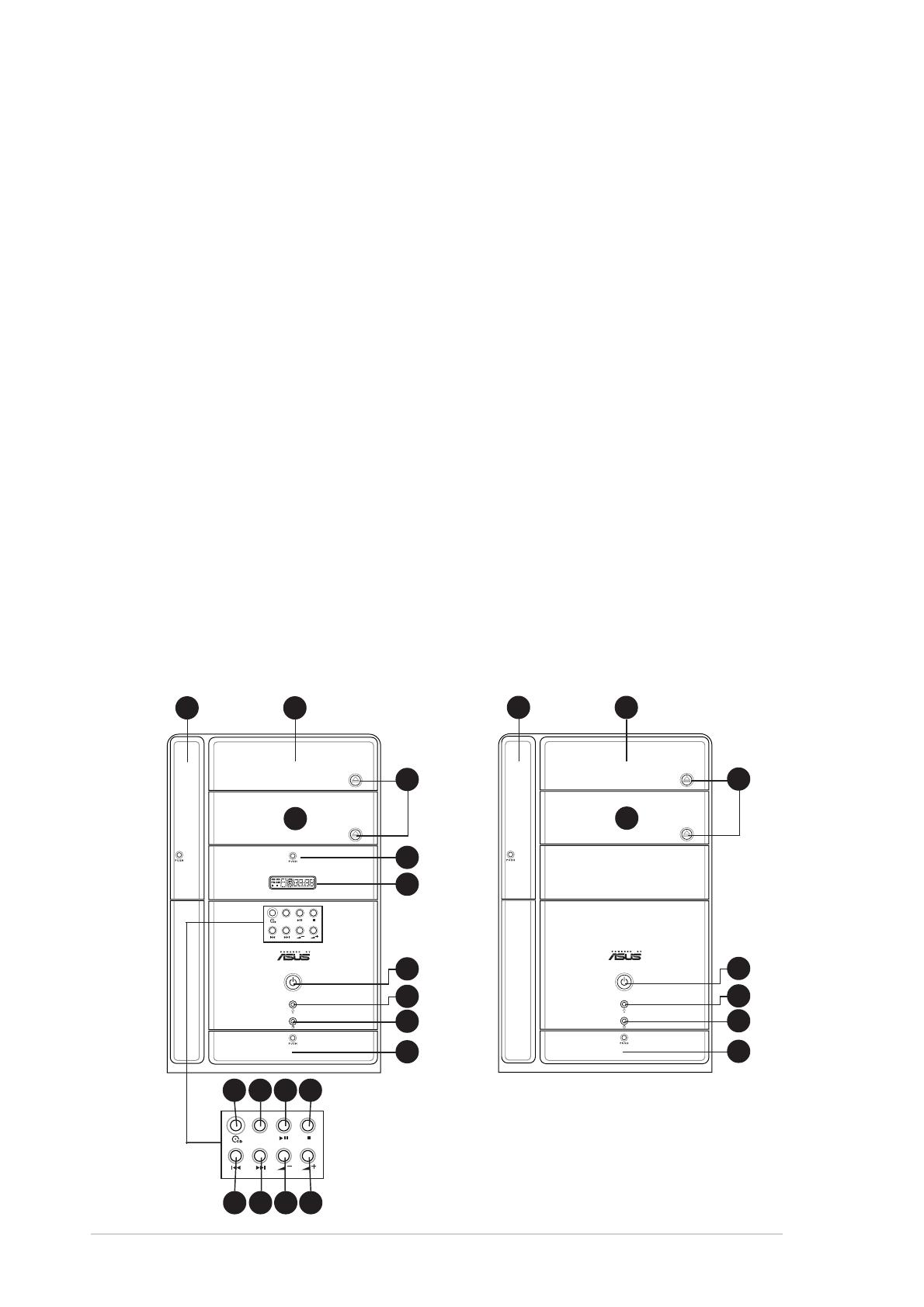
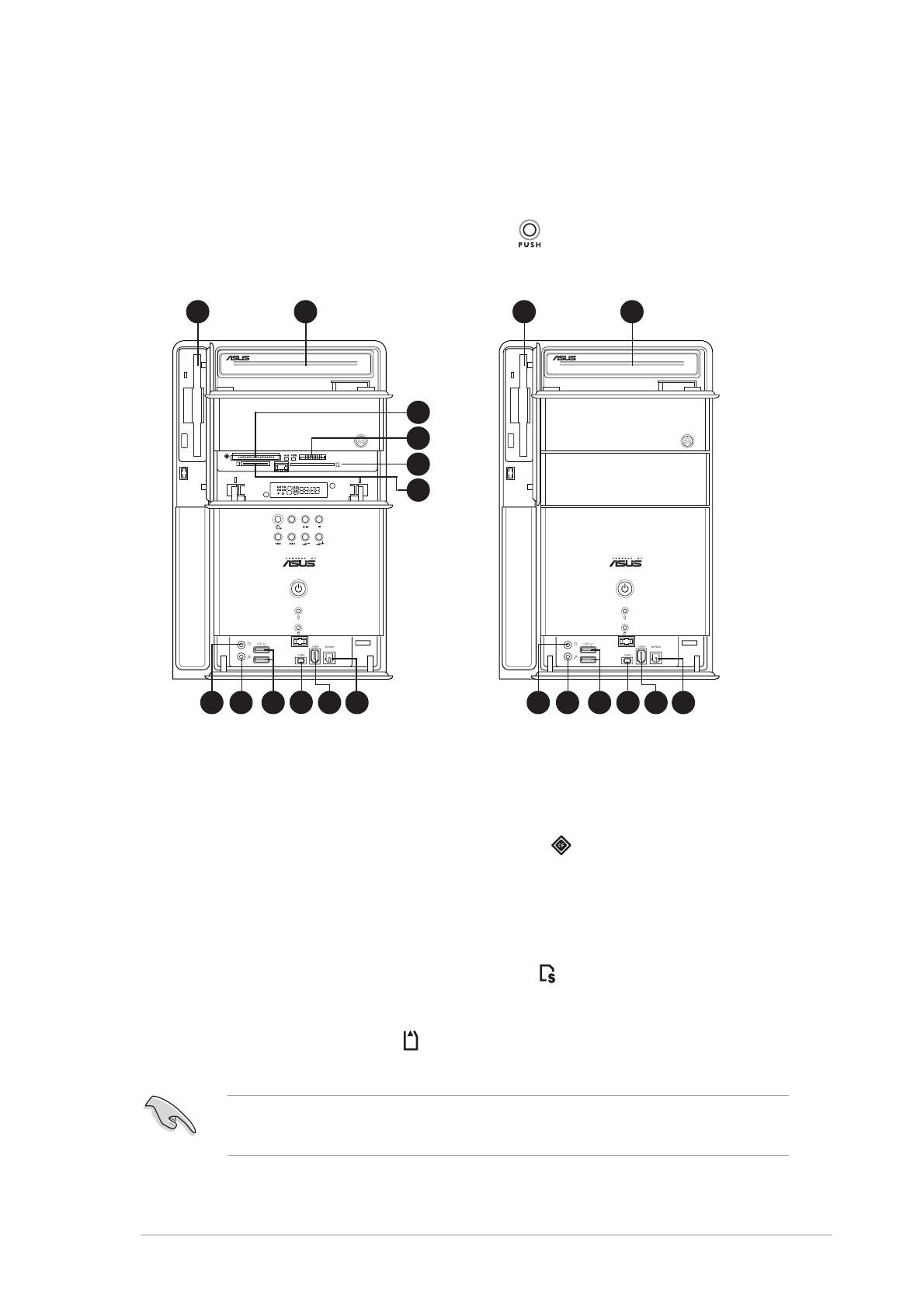
1.2 Front panel (external)
The front panel includes the system and audio control buttons, system
LEDs, and LED panel.
Deluxe model Basic model
MODE
21
3
4
10
9
5
8
6
7
21
3
4
5
8
6
7
MODE
11 12 13 14
15 16 17 18
15
ASUS Terminator 2 barebone system
1. Floppy drive door. Open this door to access the floppy disk drive.
2. Optical drive door. This door opens when you eject the loading tray.
3. Eject button. Press this button to eject the loading tray of the optical
drive.
4. Second optical drive door. This door covers a second optical drive
bay.
5. Power button. Press this button to turn the system on.
6. Power LED. When lit, this LED indicates that the system is ON.
7. HDD LED. This LED lights up when data is being read from or written
to the hard disk drive
8. Front panel I/O door. Open this door to show the front panel input/
output ports.
9. Storage card reader door (Deluxe models only). Open this door to
access the 6-in-1 storage card reader.
10. LED panel (Deluxe models only). The LED panel displays the audio
medium (CD/FM), radio frequency, player status (
/ ), real time clock,
track number, and time. See page 22 for details.
The following front panel buttons are activated only when the system is
in Audio DJ mode. The Audio DJ feature allows you to play CD audio
tracks, or tune into an FM radio station without entering the operating
system. See page 46 for details. The audio control buttons are
available on Deluxe models only.
11. CD button ( ). Press this button to put the Audio DJ function to CD
mode.
12. Mode button. Press this button to switch from CD to FM radio mode
or vice versa.
In Windows
®
mode, pressing this button shuts down, restarts, or puts
the system in sleep mode (S3) depending on the OS setting.

16
Chapter 1: System introduction
13. PLAY/PAUSE button ( / ). Press this button to perform various
functions in different modes.
In CD mode, plays or pauses an audio CD track.
In Radio mode, scans the available FM stations when pressed for
less than 2 seconds or presets a station when pressed for more than
2 seconds. Refer to page 22 on how to preset a radio station.
14. STOP button ( ). Press this button to stop the audio track being
played.
15. PREVIOUS button (
). Press this button to perform various functions
in different modes.
In CD mode, selects the previous audio track.
In Radio mode, selects the previous preset station.
16. NEXT button (
). Press this button to perform various functions in
different modes.
In CD mode, selects the next audio track.
In Radio mode, selects the next preset station.
17. Volume down button (
–
). Press this button to decrease the
system volume.
18. Volume up button (
+
). Press this button to increase the system
volume.
17
ASUS Terminator 2 barebone system
1.2 Front panel (internal)
The optical drive(s), storage card reader slots, and several I/O ports are
located inside the front panel doors.
Open the front panel doors by pressing the
mark.
MODE
2019
21
22
23
24
25 26 27 28 29 30
2019
25 26 27 28 29 30
19. Floppy disk drive. This drive is for 1.44MB, 3.5-inch floppy disk.
20. Optical drive. This is an IDE optical drive.
21. CompactFlash
®
/Microdrive™ card slot ( ). This slot is for a
CompactFlash
®
/Microdrive™ storage card.
22. Memory Stick
®
/Memory Stick Pro™ card slot. This slot is for a
Memory Stick
®
/Memory Stick Pro™ storage card.
23. Secure Digital™/MultimediaCard slot (
). This slot is for a Secure
Digital™/MultimediaCard storage card.
24. SmartMedia
®
card slot ( ). This slot is for a SmartMedia
®
storage
card.
You can not close the storage card reader door if a storage card is
inserted into any of the card slots.
Deluxe model
Basic model
28

18
Chapter 1: System introduction
25. Headphone port. This port connects a headphone with a stereo
mini-plug.
26. Microphone port. This Mic (pink) port connects a microphone.
Audio ports function variation
Port Headphone/2-Channel 4-Channel 6-Channel
Light Blue Line In No function LFE Output*/Center
Lime Line Out Front Speaker Out Front Speaker Out
Pink Mic In Surround Surround
* Low Frequency Enhanced Output
27. USB 2.0 ports. These Universal Serial Bus 2.0 (USB 2.0) ports are
available for connecting USB 2.0 devices such as a mouse, printer,
scanner, camera, PDA, and others.
28. 4-pin IEEE 1394 port. This port provides high-speed connectivity for
IEEE 1394-compliant audio/video devices, storage peripherals, and
other PC devices.
29. 6-pin IEEE 1394 port. This port provides high-speed connectivity for
IEEE 1394-compliant audio/video devices, storage peripherals, and
other PC devices.
30. Optical S/PDIF port. This port connects your audio system for
5.1-channel surround sound and enhanced 3D audio.

19
ASUS Terminator 2 barebone system
1.4 Rear panel
The system rear panel includes the power socket and several I/O ports
that allow convenient connection of devices.
1. GAME/MIDI port. This port connects a joystick, or game pad for
playing games, and MIDI devices for audio editing.
2. Telephone port (optional). This port connects an RJ-11 cable jack.
Connect one end of an RJ-11 cable to this port and the other end to
the RJ-11 port of the telephone unit.
3. RJ-11 port (optional). This port connects an RJ-11 cable jack.
Connect one end of an RJ-11 cable to this port and the other end to
the RJ-11 wall socket.
4. Serial port. This port connects a mouse, modem, or other devices
that conforms with serial specification.
5. PS/2 mouse port. This green 6-pin connector is for a PS/2 mouse.
6. PS/2 keyboard port. This purple 6-pin connector is for a PS/2 keyboard.
7. VGA port. This port connects a VGA monitor.
1
4
15
2
3
5
6
7
8
9
10
11
12
13
14
16
17
18
20
19
26
21 22
Deluxe model
(Consumer edition)
Deluxe model
(Commercial edition)
252423
252423

20
Chapter 1: System introduction
8. Parallel port. This 25-pin port connects a printer, scanner, or other
devices.
9. Line Out port. This Line Out (lime) port connects a headphone or a
speaker. In 4/6-channel mode, the function of this port becomes Front
Speaker Out.
10. Line In port. This Line In (light blue) port connects a tape player or
other audio sources. In 6-channel mode, the function of this port
becomes Low Frequency Enhanced Output/Center.
11. Microphone port. This Microphone (pink) port connects a
microphone. In 4/6-channel mode, the function of this port becomes
Surround Speaker.
12. USB 2.0 ports. These Universal Serial Bus 2.0 (USB 2.0) ports are
available for connecting USB 2.0 devices such as a mouse, printer,
scanner, camera, PDA, and others.
13. Ethernet LAN port. This port allows connection to a Local Area
Network (LAN) through a network hub.
14. AGP slot cover. Remove this cover when installing an AGP card.
15. Chassis fan. This fan provides ventilation inside the system chassis.
16. Radio antenna port. This port connects an optional radio antenna.
17. Power supply unit fan. This fan provides ventilation inside the
power supply unit.
18. Power socket. This socket connects the power cable and plug.
19. Voltage selector. This switch allows you to select the appropriate
voltage supply in your area. See the “Voltage selector” section on
page 40 before adjusting this switch.
20. Expansion card lock. This metal lock secures installed expansion
cards. See page 33 for details.
21. Video In port. (Deluxe models-Consumer edition only.) This port
connects a video casette recorder.
22. Cable TV connector. (Deluxe models-Consumer edition only.) This
connects a cable TV twist-on connector.
23. Wireless LAN adapter antenna connector. This connects the
dipolar antenna of the wireless LAN adapter.
24. Link LED. This yellow LED lights up when the wireless LAN adapter
radfio is on but has no activity.
/