Page is loading ...

www.johnsonandstarley.co.uk
sustainable solutions under one roof
HEATING HOT WATER VENTILATION
QUANTEC SYSTEM
ErP
High Efficiency Boiler
Quantec 24S ErP - G.C. No. 41-416-16
These instructions are to be left with the User
Publication No. ZZ 1434-8
Feb 2017
INSTALLATION, COMMISSIONING
& SERVICING INSTRUCTIONS

www.johnsonandstarley.co.uk
2
In the interest of continuous development Johnson and Starley reserve the right to change specication without prior notice.
Johnson and Starley prides itself on it’s ability to supply spare parts quickly and efciently.
PLEASE READ THESE INSTRUCTIONS CAREFULLY BEFORE STARTING INSTALLATION.
LEAVE THESE INSTRUCTION WITH THE USER OR AT THE GAS METER AFTER INSTALLATION
The Benchmark Scheme
Benchmark places responsibilities on both manufacturers and installers. The purpose is to ensure that
customers are provided with the correct equipment for their needs, that it is installed, commissioned and
serviced in accordance with the manufacturer’s instructions by competent persons and that it meets the
requirements of the appropriate Building Regulations. The Benchmark Checklist can be used to demonstrate
compliance with Building Regulations and should be provided to the customer for future reference.
Visit www.centralheating.co.uk for more information.
Installers are required to carry out installation, commissioning and servicing work in accordance with the Benchmark Code of Practice which is available
from the Heating and Hot water Industry Council who manage and promote the Scheme.
CONTENTS
The Benchmark Scheme 2
1 Features 3
2 General Description 3
3 Building Standards & Regulations 4
4 Safety, Electrical & Gas Information 4
General Safety Information
Handling the unit
Operating the Appliance
Electrical Supply
Gas Supply
5 Fiche ErP Technical Data 5
Technical Data
Performance Data
6 Preparation 8
Electrical Connections
Water Connections
Gas Connection
Condensate Drain
Boiler Control Interlock
Thermostatic Radiator Valves
Positioning
Timber Frame Buildings
Bathroom Installation
Compartment Installations
Room Ventilation
7 Dimension & Clearances 10
8 Heating System 11
Expansion Vessel
Pressure Gauge
Pressure Relief Valve
Filling Loop
Pipework Sizing
Domestic Hot Water Requirements
Water Flow Schematic
9 Installation Instructions 13
Carton Contents
Wall Mounting Template
Fixing the Appliance
10 Flue Instructions 14
Flue Configuration
Diagram of Terminal Positions
Types of Flue Systems
Flue Terminal Positions
Plume Outlets
Flue Requirements & General Information
Conventional 60/100mm Flue Accessories Part No.s
Optional Roof Outlets
The Standard Horizontal Flue System
Installation of the Standard Horizontal Flue System
11 Condensate Drain 20
Use of a Condensate Pump to External Termination
External Termination
Unheated Internal Area’s
12 Electrical 21
Drop Down Control Panel
Electrical Connections
Internal Wiring
To Add Thermostat/Programmer
Thermostats & Timer Kits
Operational System Control
Electrical Testing
13 Wiring Diagram 22
14 Connections & Filling 23
Water Connection for Central Heating
Condensate Drain
Pressure Relief Valve
Filling the Boiler
Gas Connection
15 Commissioning 23
Check Gas Installation
Air Purge Function
Initial Lighting
Central Heating
Domestic Hot Water
Check the Operational Gas inlet Pressure
General Checks DHW Mode
CH & DHW Mode
Flushing the System & Water Circulation
Balance the System
Water Temperatures
16 Handing Over 27
Instructing the User
Loss of Water Pressure
17 Servicing & Maintenance 27
Service Schedule
Initial Inspection
Servicing Sequence
Flue Inspection & Checks
Gaining Access to the Boiler
Control Panel & Front Door Removal
Fan Removal
Burner Assembly Removal
Heat Exchanger
Condensate Trap
18 Parts Replacements 30
Part Replacements without Draining the System
Draining the Appliance & System
19 Fault Finding Flowcharts & Blocking Codes 34
20 List of Spares 39
21 Benchmark Checklist and Service Record 41
Code of Practice
Commissioning Checklist
Service Record

3
Sales/Spares 01604 707012 Replacement Help Line 01604 707011
1. FEATURES
Appliance Classification:
The QuanTec System has been tested
and CE certified by B.S.I Ltd for use with
NATURAL Gas G20.
2. GENERAL DESCRIPTION
2.1 The QuanTec System appliance is a high efficiency boiler, designed to provide central heating. It’s design is room
sealed, taking combustion air from outside and expelling the products of combustion back to the outside.
Standard features include full sequence automatic spark ignition, low water content stainless steel heat exchanger,
automatic bypass and boiler frost protection, a daily pump and divert valve exercise.
Variable CH fitted on the user control.
• Central heating (CH) output is fully modulating with a range of: 4.8 to 24.2kW.
The boiler features a comprehensive diagnostic system which gives detailed information on the boiler status when
operating, and performance of key components to aid commissioning and fault finding.
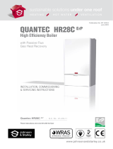
FEATURES
1
Rain Trap
2
Flue Sensor
3
View Port
4
Heat Exchanger
5
Ignition/Detection Electrode
6
Flow Thermistor Sensor
7
Condensate Trap
8
Condensate Pipe
9
Control Panel
10
Gas Valve
11
Pump
12
CH Water Pressure Sensor
13
Automatic Air Vent
14
Pressure Relief Valve
15
Fan
16
Burner Injector
17
Venturi
18
Expansion Vessel
19
Central offset flue adapter
FIGURE 1. QUANTEC SYSTEM FEATURES
3
5
1
4
6
9
8
19
18
16
17
15
14
13
12
11
7
10
2

www.johnsonandstarley.co.uk
4
3. BUILDING STANDARDS & REGULATIONS
STATUTE LAW DEFINES THAT ALL GAS APPLIANCES MUST BE INSTALLED BY
COMPETENT PERSONS, i.e. GAS SAFE REGISTERED INSTALLERS.
GAS SAFE MEMBERSHIP ENQUIRIES TEL: 0800 408 5500 IN ACCORDANCE WITH
THE GAS SAFETY (INSTALLATION AND USE) REGULATIONS (CURRENT EDITION).
FAILURE TO COMPLY WITH THESE REGULATIONS MAY LEAD TO PROSECUTION.
3.1 INSTALLATION REGULATIONS
• Building Standards (Scotland) (Consolidation) Regulations
• Building Regulation Part L
• Gas Safety (Installation and Use) Regulations (as amended)
• The Water Fittings Regulations or Water by-laws in Scotland
• Building Regulation (Northern Ireland)
• Model and Local Authority Byelaws
• Health & Safety Document No. 635.
• The Electricity at Work Regulations, 1989.
• Institute of Electrical Engineers (I.E.E) Wiring Regulations
• EU Regulation No 811/2013 and No. 812/2013 supplement Directive 2013/20/EU
This appliance has been Tested and Certified in order to meet the necessary European Directives and comply with the
latest Building Regulations, including the efficiency requirements of the SEDBUK scheme.
• Efciency of Hot Water Boilers Directive 92/42/EEC
• Gas Appliance Directive 2009/142/EC
• Low Voltage Directive 2006/95/EEC
• Electromagnetic Compatibility Directive 93/68/EEC
3.2 BUILDING STANDARDS AND REGULATIONS
Where no specific instructions are given, reference should be made to the relevant British Standard Code of Practice.
BS 5440:1 Flues (for gas appliances of rated input not exceeding 70 kW).
BS 5440:2 Ventilation (for gas appliances of rated input not exceeding 70 kW).
BS EN 12828 Heating Systems in buildings: Design for water based heating systems.
BS EN 12831 Heating Systems in buildings: Method for calculation of the design heat load.
BS EN 14336 Heating Systems in buildings: Installation and commissioning of water based heating systems.
BS 5546 Installation of gas hot water supplies for domestic purposes (2nd Family Gases)
BS 6798 Installation of gas fired hot water boilers of rated input not exceeding 70 kW.
BS 6891
Installation of Low Pressure Gas Pipework of up to 28 mm (R1) in domestic premises (2nd family gases).
IMPORTANT: This appliance is CE certificated for safety and performance. It is important that no modifications are made to
this appliance, unless fully approved in writing by Johnson & Starley Ltd. If in doubt please ring Johnson & Starley Ltd on
Telephone 01604 762881.
4. SAFETY, ELECTRICAL & GAS INFORMATION
PLEASE READ THESE INSTRUCTIONS CAREFULLY BEFORE COMMENCING WITH THE INSTALLATION
4.1 GENERAL SAFETY INFORMATION
4.1.1 An LPG unit should not be installed in a room or internal space below ground level unless one side of the sides
of the building is open to the ground.
4.1.2 Only use QuanTec original spare parts on this appliance. Failure to do so will invalidate the guarantee.
4.1.3 No artificially softened water must not be used to fill the central heating system.
4.1.4 The system can be damaged by debris entering the heat exchanger and reduce efficiency. It is recommended
that the boiler is flushed, follow these guidelines as this will protect the boiler and prolong its life.
4.1.5 It is important that the system is flushed thoroughly before the appliance is left to operate (as recommended in BS
7593)
in order to maintain an efficiently operating heating system. For replacement installations, the system MUST
be flushed with the old boiler in situ, in order to prevent the QuanTec becoming a trap for system debris. Once the
system has been flushed, an inhibitor (suitable for stainless steel heat exchangers) should be added. Appropriate
inhibitors are available, for example Sentinel, Fernox and Salamander. We also recommend a Magnetic & Non
Magnetic Filtration system is fitted between the last radiator and the boiler.
4.1.6 Failure to carry out the above procedure will invalidate the guarantee!

5
Sales/Spares 01604 707012 Replacement Help Line 01604 707011
GAS LEAKS
DO NOT OPERATE ANY ELECTRICAL SWITCHES, OR USE A NAKED FLAME
TURN OFF THE GAS SUPPLY. VENTILATE THE AREA BY OPENING DOORS AND
WINDOWS. CALL THE NATIONAL GAS EMERGENCY SERVICE ON
0800 111999
4.2 HANDLING THE UNIT
4.2.1 The weight of this appliance exceeds that recommended for a one-man lift. It will therefore be necessary to gain
assistance at times during the removal from its packaging and during installation procedure. Manoeuvring the
boiler may include the use of a sack truck and involve lifting, pushing and pulling.
4.2.2 It should be noted that this appliance may contain sharp edges. Care MUST be taken when handling the appliance
to prevent injury. We advise the engineer to wear suitable P.P.E.
4.2.3 Once the appliance has been fired beware that certain parts will be hot to the touch.
4.2.4 Do not install flues during rain, high winds or in severe weather conditions.
4.2.5 The manufacturers instructions supplied must not be taken as overriding any statutory requirements.
4.3 OPERATING THE APPLIANCE
4.3.1 This appliance is not intended for use by persons (including children) with reduced physical, sensory or mental
capabilities, or lack of experience and knowledge, unless they have supervision or been given instruction
concerning use of the appliance by a person responsible for their safety.
4.3.2 Children should be supervised to ensure they do not play with the appliance.
4.4 ELECTRICAL SUPPLY
4.4.1 Ensure the mains supply voltage, frequency, number of phases and power rating comply with details on
the rating label.
4.4.2 All wiring must be in accordance with the appropriate standards. The equipment must be supplied with a double
pole isolator switch and for new heating systems, and where practical replacement installations, the isolator shall
be situated adjacent to the appliance.
4.4.3 Ensure safety regulations and practices are adhered to when installing and using this appliance.
4.5 GAS SUPPLY
4.3.1 It is the responsibility of the Gas Installer to size the gas installation pipework in accordance with BS 6891. Whilst
the principle of the 1:1 gas valve ensures the QuanTec range is able to deliver it’s full output at inlet pressures as
low as 14mb, other gas appliances in the property may not be as tolerant. When operating pressures are found to
be below the minimum meter outlet of 19mb these should be checked to ensure this is adequate for correct and
safe operation.
4.3.2 Allowing for the acceptable pressure loss of 1mb across the installation pipework, it can be assumed that a mini-
mum permitted operating pressure of 18mb will be delivered to the inlet of the appliance. (Reference BS 6400-1
Clause 6.2 Pressure Absorption).
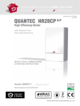
4.3.3 The external gas cock could further reduce the operating pressure when measured at its test point. The pressure
drop is relative to the heat input to the boiler (kW), see Figure 2.
IMPORTANT: Installation pipes must be fitted in accordance with BS 6891. In IE refer to IS.813.
FIGURE 2. GAS COCK PRESSURE DROP
3
2.5
2
1.5
1
0.5
0
PRESSURE DROP (mbar)
0.0 0.5 10.0 15.0 20.0 25.0 30.0 35.0 40.0 45.0
HEAT INPUT TO BOILER (kW)

www.johnsonandstarley.co.uk
6
5. TECHNICAL DATA
EU Regulations No. 811/2013 and No. 812/2013 supplementing Directive 2010/30/EU.
TABLE 1. ErP TECHNICAL DATA 24S
PRODUCT DATA SYMBOL
VALUE UNIT
Condensing boiler - Yes -
Low temperature boiler - No -
B11 Boiler - No -
Cogeneration space heater - No -
Combination Heater - No -
Rated heat output Prated 23 kW
Seasonal space heating energy efficiency ŊS94 %
Energy efficiency class - A -
USEFUL HEAT OUTPUT
At rated heat output and high temperature regime P423.4 kW
At 30% of rated heat output and low temperature regime P17.8 kW
USEFUL EFFICIENCY
At rated heat output and high temperature regime Ŋ487.9 %
At 30% of rated heat output and low temperature regime Ŋ199.1 %
AUXILIARY ELECTRICITY CONSUMPTION
At full load elmax 0.025 kW
At part load elmin 0.013 kW
In standby mode PSB 0.007 kW
OTHER ITEMS
Standby heat loss
PSB 0.099 kW
Ignition burner power consumption
Pign 0 kW
Sound power level indoors L
WA
45 dB
1. High temperature regime means 60°C return temperature at heater inlet and 80°C feed temperature at
heater output.
2. Low temperature means for condensing boiler 30°C, for low temperature boilers 37°C and for other
heaters 50°C return temperature (at heater).

7
Sales/Spares 01604 707012 Replacement Help Line 01604 707011
* The value is used in the UK Government’s Standard Assessment Procedure (SAP) for energy rating of dwellings.
The test data from which it has been calculated have been certified by a notified body.
NOTE: Gas consumption is calculated using a calorific value of 38.7 MJ/m³ gross or 34.9 MJ/m³ nett. To obtain the
gas consumption at a different calorific value:
a. For l/s - divide the gross heat input (kW) by the gross C.V. of the gas (MJ/m³)
b. For ft³/h - divide the gross heat input (Btu/h) by the gross C.V. of the gas (Btu/ft³)
c. For m³/h - multiply l/s by 3.6
TABLE 2. TECHNICAL DATA
24S
Maximum weight lift
48kg
Gas supply
2H - G20 - 20mbar
Gas connection
15mm copper
Injector size
4.75mm
Domestic hot water flow and return
15mm copper
Heating flow and return
22mm copper
Safety valve discharge
15mm copper
Flue terminal diameter
100mm (4”)
Condense drain
21.5mm plastic overflow pipe
Maximum heating system water content using fitted expansion vessel
73lts
Electrical supply
230V ~ 50Hz
Electrical rating
100W
External fuse rating
3A
Expansion vessel capacity
8 litres
Expansion vessel initial charge pressure
1.0 bar
Heating system minimum pressure
0.7 bar
Ball valves are fitted in water and gas connections
For larger systems use an additional expansion vessel
TABLE 3. PERFORMANCE DATA 24S
PERFORMANCE DATA
MAXIMUM MINIMUM
Burner CO² (%)
case off
9.4 8.6
case on
9.7 8.9
± 0.5
PERFORMANCE DATA FOR CENTRAL HEATING
CH input Q Net
kW 24 4.7
Gross
kW 26.6 5.2
Gas Consumption
m³/h 2.47 0.48
CH Output
Non condensing kW 23.4 4.58
Condensing
kW 25.6 5.17
Seasonal Efciency
SEDBUK 2005
A
SEDBUK 2009
89.5
NoX Classication
CLASS 5 34mg/kWh
Central Heating set point temperature range
20 - 82°C

www.johnsonandstarley.co.uk
8
6. PREPARATION & POSITIONING
6.1 PREPARATION
6.1.1 ELECTIRCAL CONNECTIONS: Make sure all the electrical cables are in place.
6.1.2 WATER CONNECTIONS: Important. A minimum length of 1 metre of copper pipe MUST be fitted to both
flow and return connections from the boiler before connection to any plastic piping.
6.1.3 The central heating system should be in accordance with BS 6798 and for smallbore and microbore
systems, BS 5449.
6.1.4 Water treatment - see paragraph 8.3.
6.1.5 GAS CONNECTIONS: Make sure the gas connections are in place.
6.1.6 Give consideration to the flue position. Pluming will occur at the terminal so terminal positions where this
could cause a nuisance should be avoided. See section 10.
6.1.7 Give consideration to the overall height.
6.1.8 CONDENSE DRAIN: This drain must be connected to a drainage point on site. All pipework and fittings in
the condensate drainage system MUST be made of plastic - no other materials may be used.
IMPORTANT: Any external runs must be in accordance with BS 6798. The drain outlet on the boiler is
sized for standard 21.5mm (¾”) overflow pipe.
6.1.9 BOILER CONTROL INTERLOCK: Central heating systems controls should be installed to ensure the
boiler is switched off when there is no demand for heating, in compliance with Building Regulations.
6.1.10 THERMOSTATIC RADIATOR VALVES: Heating systems utilising full thermostatic radiator valve control of
temperature in individual rooms should also be fitted with a room thermostat controlling the temperature
in a space served by radiators not fitted with such a valve. The space heating temperature control over
a living/dining area or hallway having a heating requirement of at least 10% of the minimum boiler heat
output should be achieved using a room thermostat, whilst other rooms are individually controlled by
thermostatic radiator valves. However, if the system employs thermostatic radiator valves on all radiators,
or two port valves, then a bypass circuit must be fitted with an automatic bypass valve to ensure minimum
flow is maintained.
6.2 POSITIONING
6.2.1 The boiler must be installed on a flat and vertical internal wall, capable of adequately supporting the
weight of the boiler and any ancillary equipment.
6.2.2 The appliance is not suitable for external installation unless it is protected from the elements by a suitable
enclosure. The enclosure must provide the required clearances for installation, servicing and maintenance
as well as the correct level of ventilation. The selected position should allow for a suitable flue system to
be installed.
6.2.3 The boiler may be installed in any room or internal space, although particular attention is drawn to the
requirements of the current IEE (BS 7671) Wiring Regulations and the electrical provisions of the building
regulations applicable in Scotland, with respect to the installation of the boiler in a room or internal space
containing a bath or shower. For IE reference should be made to the current ETCI rules for electrical
installations and I.S. 813.
6.2.4 TIMBER FRAME BUILDINGS: When installed in a timber frame building guidance should be taken from
the gas industry publication IGE/UP-7 (Guide for Gas Installations in Timber Frame Housing). BS 6798
gives details of the essential features for a compartment or cupboard where a gas appliance is to be
installed. An existing cupboard may require modification.
ZONE 0
6.2.5 BATHROOM INSTALLATIONS
If the appliance is installed in a room
containing a bath or shower it is
important to locate the electrical switch
in a position where it cannot be touched
by anyone using the bath or shower.
The current IEE Wiring Regulations (BS
7671) for England and the electrical
provision of the Building Regulations for
Scotland gives details. The appliance
must be installed beyond Zone 2, as
detailed in BS 7671. A compartment
used to enclose the boiler should be
designed and constructed specially for
this purpose.
FIGURE 3. BATHROOM ZONES

9
Sales/Spares 01604 707012 Replacement Help Line 01604 707011
6.2.6 COMPARTMENT INSTALLATIONS: An existing cupboard or compartment may be used, provided that
it is modified for the purpose. In both cases, details of essential features of cupboard / compartment
design, including airing cupboard installation, are to conform to the following:
• BS 6798 (No cupboard ventilation is required - see ‘Air Supply’ for details).
• The position selected for installation MUST allow adequate space for servicing in front of the boiler.
• For the minimum clearances required for safety and subsequent service, see the wall mounting template
and section 7. In addition, sufficient space may be required to allow lifting access to the wall mounting
bracket.
6.3 ROOM VENTILATION: It is not necessary as the appliance draws it’s combustion air from outside of the building
and cupboard or compartment ventilation is not necessary providing that the minimum clearances are maintained.
However, reference should be made to BS 5440 Pt. 2
7. DIMENSIONS & CLEARANCES
7.1 DIMENSIONS
7.1.1
It is recommended that where the appliance is located in a kitchen, or next to other combustible materials,
a gap of 5mm be left on either side and where the flue run is through a void in kitchen units, again
a minimum gap of 5mm should be left. For the purpose of servicing, it is also recommended that the
appliance be located with a minimum gap of 200mm above any surface.
*Note: A minimum 450mm dimension is a desired workable clearance for servicing.
7.1.2 The boiler connections are made on the boiler connection tails.
7.1.3 The minimum clearances must be maintained for operation and servicing.
7.1.4 Additional space will be required for installation, depending upon site conditions.
7.2 CLEARANCES
7.2.1 Bottom clearance after installation can be reduced to 5mm. This must be obtained with an easily removable
panel, to enable the consumer to view the system pressure gauge, and to provide the 200mm clearance
required for servicing.
7.2.2 The minimum front clearance when built in to a cupboard is 5mm from the cupboard door but 450mm
overall clearance is still required, with the cupboard door open, to allow for servicing.
423 321
123
212
183
780
FIGURE 4. QUANTEC REGULAR KOMPACT DIMENSIONS
FIGURE 5.
FLUE CLEARANCES KITCHEN LAYOUT - TOP VIEW
450mm

www.johnsonandstarley.co.uk
10
8. HEATING SYSTEM
8.1 The installation must comply with all relevant national and local regulations.
All components of the system must be suitable for a working pressure of 3 bar and temperature of 110°C. Extra
care should be taken in making all connections so that the risk of leakage is minimised.
NOTE: a. The method of filling, refilling, topping up or flushing sealed primary hot water circuits from the
mains via a temporary hose connection is only allowed if acceptable to the local water authority.
b. Antifreeze fluid, corrosion and scale inhibitor fluids suitable for use with boilers having stainless
steelheat exchangers may be used in the central heating system.
8.2 EXPANSION VESSEL: The integral expansion vessel is pre-charged to a pressure of between 0.5 and 1.0 bar.
This should be checked before the water system is filled. Details below show the water system volume that is
acceptable for this vessel. If the system water volume is larger then an additional vessel must be fitted to the
system. BS 5449 and BS 6798 gives further details regarding expansion vessel sizing and sealed systems. See
Table 3.
8.3 PRESSURE GAUGE: The appliance has two components that monitor pressure. Firstly there is a mechanical
pressure gauge on the CH flow outlet, this allows the heating system to be pre-plumbed and filled with a visual
check on the pressure. The second is an electronic device used by the microprocessor control to monitor the
system pressure and block the heat input, should there be a lack of pressure.
8.4 PRESSURE RELIEF VALVE: The pressure relief valve protects the system from over pressurisation. It is set to be
fully open at 3 bar, however it will start to open at approximately 2.7 bar. It should not be used to flush the system.
Using no less than 15 mm diameter copper pipe, the discharge pipe must be extended to a safe place outside the
building. The discharge position must be visible, not onto a public access area or above any window or entrance.
The pipe must have a continuous fall and discharge to a safe place. It is possible that boiling water and/or steam
could be discharged if the safety valve operates.
8.5 FILLING LOOP:
A filling loop connection on the central heating return pipework must be provided to facilitate
initial filling and pressurising of the system plus any subsequent water loss replacement or refilling.
The filling method adopted must be in accordance with all the relevant water supply regulations and use approved
equipment
.
The sealed primary circuits may be filled or replenished by means of a temporary connection between the circuit
and a supply pipe, provided a ‘listed’ double check valve or some other no less effective backflow prevention
device is permanently connected at the inlet to the circuit and the temporary connection is removed after use.
8.6 PIPEWORK SIZING
: In order to keep the noise of the system to a minimum, the velocity of water should be kept
below 1.5 m/s and it should be noted that the appliance is designed to operate with a temperature differential of
20˚C between flow and return. The maximum flow rates are 0.3 kg/s which, through a 22mm pipe, gives velocities
of 1.00 m/s. Therefore, the recommended minimum pipe size for the main carcass is 22mm.
TABLE 4. EXPANSION VESSEL REQUIREMENTS
Vessel charge and initial system pressure bar
bar 0.5 0.75
1.0 1.5
Total water content of system using 8 litres
(1.45 gals) capacity expansion vessel supplied with appliance
L 95 84
73 50
For system having a larger capacity multiply the total system
capacity in litres by the factor to obtain the total minimum expansion
vessel capacity required litres
0.0833
0.09 0.109 0.156

11
Sales/Spares 01604 707012 Replacement Help Line 01604 707011
FIGURE 6. QUANTEC SYSTEM WATER FLOW SCHEMATIC
CH FLOW CH RETURN
GAS INLET
FLOW
THERMISTOR
RETURN
THERMISTOR
PUMP
LOW
PRESSURE
SWITCH
PRESSURE
RELIEF
VALV E

www.johnsonandstarley.co.uk
12
FIGURE 7. CARTON CONTENTS
9. INSTALLATION INSTRUCTIONS
9.1 WALL MOUNTING TEMPLATE
Use a plumb line to make sure the unit is square. Fix the template to the wall. Mark the positions of the flue
and 4 fixing points.
9.1.1 Using a 105 mm core drill make the hole through the wall. Installations that are made from within the
building only will require a 125 mm diameter hole in order to fit the flue system.
9.1.2 Using a 7mm bit, drill a minimum of 4
fixing holes for the wall plate. Insert the
Rawlplugs. Remove the template.
9.2 FIXING THE APPLIANCE
Caution: This appliance exceeds the
recommended weight for a one-man lift as
detailed in the Manual Handling Operations,1992
Regulations.
9.2.1
It should be noted this appliance could
contain sharp edges and care MUST be
taken when handling.
9.2.2 Screw the wall bracket to the wall using
the 4 screws provided.
9.2.3 Lift the appliance onto the fixing bracket
and lower into position.
FIGURE 8. FIXING BRACKET
GAS VALVE PACK
COPPER CONNECTIONS PACK
RETURN VALVE PACK
FLOW VALVE PACK
ACCESSORIES PACK
WALL
BRACKET
CARTON CONTENT
1
Quantec System Appliance 1
2
Group Set Components Pack 1
Gas Valve Pack
1
Return Valve Pack
1
Flow Valve Pack
1
Accessory Pack
1
Copper connection pack
1
3
Wall Mounting Plate 1
4
Wall Mounting Template 1
5
Installation & Users Instructions 1
INSTRUCTIONS
www.johnsonandstarley.co.uk
sustainable solutions under one roof
HEATING HOT WATER VENTILATION
INSTALLATION, COMMISSIONING
& SERVICING INSTRUCTIONS
QUANTEC HR28C
High Efficiency Boiler
with Passive Flue
Gas Heat Recovery
Quantec HR28C
- G.C. No. 47-416-11
These instructions are to be left with the User
Publication No. ZZ 1430-5
January 2015
WALL
TEMPLATE
FOR
QUANTEC
COMBI & SYSTEM
BOILERS
www.johnsonandstarley.co.uk
sustainable solutions under one roof
HEATING HOT WATER VENTILATION
USER’S INSTRUCTIONS
QUANTEC HR & COMBI
High Efficiency
Combination
Boilers
These instructions are to be left with the User
Publication No. ZZ 1431-2
January 2015
Quantec HR28C - G.C. No. 47-416-11
Quantec 30C - G.C. No. 47-416-12
Quantec 24C - G.C. No. 47-416-13

13
Sales/Spares 01604 707012 Replacement Help Line 01604 707011
FIGURE 9. FLUE CONFIGURATIONS
STANDARD HORIZONTAL FLUE
KIT OFFSET HORIZONTAL REAR FLUE EXTENDED
HORIZONTAL REAR FLUE
Standard flue
kit
comprising of:
Turret
Horizontal Terminal
Can be fitted to the left or the right.
Standard flue kit +
90˚ Elbow
Required Extension
Length
Can be fitted to the left
or the right.
Vertical Appliance
Adaptor
Horizontal Terminal
90˚ Elbow
Required Extension
Length
HORIZONTAL SIDE FLUE VERTICAL FLUE OFFSET VERTICAL FLUE
Can be fitted to the left or the right.
S
tandard Flue Kit comprising of
Turret
Horizontal Terminal
Vertical Appliance Adaptor
Required Extension Lengths
Vertical Terminal
Can be fitted to the left or the right.
Turret
Vertical Terminal
90˚ Elbow
Required Extension Lengths
FRONT SIDE FLUE
Can be fitted to the left or the right.
Standard Flue Kit +
90˚ Elbow
Required Extension
Length
10. FLUE INSTRUCTIONS
10.1 The QuanTec System Boiler is certified as a heating boiler with corresponding flue systems according to EU
Directive 90/396/EEC on gas-fired devices. These installation instructions are covered by this certification and are
referred to in the design approval test certificate.
10.2 The installation of the boiler and flue system must be in accordance with the Gas Safety (Installation and Use)
Regulations 1998 and the Building Regulations. If no specific instructions are given, reference should be made to
the relevant codes of practice.
THESE RELEVANT STANDARDS SHOULD BE FOLLOWED
BS 5440:1 Flues and ventilation for gas appliances of rated heating input not exceeding 70kW (net): Flues
BS 5440:2 Flues and ventilation for gas appliances of rated heating input not exceeding 70kW (net): Air Supply
Ensure all legislation, regulations and directives mentioned are observed.
10.3 The air/flue duct operates at very low temperatures therefore no clearance
is necessary between the air duct and the adjacent services.
10.4 Ensure while installation work is being carried out that no debris such as
swarf, filings or fragments of mortar remains in the air/flue duct.
10.5 FLUE CONFIGURATIONS

www.johnsonandstarley.co.uk
14
TABLE 4 TERMINAL POSITION MIN DISTANCE
A
Directly below an opening, air brick, opening window etc
300mm
B
Above an opening, air brick, opening window, etc.
300mm
C
Horizontally to an opening, air brick, opening window etc.
300mm
D
Below gutters, soil pipes or drain pipes.
75mm
E
Below eaves.
200mm
F
Below balconies.
200mm
G
From a vertical drain pipe or soil pipe.
150mm
H
From an internal or external corner. Greater than 450mm protrusion.
300mm
H
From an internal or external corner. Greater than 450mm protrusion.
300mm
I
Above ground, roof or balcony level.
300mm
J
From a surface facing the terminal.
600mm
K
From a terminal facing the terminal.
1,200mm
M
Vertically from a terminal on the same wall.
1,200mm
N
Horizontally from a terminal on the same wall.
300mm
Q
Above intersection with roof.
530mm
P
From a vertical structure on the roof
300mm
R
From the terminal to the boundary
300mm
FIGURE 10. FLUE TERMINAL POSITIONS

15
Sales/Spares 01604 707012 Replacement Help Line 01604 707011
10.6 TYPE OF FLUE SYSTEMS
10.6.1 The standard concentric flue system 60/100mm (100mm diameter).
10.6.2 A Flexible flue kit (FFK-5) 60/100mm (100mm diameter).
For further information contact the sales office at Johnson & Starley Ltd. Telephone 01604 762881.
10.6.3 The air/flue duct operates at very low temperatures therefore no clearance is necessary between the air
duct and the adjacent services.
10.7 FLUE TERMINAL POSITIONS
10.7.1 The following information provides the general requirements for siting flue terminals. As part of the
recommendation given in BS 1550 Part 1. For IE recommendations, see the current issue of I.S. 813
“Domestic Gas Installations.” Also publication a “Guide for Gas Installations in Timber Framed Housing
DM2” or consult your local gas region, MUST be consulted when installing the appliance into a timber-
framed building.
NOTE: Due to the nature of the boiler, water vapour will discharge from the flue. This should be taken into
account when siting the flue
10.7.2 Both the horizontal and vertical terminals must be positioned on the outside of the building and the free
passage of air must be available at all times. It is not recommended to position the terminal close to
projections especially under a balcony or near to a drainpipe.
10.7.3 Ensure that combustion products cannot enter the building where the heater is installed or near to any
other building where doors or windows may be open.
10.7.4 Recommended terminal positions for both horizontal and vertical flues are shown. See Table 4. For flue
components see Table 5.
10.7.5 Where the lowest part of the flue terminal is located less than 2 metres above the ground, a balcony or
above a flat roof across which there is access, the terminal MUST be fitted with a guard (Part No: 1000-
0019710) which is available from Johnson & Starley. The distance between the guard and the nearest
part of the terminal must not be less than 50 mm.
10.7.6 The flue MUST NOT be installed under a car port.
10.8 PLUME TERMINAL OUTLETS
10.8.1 A flue duct outlet of an appliance should be at least 600mm from the boundary line when facing it and at
least 300mm from the boundary line when running parallel to it. See Figure 11.
NOTE: When the flow of products is at an angle to the boundary, the 600mm dimension may be measured in the
direction of the flow, as long as the terminal is not less than 300mm from the boundary.
10.8.2 It is recommended the terminals are not sited within 2m of an opening in an adjacent building or within
2m of the boundary facing the terminal if the plume is likely to cause a nuisance to a neighbour, e.g
discharging over a walkway or patio.
10.9 FLUE REQUIREMENTS & GENERAL INFORMATION
10.9.1 Horizontal and vertical concentric flues (60/100mm diameter) with balanced terminals may be installed
on all the QuanTec appliances.
10.9.2 If an extended horizontal flue is being used it must have a continuous fall back towards the appliance of
3° (52mm) per meter. This ensures that condensate runs back into the appliance from the flue system for
safe discharge via the condensate waste pipe. Reference should be made to Table 5 for relevant part
numbers.
10.9.3 The maximum length of flue permissible is 12
meters including terminal
10.9.4 The minimum vertical flue length is 1.25m from
the top of the appliance case to the top of the
terminal.
10.9.5 Longer flues may be fitted, however the input
of the appliance will be reduced accordingly.
10.9.6 Elbows may be fitted within the flue system
with a corresponding reduction in overall flue.
10.9.7 Guidelines for the maximum flue length are as
follows.
HORIZONTAL FLUE VERTICAL FLUE
TURRET 90° ELBOW STRAIGHT
1m FLUE 90° ELBOW STRAIGHT
1m FLUE
1 - 10 - 10
1 1 8 1 8
1 2 6 2 6
1 3 4 3 4
When using 45° elbows: 2 x 45° elbow = 1 x 90° elbow
FIGURE 11. PLUME TERMINAL OUTLET DIMENSIONS

www.johnsonandstarley.co.uk
16
TABLE 5. DESCRIPTION COLOUR QTY APPLICATION PART No.
1
60/100 Standard Horizontal Flue Kit White 1 Horizontal 1000-0020070
2
Turret White 1 Horizontal 1000-0020020
3
800mm Horizontal Terminal White 1 Horizontal 1000-0019830
4
Vertical Appliance Adaptor White 1 Vertical 1000-0018990
5
45° Elbow White 1 Horizontal & Vertical 1000-0018970
6
90° Elbow White 1 Horizontal & Vertical 1000-0018980
7
250mm Straight Extension White 1 Horizontal & Vertical 1000-0018960
8
500mm Straight Extension White 1 Horizontal & Vertical 1000-0018950
9
1000mm Straight Extension White 1 Horizontal & Vertical 1000-0018940
10
2000mm Straight Extension White 1 Horizontal & Vertical 1000-0025570
11
Flat Roof Weather Collar 1 Vertical 1000-0020060
12
Pitched Roof Collar Black 1 Vertical 1000-0020030
13
Ridge Terminal Terracotta 1 Horizontal & Vertical 1000-0021030
14
Wall Fixing Bracket 100mm 1 Horizontal & Vertical 1000-0018930
15
1140mm Vertical Terminal
White/Black
1 Vertical 1000-0020740
16
Plume Management Kit Black 1 Horizontal & Vertical 1000-0020730
17
1000mm Extension Flue 60mm Black 1 Horizontal & Vertical 1000-0020740
18
90° Elbow 60mm Ø Black 1 Horizontal & Vertical 1000-0020680
19
45° Elbow 60mm Ø Black 2 Horizontal & Vertical 1000-0020670
20
Wall Fixing Bracket 60mm 1 Horizontal & Vertical 1000-0020770
21
Flexible Flue Kit 60/100mm Black 1 Flexible FFK5
22
Flexible Black Outer Pipe Black 1 Flexible 1000-0023410
23
Flexible Grey Inner Pipe Grey 1 Flexible 1000-0023420
24
Outer Rigid to Flex Adapter Grey 1 Flexible 1000-0023430
25
Inner Rigid to Flex Connector Grey 1 Flexible 1000-0023440
26
Outer Flex to Rigid Adapter Grey 1 Flexible 1000-0023450
27
Inner Flex to Rigid Connector Grey 1 Flexible 1000-0023460
28
Outer Seal Pipe Rings 2 Flexible 1000-0023470
29
Inner Seal Pipe Rings 2 Flexible 1000-0023480
30
Centalising Spacer Ring 1 Flexible 1000-0023490
31
Flue Support Kit 1 Flexible 1000-0023500
32
Draw Cone & Rope 1 Flexible 1000-0023510
33
Chimney Terminal Kit 60/100mm Black 1 Vertical CTK-60/100
34
Skyline Terminal & Outer Flue Cowl Black 1 Vertical 1000-0023990
35
Locking Ring Grey 1 Vertical 1000-0026610
36
Flashing Ring Grey 1 Vertical 1000-0026660
37
Chimney Cover Plate 1 Vertical 1000-0026600

17
Sales/Spares 01604 707012 Replacement Help Line 01604 707011
FIGURE 12. OPTIONAL ROOF OUTLETS
HORIZONTAL
TERMINAL
TURRET
CLAMP
FIGURE 13. STANDARD HORIZONTAL FLUE
10.12 THE STANDARD HORIZONTAL FLUE SYSTEMS
The standard horizontal flue kit comprises of:
The appliance comes with a wall template.
(Label Ref: 1000-2217950-3)
ITEM DESCRIPTION QTY
1 Turret 1
2 Appliance Seal 1
3 60/80 Adaptor 1
4 EPDM Outside Wall Cover Plate 1
5 Inside Wall Cover Plate 1
6 100mm Diameter Clamp 1
7 800mm Horizontal Terminal 1
10.11 OPTIONAL ROOF OUTLETS
FLAT ROOF PITCHED ROOF
PITCHED ROOF PITCHED ROOF SIDE VIEW
500mm
PITCHED ROOF
WEATHER
COLLAR
500mm
1140mm
FLAT ROOF
WEATHER
COLLAR
20˚ to 50˚
RIDGE
TERMINAL
CLAMPS
FLUE
EXTENSIONS
VERTICAL
APPLIANCE
ADAPTOR
ADJUSTABLE
LENGTH
RIDGE
TERMINAL

www.johnsonandstarley.co.uk
18
IMPORTANT NOTE: Before carrying out this procedure ensure seal
has not been dislodged from top of the boiler.
10.13.1 Using the template supplied with the boiler, determine the
position of the flue.
10.13.2 If access is available from outside drill a 105mm diameter
hole. If no access is available refer to section 2.
10.13.3 Mount the wall bracket and the boiler on the wall as detailed
in paragraph 9.1.
10.13.4 Fit the appliance seal to the underside of the turret and
fix the turret to the top of the boiler using the 4 screws
supplied, ensuring that the heat exchanger flue seal is in
place.
10.13.5 Take a measurement from the outside of the wall to the edge
of the turret dimension “X” Figure 14.
10.13.6 Mark this dimension onto the horizontal terminal as shown
in Figure 15.
10.13.7 Cut the flue to the desired length. Make sure the ends are
square and free from burrs and the inner plastic flue pipe is
chamfered.
NOTE: To ease the assembly of the flue components, apply suitable
silicone lubricant to the male plastic end. (Any other type of
lubricant may corrode the gasket.)
10.13.8 Place flue clamp over turret rim.
10.13.9 From the outside of the building, push the terminal through
the wall and locate the male plastic end of the terminal into
the female end of the turret.
10.13.10 Place clamp equally over the turret and terminal ends and
tighten the 2 screws.
10.13.11 Fit the rubber-finishing ring over the outside of the flue,
pushing it flush to the wall. The rib on the inside of the ring
will locate in-between the locating pips on the end of the
terminal.
10.14 NO OUTSIDE ACCESS
10.14.1 If no access is available from outside the building drill a
125mm diameter hole.
10.14.2 Mount the wall bracket and the boiler on the wall as detailed
para 9.1.
10.14.3. a. For a rear flue measure the wall thickness and add;
40mm for a standard rear flue 90mm for a rear flue if
the standoff bracket is used.
b. For a side flue measure the distance from the outside
wall to the side of the boiler and add; Length shown in
Figure 16. This dimension is known as dimension “X”.
10.14.4 Mark this dimension on to the turret as in Figure 14.
10.14.5 Cut the flue to the desired length. Make sure the ends are
square and free from burrs and the inner plastic flue pipe is
chamfered.
NOTE: To ease the assembly of the flue components, apply suitable
silicone lubricant to the male plastic end. (Any other type of
lubricant may corrode the gasket.)
10.14.6 Fit the rubber-finishing ring over the outside of the flue.
The rib on the inside of the ring will locate in-between the
locating pips on the end of the terminal.
10.14.7 Push the terminal through the hole in the wall.
10.14.8 Fit the appliance seal to the underside of the turret and
fix the turret to the top of the boiler using the 4 screws
supplied, ensuring that the flue seal and 80/60 reducer is in
place.
10.14.9 Place flue clamp over turret rim.
10.14.10 Pull back the terminal through the wall locating the male
plastic end of the terminal into the female end of the turret.
10.14.11 Place the clamp equally over the turret and terminal and
tighten the 2 screws.
10.13 INSTALLATION OF THE STANDARD FLUE SYSTEMS
X
55mm
55mm
x
FIGURE 15. MEASURING THE FLUE
FIGURE 14b. EXTENDED FLUE THROUGH THE WALL
FIGURE 14. FLUE THROUGH THE WALL
DISTANCE TO
OUTSIDE WALL
TURRET FLUE LENGTH =
Centre of boiler to outside wall + XXXmm
FIGURE 16. MEASURING WALL DISTANCES
INNER PLASTIC FLUE
MIN 3°
HORIZONTAL
TERMINAL

19
Sales/Spares 01604 707012 Replacement Help Line 01604 707011
11. CONDENSATE DRAIN
11.1 Where a new or replacement boiler is being installed, access to an
internal “gravity discharge” termination should be one of the main
factors considered when determining potential boiler locations, the
condensate drainage pipe should be terminated as recommended
below.
11.2 Internal condensate drainage pipework must be a minimum of
19mm ID (typically 22mm OD) plastic pipe and this should “fall”
at least 45mm per metre away from the boiler, taking the shortest
practicable route to the termination point.
11.3 In order to minimise the risk of freezing during prolonged very cold
spells, the condensate drainage pipe should be terminated at a
suitable internal foul water discharge point using either:-
a. an internal soil and vent stack
b. an internal kitchen or bathroom waste pipe, washing machine
waste pipe etc. A suitable permanent connection to the foul
waste pipe should be used. Figures 18 to 20 show appropriate
connection methods.
11.4 USE OF A CONDENSATE PUMP (TO AN INTERNAL
TERMINATION): Condensate can be removed using a proprietary
condensate pump, of a specification recommended by the boiler or
pump manufacturer.
11.5 EXTERNAL TERMINATION: The use of an externally-run condensate
drainage pipe, terminating at a suitable foul water discharge point
or purpose-designed soakaway, may be also be considered;
however if this termination method is chosen then the following
measures should be adopted - The pipe should be run internally
as far as possible before going externally and the pipe diameter
should be increased to a minimum of 30mm ID (typically 32mm
OD) before it passes through the wall. The external run should be
kept as short as possible, taking the most direct and “most vertical”
route possible to the discharge point, with no horizontal sections
in which condensate might collect. The external pipe should be
insulated using suitable waterproof and weatherproof insulation
(“Class O” pipe insulation is suitable for this purpose) .
11.6 The use of fittings, elbows etc. should be kept to a minimum and
any internal “burrs” on cut pipework should be removed so that the
internal pipe section is as smooth as possible.
11.7 The customer/householder should be advised that even with the
above measures this type of installation could freeze, and that if this
were to occur then boiler shutdown could result, requiring remedial
action - possibly involving a chargeable engineer call-out.
11.8 Where there are likely to be extremes of temperature or wind-chill, the
use of a proprietary trace-heating system for external condensate
drainage pipework, incorporating an external frost thermostat,
should therefore be considered. If such a system is used then the
installation instructions of the trace heating manufacturer and any
specific recommendations regarding pipe diameter, insulation,
etc. should be followed. All other relevant guidance on condensate
drainage pipe installation should also be followed.
11.9 If an external soil/vent stack is used as the external termination then
the connection method shown includes the measures on insulation
etc. as described above.
11.10 Where the condensate drain pipe terminates in a purpose-designed
soakaway (see BS 6798 or boiler installation manual for soakaway
design requirements) any above-ground section of condensate
drainage pipe should be run and insulated as described above.
Figure 7 shows a suitable connection method. See Figure 20.
11.11 UNHEATED INTERNAL AREAS: Internal condensate drainage
pipes run in unheated areas such as lofts, basements and garages
should be treated as external pipe.
FIGURE 17. DOWNSTREAM CONNECTION
FOR SINK, BASIN, BATH OR SHOWER TRAP
FIGURE 18. UPSTREAM CONNECTION
FOR SINK, BASIN, BATH OR SHOWER TRAP
FIGURE 19.
DRAIN, GULLY OR RAINWATER
FIGURE 20.
PURPOSE DESIGNED SOAKAWAY

www.johnsonandstarley.co.uk
20
12. ELECTRICAL
WARNING: This appliance must be earthed.
12.1 DROP DOWN CONTROL PANEL: See paragraph 17.5.
12.2 ELECTRICAL CONNECTIONS
12.2.1 A mains supply of 230Vac ~ 50 Hz is required.
12.2.2 The fuse rating should be 3A.
12.2.3 Wiring external to the boiler MUST be in accordance with the current I.E.E. (BS 7671) Wiring
Regulations and any local regulations.
12.2.4 Wiring should be 3 core PVC insulated cable, not less than 0.75mm2 (24 x 0.2mm), and to BS 6500.
For IE reference should be made to the current ETCI rules for electrical installations.
12.2.5 Connection must be made in a way that allows complete isolation of the electrical supply such as
a double pole switch having a 3mm (1/8”) contact separation in both poles. The means of isolation
must be accessible to the user after installation.
12.3 INTERNAL WIRING
12.3.1 The boiler comes pre-fitted with 1.8m of mains cable.
12.3.2 This must be connected to a permanent live supply and NOT switched by thermostats/programmers.
12.3.3 The boiler comes pre-fitted with a link wire between the Room Stat connections on the terminal
strip. This creates a permanent call for heat and must be removed when adding a room thermostat/
programmer.
12.4 TO ADD EXTERNAL CONTROLS
12.4.1 Isolate the mains supply to the boiler.
12.4.2 Remove the front panel. See paragraph 17.5.
12.4.3 Swing the control box down into the servicing position. See Figure 29.
12.4.4 Remove the link between terminal 2 & 3.
12.4.5 Route incoming cables through the grommets in bottom panel (note, grommets are ‘blind’ and will
require puncturing) and secure using clamps and screws provided in hardware pack.
12.4.6 Connect wires to terminal block, switch live goes to terminal 2. See Figure 21.
12.4.7 Swing the control box back up into the operating condition and re-fit the front panel ensuring a
good seal is made.
12.7 ELECTRICAL TESTING
Carry out electrical checks:
• Earth continuity and short circuit of cables
• Polarity of the mains supply
• Insulation resistance to earth
FIGURE 21. ELECTRICAL CONNECTIONS
SWITCH LIVE IN
/