Page is loading ...

www.johnsonandstarley.co.uk
sustainable solutions under one roof
HEATING HOT WATER VENTILATION
USER’S INSTRUCTIONS
QUANTEC HR/P ErP
& COMBI/SAErP
High Efficiency
These instructions are to be left with the User
Publication No. ZZ 1431-5
February 2016
Quantec HR28C ErP - G.C. No. 47-416-11
Quantec HR28CP ErP - G.C. No. 47-416-14
Quantec 30C ErP - G.C. No. 47-416-12
Quantec 30C-SA ErP - G.C. No. 47-416-15
Quantec 24C ErP - G.C. No. 47-416-13

www.johnsonandstarley.co.uk
2
THESE INSTRUCTIONS SHOULD BE LEFT WITH THE USER
AFTER INSTALLATION
The Benchmark Scheme
Johnson & Starley Ltd is a licensed member of the Benchmark Scheme
which aims to improve the standards of installation and commissioning of domestic heating and hot water systems
in the UK and to encourage regular servicing to optimise safety, efficiency and performance.
Benchmark is managed and promoted by the Heating and Hotwater Industry Council. For more information visit
www.centralheating.co.uk
Please ensure that the installer has fully completed the Benchmark Checklist on the inside back pages of the
installation instructions supplied with the product and that you have signed it to say that you have received a full
and clear explanation of its operation. The installer is legally required to complete a commissioning checklist as a
means of complying with the appropriate Building Regulations (England and Wales).
All installations must be notified to Local Area Building Control either directly or through a Competent Persons
Scheme. A Building Regulations Compliance Certificate will then be issued to the customer who should, on receipt,
write the Notification Number on the Benchmark Checklist.
This product should be serviced regularly to optimise its safety, efficiency and performance. The service engineer
should complete the relevant Service Record on the Benchmark Checklist after each service.
The Benchmark Checklist will be required in the event of any warranty work and as supporting documentation
relating to home improvements in the optional documents section of the Home Improvements.
In the interest of continuous development Johnson and Starley reserve the right to change specification without prior notice.
Johnson and Starley prides itself on it’s ability to supply spare parts quickly and efficiently.
CONTENTS
The Benchmark Scheme 2
1 General Information 3
2 User’s Important Information 2
3 Safety Information 2
4 Boiler Control Panel 4
5 To Light The Boiler 5
Setting the DHW Water Temperature
Setting CH Water Temperature
6 Operating Functions 5
Operating the Domestic Hot Water
Operating the Central Heating
Display Codes
To Shut Down the Boiler
Frost Protection
Loss of System Water Pressure
How to Re-Pressurise
Condensate Drain
7 Reset The Boiler 6
8 Servicing & Maintenance 6
9 Cleaning 6
10 Escape of Gas 6
11 Trouble Shooting 7
Error Codes
Fault Codes
12 Energy Rating ErP Fiche Technical Data 9
13 Keep Yourself Safe
10
14 Energy Saving Tips
11

3
Sales/Spares 01604 707012 Replacement Help Line 01604 707011
1. GENERAL INFORMATION
WARNING: THIS APPLIANCE MUST BE EARTHED
STATUTE LAW DEFINES THAT ALL GAS APPLIANCES MUST BE INSTALLED BY COMPETENT
PERSONS, i.e. GAS SAFE REGISTERED INSTALLERS.
GAS SAFE MEMBERSHIP ENQUIRIES TEL: 0800 408 5500 IN ACCORDANCE WITH THE GAS
SAFETY (INSTALLATION AND USE) REGULATIONS (CURRENT EDITION).
FAILURE TO COMPLY WITH THESE REGULATIONS MAY LEAD TO PROSECUTION.
1.1 Part of the installation and commissioning of this appliance is related to instructions for use by the heating
engineer to the user where specific requirements may occur.
1.2 The QuanTec is a wall mounted, room sealed, condensing combination boiler, featuring full sequence
automatic spark ignition and fan assisted combustion. On the QuanTec HR a recuperator is fitted within the
boiler and preheats the incoming cold DHW for additional energy savings. Due to the high efficiency of the
boiler, condensate is produced from the flue gases and this is drained to a suitable disposal point through a
plastic waste pipe at the base of the boiler. A condensate ‘plume’ will also be visible at the flue terminal. The
QuanTec HR are combination boilers providing both central heating and instantaneous domestic hot water.
2. USER’S IMPORTANT INFORMATION
2.1 The user must read these users instructions and understand the functions
of the boiler. If unsure ask the installer to explain.
2.2 YOUR GUARANTEE
To activate your guarantee return the guarantee card to Johnson & Starley
Ltd. This will register the appliance and activate the guarantee.
2.3 Ensure the appliance is serviced annually as failure to do so will invalidate
the guarantee.
2.4 On completion of service the Benchmark Checklist should be filled in as
part of the guarantee conditions.
2.5 Keep all literature for the appliance in good condition and near to the boiler.
2.6 This appliance is not intended for use by persons (including children) with
reduced physical, sensory or mental capabilities, or lack of experience
and knowledge, unless they have been given supervision or instruction
concerning use of the appliance by a person responsible for their safety.
2.7 Children should be supervised to ensure that they do not play with the
appliance.
2.8 Keep the appliance accessible at all times. Do not store items around the
boiler if it is situated within a cupboard.
3. SAFETY INFORMATION
3.1 If there is a water leak or fault with the appliance, switch off the boiler and contact your Gas Safe installer.
3.2 Under NO circumstances should the appliance be tampered with. This will invalidate your guarantee.
GAS LEAKS
DO NOT OPERATE ANY ELECTRICAL SWITCHES
OR USE A NAKED FLAME
TURN OFF GAS SUPPLY AT THE METER
VENTILATE THE AREA BY OPENING THE DOORS & WINDOWS
EVACUATE THE HOUSE AND DO NOT RE-ENTER.
CALL THE NATIONAL GAS EMERGENCY SERVICES ON
TEL:
0800 111999
FOR LPG CALL THE SUPPLIER ON THE SIDE OF THE GAS TANK

www.johnsonandstarley.co.uk
4
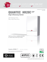
FIGURE 1. QUANTEC HR & COMBI USER CONTROL PANEL
4. BOILER CONTROL PANEL
TIME CONTROL
(Optional)
DOMESTIC
HOT WATER
TEMPERATURE
LCD
DISPLAY
CENTRAL
HEATING
TEMPERATURE
FUNCTION
MODES
RESET
BUTTON
INSTALLER
MODE
K7 K1
K6 K2
K3 K5
K4
ITEM DESCRIPTION
K1 CH - Central Heating +
K2 CH - Central Heating -
K3 Installer information
K4 Reset
K5 Summer/Winter mode
K6 DHW - Domestic Hot Water -
K7 DHW - Domestic Hot Water +
Showing standby mode
{
{
{

5
Sales/Spares 01604 707012 Replacement Help Line 01604 707011
5. TO LIGHT THE BOILER
5.1 Switch the mains power ON and the boiler LCD display will show “AP”. This puts the
boiler into the Air Purge Mode. See Figure 2.
5.2 Press the reset button “K4” twice. The boiler will go onto standby. See Figure 3. This is
the winter mode.
SETTING THE DHW WATER TEMPERATURE
5.3 To set the hot water temperature press and hold “K7”, this will flash until the °C
temperature shows. By pressing the + and - buttons to set the desired temperature. The
temperature flashes 5 times to set the temperature and then goes back onto standby.
SETTING THE CH WATER TEMPERATURE
5.4 To set the central heating temperature press and hold “K1”, this will flash until the °C
temperature shows. By pressing the + or - buttons to set the desired temperature.
The temperature flashes 5 time to set the temperature and the display will go back to
standby.
6. OPERATING FUNCTIONS
6.1 OPERATING THE DOMESTIC HOT WATER
When the hot water is called for by turning on the hot tap, the boiler will fire. The display
will show the full flame symbol, water temperature and flashing tap symbol, until the
hot tap is turned off and the display will return to standby or heating mode. See Figure
4.
Hot water has priority over central heating, so the central heating will stop while hot
water is being supplied
6.2 OPERATING THE CENTRAL HEATING
When there is a call for central heating the boiler will fire for 1 minute at low and then
will increase the modulation to match the demand for heating. The display will show
the flame symbol, water temperature and flashing radiator symbol, until the call for
central heating stops and the display will return to the standby mode. See Figure 5.
Approximate flow temperatures for the boiler thermostat settings are:
6.3 DISPLAY CODES
In normal operation the boiler LCD display will show:
1. Standby - no demand for heat. Figure 3.
2. CH being supplied. Figure 5.
3. DHW being supplied. Figure 4.
4. Boiler frost protection - boiler will fire if temperature is below 3°C.
5. During normal operation the burner on indicator will remain illuminated when the burner is lit.
Note: If the boiler fails to light after five attempts the fault code will be displayed. See trouble shooting.
6.4 TO SHUT DOWN THE BOILER
Set the mode to OFF by pressing K4.
To relight the boiler repeat the procedure detailed in ‘To light the boiler’.
6.5 FROST PROTECTION
If no system frost protection is provided and frost is likely during a short absence from home, leave the
heating controls (if fitted) at a reduced temperature setting. For longer periods, the entire system should be
drained.
If the system includes a frost thermostat then, during cold weather, the heating should be turned OFF at the
time switch (if fitted) ONLY. The mains supply should be left switched ON, with the boiler set to heating ON
and thermostat left in the normal running position.
FIGURE 2
FIGURE 3
FIGURE 4
FIGURE 5
TABLE. 2
Button Setting CH Flow Temperature
Minimum 40°C
Maximum
60°C

www.johnsonandstarley.co.uk
6
6.6 LOSS OF SYSTEM WATER PRESSURE
The pressure gauge indicates the central heating system pressure. If the pressure is seen to fall below the
original installation pressure of 1-2 bar over a period of time then a water leak may be indicated. In this event
conduct the re-pressurising procedure. If unable to do so or if the pressure continues to drop a Gas Safe
Registered Engineer or in IE a Registered Gas Installer (RGII) should be consulted.
6.6.1 HOW TO RE-PRESSURISE
The boiler will not operate if the pressure has reduced to less than 0.3 Bar under this condition.
1. Ensure filling loop isolation valves are closed.
2. Remove the two caps
3. Attach on the filling loop.
4. Turn the filling loop isolation valves to the open position. The system will now fill.
5. Wait for pressure gauge dial to reach 1 to 1.5 bar.
6. Close the filling loop isolation valves.
7. Disconnect the filling loop at left hand side and angle upwards.
8. Attach the two blanking caps.
6.7 CONDENSATE DRAIN
The condensate drain must not be modified or blocked.
Blockage of the condensate drain, caused by debris or freezing, can cause automatic shutdown of the
boiler.
If freezing is suspected and the pipe run is accessible an attempt may be made to free the obstruction by
pouring hot water over the exposed pipe and clearing any blockage from the end of the pipe. If this fails to
remedy the problem the assistance of a Gas Safe Registered Engineer or in IE a Registered Gas Installer
(RGII) should be sought.
7. RESET THE BOILER
Press the reset button “K4” twice.
8. SERVICING & MAINTENANCE
It is recommended that a full maintenance check be carried out annually on the appliance. It is also
recommended to take out a further service agreement on the expiry of the guarantee period.
You can obtain further information on this from your gas supplier.
The appliance should be checked /serviced by a GAS SAFE registered installer.
If you require service on your appliance please contact your local installer or gas supplier.
On completion of the service the installer should fill in the service section at the rear of the BENCHMARK
Checklist. All installers registered with GAS SAFE carry an identification card. This card will have an ID
number which should be recorded in your logbook.
If you have any queries regarding your installer you can contact GAS SAFE by
telephone on 0800 408 5500.
The appliance should be serviced at least once a year by a Gas Safe Registered
Engineer or in IE a Registered Gas Installer (RGII).
9. CLEANING
For normal cleaning simply dust with a dry cloth.
To remove stubborn marks and stains, wipe with a damp cloth and finish off with a dry cloth.
DO NOT use abrasive cleaning materials.
10. ESCAPE OF GAS
Should a gas leak or fault be suspected contact the National Gas Emergency Service without delay.
Telephone 0800 111 999 .

7
Sales/Spares 01604 707012 Replacement Help Line 01604 707011
ERROR CODES
E01
Ignition lockout
Check other gas appliances work
Reset boiler
Contact installer
E02
False flame lockout Contact installer
E03
Overheat lockout
Fill system to 1.0bar
Bleed radiators
Check radiator valves are open
Reset boiler
Contact installer
E05
Fan fault Contact installer
E08
Flame circuit failure Contact installer
E09
Valve feed back ERROR Contact installer
E12
EEPROM lockout Contact installer
E15
Sensor drift lockout
Fill system to 1.0bar
Bleed radiators
Check valves are open
Reset boiler
Contact installer
E16
E17
E18
Sensor stuck lockout
Fill system to 1.0bar
Bleed radiators
Check valves are open
Reset Boiler
Contact installer
E21
ADC lockout Contact installer
E33
Return thermistor fault Contact Installer
E34
Low power supply lockout Contact installer or Electrician
E35
Flow thermistor fault Contact Installer
11. TROUBLE SHOOTING

www.johnsonandstarley.co.uk
8
FAULT CODES
F07
Exhaust sensor fault
Fill system to 1.0bar
Bleed radiators
Check radiator valves are open
Reset boiler
Contact installer
F13
Remote reset lockout
Turn power on and off
Press Reset
Contact installer
F37
Low water pressure
Fill system to 1.0bar
Bleed radiators
Check radiator valves are open
Reset boiler
Contact installer
F40
Water pressure too high
Check to see if the gauge is over 2.8bar
Bleed radiators
Reset boiler
Contact installer
F47
Water pressure sensor not connected Contact installer
F52
DHW sensor fault Contact installer
F53
Flue temperature sensor lockout Contact installer
F82
30C-SA
ONLY
Sprayaway condensate level alarm Contact installer
Central heating not working Press and hold K6 & K7 hot water buttons for 5 seconds until symbol
disappears

9
Sales/Spares 01604 707012 Replacement Help Line 01604 707011
12. ENERGY RATING ErP TECHNICAL DATA FICHE
Ecodesigns energy related products directive requires our appliance to be fully compliant with
the ErP regulations. Our unit has a label which shows the level of efficiency for the boiler, CO2 &
NOx emissions and db noise emissions. This will help the householder understand the energy
efficiency within the home and help reduce energy consumption.
This regulation covers all products used in the installation. Once an installation has
been completed the installer will supply a final label incorporating all the items used in
the install. It shows the details of the systems overall efficiency. For further information
about the ErP Directive visit the Johnson and Starley Ltd website or email our helpline on
EU Regulations No. 811/2013 and No. 812/2013 supplementing Directive 2010/30/EU.
TABLE 1. ErP TECHNICAL DATA HR28C
HR28CP
30C 30C-SA 24C
PRODUCT DATA SYMBOL
VALUE VALUE VALUE VALUE VALUE UNIT
Condensing boiler - Yes Yes Yes -
Low temperature boiler - No No No -
B11 Boiler - No No No -
Cogeneration space heater - No No No -
Combination Heater - Yes Yes Yes -
Rated heat output Prated 21 23 16 kW
Seasonal space heating energy efficiency ŊS94 94 94 %
Energy efficiency class - A -
USEFUL HEAT OUTPUT
At rated heat output and high temperature regime P421.4 23.4 16.3 kW
At 30% of rated heat output and low temperature regime P17.3 7.8 5.5 kW
USEFUL EFFICIENCY
At rated heat output and high temperature regime Ŋ487.9 87.9 88.8 %
At 30% of rated heat output and low temperature regime Ŋ198.8 99.1 98.9 %
AUXILLARY ELECTRICITY CONSUMPTION
At full load elmax 0.068 kW
At part load elmin 0.048 kW
In standby mode PSB 0.002 kW
OTHER ITEMS
Standby heat loss
PSB 0.099 kW
Ignition burner power consumption
Pign 0 kW
Sound power level indoors L
WA
45 dB
ADDITIONAL DATA FOR COMBINATION HEATERS
Declared load profile XL M XL M
Daily electricity consumption Q
elec
0.112 0.069 0.109 0.114 kWh
Annual electricity consumption AEC
24 15 24 25 kWh
Daily fuel consumption Q
fuel
21.03 6.98 22.59 7.65 kWh
Annual fuel consumption AFC
16.7 427 17.89 6.06 Gj
Water heating energy efficiency
Ŋwk 91.4 85 86.5 78 %
Water heating energy efficiency class
- A -
1. High temperature regime means 60°C return temperature at heater inlet and 80°C feed temperature at heater output.
2. Low temperature means for condensing boiler 30°C, for low temperature boilers 37°C and for other heaters 50°C return
temperature (at heater).

www.johnsonandstarley.co.uk
10
GAS
LEAK
1
13. KEEP YOURSELF SAFE
Throughout the year it’s important to make sure that your gas appliances, such as a warm air heater, gas fire, cooker
and boiler are working safely and correctly. Did you know Gas Safe Register is the only official list of engineers who
are legally allowed to do work on gas and the gas appliances in your home? By law, all gas engineers must be on
the Gas Safe Register. The Register is there to help protect you from unsafe gas work.
In the right hands, gas is safe, but badly fitted and poorly maintained appliances can cause gas leaks, fires,
explosions and carbon monoxide poisoning. Carbon monoxide is a highly poisonous gas. You can’t see it, taste it
or smell it, but it can kill quickly with no warning but a carbon monoxide alarm would give you piece of mind but is
no substitute for an annual service.
Make sure you get your gas appliances regularly serviced and safety checked every year, by a Gas Safe registered
engineer. Annual maintenance not only helps keep your heating and hot water working properly; it helps keep you
and your family safe. If you’re a tenant, your landlord must arrange this every 12 months and provide you with a
Landlord’s Gas Safety Record.
You can set a free reminder at www.StayGasSafe.co.uk and Gas Safe Register will text or email you when your
appliances are due their next check.
All Gas Safe registered engineers carry a Gas Safe Register ID card. Before any gas work is carried out always
check the card and make sure the engineer is qualified for the work you need doing. You can find this on the back
of the card.
YOUR 5 POINT CHECKLIST
Signs of
carbon
monoxide Headaches Nausea Dizziness Breathlessness Collapse Loss of
Consciousness
0800 408 5500
GAS
CHECKS
SMELL GAS CALL
Always ask your gas engineer for his
Gas Safe identication card..
Keep those cowboys OUT!
All of your gas appliances
need regular annual safety checks.
Failure to do so could be fatal for you and your family.
Keep them safe.
H
O
U
S
E
·
S
A
F
E
T
Y
·
A
L
A
R
M
S
For the safety of your family.
Alarms cost as little as £15
BEAT THE SILENT KILLER!
Your gas safe engineer.
ASK FOR
I.D.
2
3
4
5
For gas safety advice or to find and check an engineer visit the Gas Safe Register website at
www.GasSafeRegister.co.uk or call the free helpline on 0800 408 5500.

11
Sales/Spares 01604 707012 Replacement Help Line 01604 707011
14. HOW TO SAVE ENERGY
ELECTRICAL SAVINGS
1. Switch off appliances
which are not in use.
2. Unplug chargers and
adapters.
3. Don’t leave TV’s
Stereo’s etc. on stand-
by.
4. Turn off lights in rooms
not being used.
5. When cooking use a
lid on the pan to hold
in the heat and turn the
temperature down.
We all wish to make savings on our energy bills and at the same time be warm and cosy in our
homes. As fuels costs rise, having an efcient and cost effective heating system is vital. You have
made your rst step in reducing your carbon dioxide emissions now look at other ways to help you
make extra saving on those fuel bills. Here are a few ways which can help you make those savings.
WATER SAVINGS
1. Fit a water saving
shower head to save
energy.
2. Turn down the
temperature on your
washing machine and
only do a full load.
3. Fill up the dishwashers.
4. Make sure taps are
turned off and not
dripping - can waste
5,500 litres of water a
year.
5. Have a shower instead
of a bath and take
shorter showers.
6. Turn off the tap when
cleaning your teeth.
HEATING SAVINGS
1. Fit thermostatic radiator
valves to give you
better control. Make
your boiler provide heat
where you need it.
2. Turn the room
thermostat and radiator
thermostat down by 1˚
3. Close curtains at night
to cut down draughts
from the windows and
stop the heat escaping.
4. Insulation and draught-
proofing on windows
and doors.
5. Rooms which are not
in use, turn off the
radiator.
6. Do not cover or hang
curtains in front of the
radiators.

Johnson & Starley Ltd
Rhosili Road, Brackmills,
Northampton NN4 7LZ
Reception/Customer Service
01604 762881
Fax
01604 767408
Anniversary 1922 - 2012
In the interest of continuous development Johnson & Starley reserve the right to change specifications without prior notice.
/