Page is loading ...

DOLSL/DOLSLK
Part No: DOLSL / DOLSLK
V.4.6.17
USER MANUAL


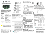
MOUNTING
1. Install the back plate on the wall as shown in the diagram
below.
2. The cover will clip on the upper edge. Push in the bottom part
as shown in the diagram.
3. Tighten the non-dropout screw, which is located underneath
the reader to fix the reader and the back plate. Installation is
complete.

Input Voltage (at
Reader end) DC9V~15V Typical Read
range > 5cm
Operating Current 120mA (max) Maximum Cable
Length 150m
Operating
Temperature -30ºC~70 ºC
1. Linear DC Power Supply
2. 22AWG shielded cable. It’s required to do “one-point”
ground (as shown in the diagram)
SPECIFICATIONS
RECOMMENDATION

Color Label Description
Red +12V dc Power Supply to the reader
Black GND Signal GND
Green Data0 Wiegand Output data, D0
White Data1 Wiegand Output data, D1
Yellow RED LED RED LED control, active low.
Blue Green LED Green LED control, active low
Brown Buzzer Buzzer input, active low
Orange Tamper Tamper output (open collector, Active low, max 100mA)
Purple Doorbell Door bell output (open collector, +5Vdc output ≤ 5mA)
WIRING
PHYSICAL DIMENSIONS

POWER UP SEQUENCES
1. This is a 125 KHz flash reader. When the reader is powered
up, the Green border will blink for 5 seconds. The reader will
beep once and is now in Ready mode.
2. Present the card. The Blue LED will blink once and the buzzer
will beep once.
3. When a card is presented and read by the reader, the card
data will be transmitted to the controller. Whether the back-lit of
the reader will remain ON, flash or change to Green or Red,
depends on the Green and Red LED inputs on the access
controller.
4. For the number pad reader, when a number is pressed and
succesfully detected, the back-lit LED under the number will
flash one time and the buzzer will beep once. The pin being
entered will output by default at a 4 bit burst.

Trouble List Solution
No Response
when Power Up
Disconnect the power and confirm that the power supply cable is
correctly connected (See “Wiring” above).
Check the input voltage is sufficient (See “Specifications” above).
Auto Restart Check that the input voltage is sufficient (See “Specifications” above).
Cannot read card
number correctly
Check the format setting on the controller if it is the same as the card
format. Use approved card (known format and Facility Code) to test.
Check if the shield cable is correctly connected to Ground at
ONE point only.
Reader beeps but
No card data info
Check if data 0 & data 1 cables are correctly connected (See “Wiring”
above).
Check the input voltage at the card reader is correct (See
“Specifications” above).
Buzzer error Check if the buzzer cable is correctly connected (See “Wiring” above).
Back Lit Error Check that the LED cable is correctly connected (See “Wiring” above).
Use Default Configuration Card to set it back to normal.
Keypad
No Response Power off reader for 5 seconds and power on again
TROUBLESHOOTING

The warranty period of Transmitter Solutions keypads are 24 months. This
warranty shall begin on the date the keypad is manufactured. During the
warranty period, the product will be repaired or replaced (at the sole
discretion of Transmitter Solutions) if the product does not operate correct-
ly due to a defective component. This warranty does not extend to (a) the
product case, which can be damaged by conditions outside the control of
Transmitter Solutions, or (b) battery life of the product. This warranty is
further limited by the following disclaimer of warranty and liability:
EXCEPT AS SET FORTH ABOVE, TRANSMITTER SOLUTIONS MAKES NO WARRANTIES
REGARDING THE GOODS, EXPRESS OR IMPLIED, INCLUDING WARRANTY OF
MERCHANTABILITY OR WARRANTY OF FITNESS FOR A PARTICULAR PURPOSE. BUYER
MAKES NO RELIANCE ON ANY REPRESENTATION OF TRANSMITTER SOLUTIONS,
EXPRESS OR IMPLIED, WITH REGARD TO THE GOODS AND ACCEPTS THEM
“AS-IS/WHERE-IS”. TRANSMITTER SOLUTIONS SELLS THE GOODS TO BUYER ON
CONDITION THAT TRANSMITTER SOLUTIONS WILL HAVE NO LIABILITY OF ANY KIND AS A
RESULT OF THE SALE. BUYER AGREES THAT TRANSMITTER SOLUTIONS SHALL HAVE
NO LIABILITY FOR DAMAGES OF ANY KIND, WHETHER DIRECT, INCIDENTAL OR CONSE-
QUENTIAL DAMAGES, INCLUDING INJURIES TO PERSONS OR PROPERTY, TO BUYER, ITS
EMPLOYEES OR AGENTS, AS A RESULT OF THE SALE. BUYER ALSO AGREES TO HOLD
TRANSMITTER SOLUTIONS HARMLESS FROM ANY CLAIMS BUYER, OR ANY THIRD
PARTY, MAY HAVE AS A RESULT OF BUYER’S USE OR DISPOSAL OF THE GOODS. BUYER
HAS READ THIS DISCLAIMER AND AGREES WITH ITS TERMS IN CONSIDERATION OF
RECEIVING THE GOODS.
2480 South 3850 West, Suite B Salt Lake City, UT 84120
(866) 975-0101 • (866) 975-0404 fax
www.transmittersolutions.com
WARRANTY
/


