Page is loading ...

iSMA CONTROLLI S.p.A. – Via Carlo Levi 52, 16010 Sant’Olcese (GE) - Italy |
support@ismacontrolli.com
www.ismacontrolli.com Installation Instruction| 3rd Issue rev. 3 | 01/2022 page 1
iSMA-B-8I
SPECIFICATION
Power supply
DC: 24 V ± 20%, 0.4 W; AC: 24 V ± 20%, 0.6 VA
Digital inputs
8x dry contact input, high-speed pulse counter up to 100 Hz
Interface
RS485 half-duplex: Modbus RTU/ASCII, up to 128 devices on the bus
Address
Set by switch in range from 0 to 99
Baudrate
Set by switch in range from 4800 to 115200 bps
Ingress protection
rating
IP40 - for indoor installation
Temperature
Operating: -10°C to +50°C (14°F to 122°F)
Storage: -40°C to +85°C (-40°F to 185°F)
Relative humidity
5 to 95% RH (without condensation)
Connectors
Separable, max 2.5 mm2 (18 – 12 AWG)
Dimension
37x110x62 mm (1.45x4.33x2.44 in)
Mounting
DIN rail mounting (DIN EN 50022 norm)
Housing material
Plastic, self-extinguishing PC/ABS
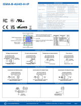
TOP PANEL
DIGITAL INPUTS
Dry contact
COMMUNICATION
POWER SUPPLY

iSMA CONTROLLI S.p.A. – Via Carlo Levi 52, 16010 Sant’Olcese (GE) - Italy |
support@ismacontrolli.com
www.ismacontrolli.com Installation Instruction| 3rd Issue rev. 3 | 01/2022 page 2
WARNING
TERMINALS OF THE DEVICE
• Note, an incorrect wiring of this product can damage it and lead
to other hazards. Make sure the product has been correctly wired
before turning the power ON.
• Before wiring, or removing/mounting the product, be sure to turn
the power OFF. Failure to do so might cause electric shock.
• Do not touch electrically charged parts such as the power
terminals. Doing so might cause electric shock.
• Do not disassemble the product. Doing so might cause electric
shock or faulty operation.
• Use the product within the operating ranges recommended in the
specification (temperature, humidity, voltage, shock, mounting
direction, atmosphere etc.). Failure to do so might cause fire or
faulty operation.
• Firmly tighten the wires to the terminal. Insufficient tightening of
the wires to the terminal might cause fire.
EN 60730-1 POWER SUPPLY CONSIDERATIONS
• Electrical safety in the building automation and control systems is essentially based on the use of extra low voltage which is strictly separated
from the mains voltage. This low voltage is either SELV or PELV according to EN 60730-1.
• Protection against electric shock is ensured by the following measures:
o limitation of voltage (low voltage AC/DC 24V supply, either SELV or PELV)
o protective-separation of the SELV-system from all circuits other than SELV and PELV
o simple-separation of the SELV-system from other SELV-systems, from PELV-systems and earth
• Field devices such as sensors, status contacts and actuators connected to the low-voltage inputs and outputs of I/O modules must comply with
the requirements for SELV or PELV. The interfaces of field devices and other systems must also satisfy SELV or PELV requirements.
• When the supply of SELV or PELV circuits is obtained from supply mains of higher voltages it shall be provided by safety transformer or a
converter designed for continuous operation to supply SELV or PELV circuits.
FCC COMPLIANCE NOTE
Note: This equipment has been tested and found to comply with the limits for a Class B digital device, pursuant to part 15 of the FCC Rules. These
limits are designed to provide reasonable protection against harmful interference in a residential installation. This equipment generates, uses and
can radiate radio frequency energy and, if not installed and used in accordance with the instructions, may cause harmful interference to radio
communications. However, there is no guarantee that interference will not occur in a particular installation. If this equipment does cause harmful
interference to radio or television reception, which can be determined by turning the equipment off and on, the user is encouraged to try to correct
the interference by one or more of the following measures:
• Reorient or relocate the receiving antenna.
• Increase the separation between the equipment and receiver.
• Connect the equipment into an outlet on a circuit different from that to which the receiver is connected.
• Consult the dealer or an experienced radio/TV technician for help.
WIRING
• Line power cables must be routed with spatial separation from signal and data transmission cables.
• Analogue and digital signal cables should also be separated.
• It is recommended to use shielded cables for analogue signals, cable shields should not be interrupted by intermediate terminals.
• The shielding should be earthed directly after the cable enters the cabinet.
• It is recommended to install interference suppressors when switching inductive loads (e.g. coils of contactors, relays, solenoid valves). RC
snubbers or varistors are suitable for AC voltage and freewheeling diodes for DC voltage loads. The suppressing elements must be connected as
close to the coil as possible
/