
GAGE BILT TOOLS ARE AVAILABLE WORLDWIDE
E-MAIL US FOR A DISTRIBUTOR NEAR YOU.
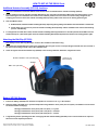
GB106 SERIES
16V BATTERY INSTALLATION TOOL
ORIGINAL INSTRUCTIONS
44766 Centre Court, Clinton Twp., MI. 48038 USA
Ph: +1 (586) 226-1500 Fax: +1 (586) 226-1505
[email protected] / www.gagebilt.com
GAGE BILT
MADE in USA
GB106 SERIES
GB106 Includes (1) VP1309 (2Ah Battery)
GB106/2 Includes (2) VP1309 (2Ah Batteries)
S/N: 1067 AND ABOVE
PLEASE CONTACT GAGE BILT FOR
ALL OTHER SERIAL NUMBERS.

2 7/21 REV 12/22
GB106 16V BATTERY INSTALLATION TOOL SN: 1067 AND ABOVE
PLEASE CONTACT GAGE BILT FOR ALL OTHER SERIAL NUMBERS.
TABLE OF CONTENTS
Page
Warranty ..................................................................................................................................................................................... 3
Description and Technical Specifications ............................................................................................................................... 4
Description of Functions ........................................................................................................................................................... 5
Warnings ..................................................................................................................................................................................... 6
Principle of Operation ................................................................................................................................................................ 7
How to set-up the GB106 ...................................................................................................................................................... 8-10
How to use the GB106 ............................................................................................................................................................. 11
Maintenance ............................................................................................................................................................................. 12
Troubleshooting ....................................................................................................................................................................... 13
Parts Lists ................................................................................................................................................................................. 14
Alternate Tools / Accessories ................................................................................................................................................. 16

3 7/21 REV 12/22
GB106 16V BATTERY INSTALLATION TOOL SN: 1067 AND ABOVE
PLEASE CONTACT GAGE BILT FOR ALL OTHER SERIAL NUMBERS.
Seller warrants that all goods covered by this catalog will conform
to applicable specifications and will replace or repair, EXW our plant, any
goods providing defective from faulty workmanship, or material, for 1 year
from date of shipment.
Said warranty to remain in effect if, and only if, such goods are
used in accordance with all instructions as to maintenance, operation and
use, set forth in manuals and instruction sheets furnished by seller.
Sellers obligation under this warranty shall be limited to the repair
or rework of the goods supplied or replacement thereof, at Seller’s option,
and in no case is to exceed the invoice value of said goods. Under no
circumstances will the seller be liable for incidental or consequential
damages or for damages incurred by the buyer or subsequent user in
repairing or replacing defective goods or if the goods covered by this
warranty are reworked or subjected to any type of additional processing.
This warranty is void if Seller is not notified in writing of any
rejections or defects within 1 year after the receipt of the material by the
customer.
THIS WARRANTY IS MADE IN LIEU OF ALL OTHER WARRANTIES
EXPRESSED OR IMPLIED, INCLUDING MERCHANTABILITY.
WARRANTY

4 7/21 REV 12/22
GB106 16V BATTERY INSTALLATION TOOL SN: 1067 AND ABOVE
PLEASE CONTACT GAGE BILT FOR ALL OTHER SERIAL NUMBERS.
SPECIFICATIONS
Weight (Incl. battery) - 3.9 lbs. (1.8 kg)
Drive (DC / BLDC) - DC
Sound Emissions - <65 / 3 // <76 / 3
(LpA / K // LWA / K [dB]
Vibrations ah / K [m/s2] - <2.5 / 1.5
Service interval (# of fasteners) - 100,000
Total Stroke - .827" (21 mm)
Rated Pull Load - 2,248 lbs. (10 kN)
Battery [ V ] - 16
Battery [ Ah ] - N/A
Battery Cells (Number) - 4
Battery weight - .32 lbs. (0.145 kg)
Battery working temp. [ °F-°C ] - 23°F - 113°F (-5°C - 45°C)
Charger Input Voltage [ V AC / Hz ] - 100 to 240 / 50 to 60
Charger Output Voltage [ V DC ] - 7.0 to 21.0
Charger Output Current [ Ah ] - 4
Charger Working Temp. [ °F-°C ] - 32°F - 104°F (0°C - 40°C)
Charger charging time to - 22 / 30 minutes
90% / 100%
Charger weight w/o cable - .55 lbs. (0.25 kg)
ENVIRONMENTAL USE
WARNING: Do not operate in an explosive atmosphere.
The GB106 can be operated between 23°F - 113°F (-5°C - 45°C)
DESCRIPTION
WARNING: Any other use is forbidden.
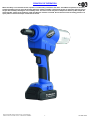
The GB106 is a battery operated 16V installation tool designed specifically for the efficient installation of 3/32” (3.9 mm) thru 3/16” (4.8 - 5.0 mm)
blind rivets. It weighs just 3.9 lbs. (1.8 kg) and can be operated in any position. It has a .827” (21 mm) fastener setting stroke and a rated pull
load of 2,248 lbs. (10 kN).
2.992 (76 mm)
2.600 (66 mm)
10.835 (275 mm)

5 7/21 REV 12/22
GB106 16V BATTERY INSTALLATION TOOL SN: 1067 AND ABOVE
PLEASE CONTACT GAGE BILT FOR ALL OTHER SERIAL NUMBERS.
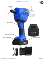
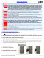
DESCRIPTION OF FUNCTIONS
Images may not reflect actual tool
Nose Tip
Mandrel Collection Bottle
Actuator Assembly
Riveting Point Light (white LED)
Battery Lock / Release Latch
Hanger Hole
Battery with charging
status indication
Universal Quick Charger
Nose Assembly

6 7/21 REV 12/22
GB106 16V BATTERY INSTALLATION TOOL SN: 1067 AND ABOVE
PLEASE CONTACT GAGE BILT FOR ALL OTHER SERIAL NUMBERS.
SAFETY WARNINGS
GENERAL SAFETY RULES:
1. For multiple hazards, read and understand the safety instructions before installing,
operating, repairing, maintaining, changing accessories on, or working near the
assembly power tool for non-threaded mechanical fasteners.
2. Only qualified and trained operators should install, adjust or use the assembly power
tool for non threaded mechanical fasteners.
3. Do not modify this assembly power tool for non-threaded mechanical fasteners. Modifications can
reduce effectiveness of safety measures and increase the risks to the operator.
4. Do not discard safety instructions; give them to the operator.
5. Do not use assembly power tool for non-threaded mechanical fasteners if it has been damaged.
6. Tools shall be inspected periodically to verify all ratings and markings required are
legible. The employer/user shall contact the manufacturer to obtain replacement
marking labels when necessary.
PROJECTILE HAZARDS:
1. Disconnect the tool from the energy source when changing inserted tools/nose as-
semblies or accessories.
2. Be aware that failure of the workpiece or accessories, or even the inserted tool/nose
assembly itself can generate high-velocity projectiles.
3. Always wear impact resistant eye protection during operation of the tool. The grade of
protection required should be assessed for each use.
4. The risk to others should also be assessed at this time.
5. Ensure that the workpiece is securely fixed.
6. Check that the means of protection from ejection of fastener and/or stem is in place
and operative (such as the deflector or collection bottle).
7. If the mandrel collecting containers can be fitted, ensure they are properly connected
and used correctly. By-passing of the safety switch is prohibited.
8. Forcible ejection of the mandrel from the front of the nose assembly is possible.
ELECTRICAL HAZARDS:
1. The plug must not be altered in any way. Do not use adapter plugs in conjunction with
earthed fast chargers.
2. Avoid physical contact with ungrounded surfaces, such as pipes, heaters, cookers or
refrigerators.
3. Keep installation tools away from water or rain. The ingress of water into the installation
tool increases the risk of electrical shock.
3. Do not misuse the cable, e.g. for carrying or hanging the fast charger or for pulling the
plug out of the socket. Keep the cable away from heat, oil, sharp edges or moving
parts. Damage or twisted cables increase risk of electric shock.
4. When using the installation tool outdoors, use for the fast charger only extension
cords that are also suitable for outdoor use. This will reduce risk of electric shock.
5. If the use of the installation tool in a damp environment is unavoidable, use for the fast
charger a residual current circuit breaker to avoid risk of shock.
6. The plug of the setting tool must fit properly into the plug socket. Modified plugs and
non matching plug sockets increase the risk of an electric shock.
OPERATING HAZARDS:
1. Use of tool can expose the operator’s hands to hazards, including crushing, impacts,
cuts, abrasions and heat. Wear suitable gloves to protect hands.
2. Operators and maintenance personnel shall be physically able to handle the bulk,
weight and power of the tool.
3. Hold the tool correctly; be ready to counteract normal or sudden movements and
have both hands available.
4. Maintain a balanced body position and secure footing.
5. Release the start-and-stop device in the case of interruption of energy supply.
6. Use only lubricants recommended by the manufacturer.
7. Avoid unsuitable postures as it is likely for these positions not to allow counteracting
of normal or unexpected movement of the tool.
8. If the tool is fixed to a suspension device, make sure that fixation is secure.
9. Beware of the risk of crushing or pinching if nose equipment is not fitted.
10. Due to the tool weight, it is recommended safety shoes be worn during operation.
11. It is recommended tool be operated not more than 50 out of every 60 minutes, where
prolonged use is expected.
REPETITIVE MOTIONS HAZARDS:
1. When using the tool, the operator can experience discomfort in the hands, arms,
shoulders, neck or other parts of the body.
2. While using the tool, the operator should adopt a comfortable posture while maintaining
a secure footing and avoiding awkward or off balanced postures. The operator should
change posture during extended tasks; this can help avoid discomfort and fatigue.
3. If the operator experiences symptoms such as persistent or recurring discomfort, pain,
throbbing, aching, tingling, numbness, burning sensations or stiffness, these warning
signs should not be ignored. The operator should tell the employer and consult a
qualified health professional.
ACCESSORY HAZARDS:
1. Disconnect tool from energy supply before changing the nose assembly or accessory.
2. Use only sizes and types of accessories recommended by the manufacturer. Do not
use other types or sizes of accessories.
WORKPLACE HAZARDS:
1. Do not work with the installation tool in a potentially explosive atmosphere where
there may be flammable liquids, gases or dusts. Installation tools generate sparks
that could ignite dusts or vapors.
2. Keep children and other persons away when working with the installation tool. If
distracted, you may lose control of the installation tool.
3. Do not use the installation tool when you are tired or under the influence of drugs,
alcohol or medication. Severe personal injury could result.
4. Be careful, pay attention to what you are doing and work sensibly when using the
installation tool.
NOISE HAZARDS:
1. Exposure to high noise levels can cause permanent, disabling hearing loss and other
problems, such as tinnitus (ringing, buzzing, whistling or humming in the ears). There-
fore, risk assessment and the implementation of appropriate controls for these haz-
ards are essential.
2. Appropriate controls to reduce the risk may include actions such as damping materials
to prevent workpieces from “ringing”.
3. Use hearing protection in accordance with employer's instructions and as required by
occupational health and safety regulations.
4. Operate and maintain the assembly power tool for non-threaded mechanical fasteners
as recommended in the instruction handbook, to prevent an unnecessary increase in
the noise level.
5. Select, maintain and replace the consumable/inserted tool as recommended in the
instruction handbook, to prevent an unnecessary increase in noise.
6. If the power tool has a silencer, always ensure that it is in place and in good working
order when the power tool is being operated.
VIBRATION HAZARDS:
1. Exposure to vibration can cause disabling damage to the nerves and blood supply of
the hands and arms.
2. Wear warm clothing when working in cold conditions and keep your hands warm and dry.
3. If you experience numbness, tingling, pain or whitening of the skin in your fingers or
hands, stop using the assembly power tool for non-threaded mechanical fasteners,
tell your employer and consult a physician.
4. Support the weight of the tool in a stand, tensioner or balancer, because a lighter grip
can then be used to support the tool.
TERMS AND SYMBOLS
- Product complies with requirements
- Hearing protection and eye protection
WARNINGS - Must be understood to avoid severe
personal injury.
CAUTIONS - show conditions that will damage
equipment and/or structure.
Notes - are reminders of required procedures.
- Read manual prior to using equipment
- Wear safety boots
- Product complies with requirements

7 7/21 REV 12/22
GB106 16V BATTERY INSTALLATION TOOL SN: 1067 AND ABOVE
PLEASE CONTACT GAGE BILT FOR ALL OTHER SERIAL NUMBERS.
PRINCIPLE OF OPERATION
When the battery is connected to the tool, operation is controlled by a actuator to the motor. The GB106 incorporates an electronic
actuator assembly to send a signal to the motor. When the actuator assembly is depressed, the gear on the motor spins the gear on
the gear box assembly retracting the nose assembly collet. This action causes the jaws to clamp on the fastener pintail and pull the
sheets together. Further force breaks the pintail off. When the actuator is released, the tool moves back to its starting position. The
spent pintail is released and drops out the back of the tool.

8 7/21 REV 12/22
GB106 16V BATTERY INSTALLATION TOOL SN: 1067 AND ABOVE
PLEASE CONTACT GAGE BILT FOR ALL OTHER SERIAL NUMBERS.
HOW TO SET-UP THE GB106
Universal Quick Charger (VP1087):
1. Connect the universal quick charger (VP1087) into a wall socket using the cable supplied.
2. Push the battery (VP1309) carefully and without force into the holder. Remove the battery (VP1309) the same way.
3. The universal quick charger (VP1087) charges the battery (VP1309) in 30 minutes; the battery is 90% charged after
approximately 22 minutes. Observe the corresponding indicators on the universal quick charger (VP1087).
4. The optimum charging and discharging temperature for the Li-Ion cells is 77°F (25°C). No complete
charging or discharging capacity can be reached above and below 77°F (25°C).
5. Use only the connecting cable supplied (with IEC power connector).
6. Use universal quick charger (VP1087) to charge only the batteries (or new ones) supplied with tool.
7. Charge only in a temperature range between 32°F - 104°F (0°C - 40°C).
WARNING: Only qualified and trained operators shall install, adjust or use the installation power tool for all fasteners.
WARNING: Operator MUST read and understand all warnings and cautions.
WARNING: It is required that eye protection, hearing protection and safety boots be worn at all times while handling this equipment.
WARNING: The users or the user’s employer must assess specific risks that could be present before each use based on their application.
● Ensure there is adequate clearance for tool and operator's hands before proceeding. Keep fingers clear of any
moving parts. Keep fingers clear from fasteners and installed materials. Severe personal injury may result.
● Ensure that there are no electrical cables, gas pipes, etc., which can cause a hazard if damaged by the tool.
WARNING: Do not actuate fastener in the air. Personal injury from fastener ejecting may occur.
WARNING: Do not use as a hammer. If improperly used or damaged, liquid can escape from the battery causing skin irritations
or burns. Wash with water or seek medical attention immediately if liquid gets into eyes or burns occur.
WARNING: Do not use in explosive atmosphere.
WARNING: Charge the batteries only in chargers recommended by the manufacturer. Risk of fire or explosion if batteries
used on non manufacturer chargers.
WARNING: Use only the specified batteries in the tool. The use of other batteries could result in injury or fire.
WARNING: Keep battery (VP1309), when not in use, away from paper clips, coins, keys, nails, screws, or other small metal
objects that could cause bridging of the contacts. A short circuit between the battery contact can cause burns or fire.
WARNING: Never operate the installation tool without the mandrel collection bottle (VP1002) or cover cap (VP1321).
WARNING: By-passing the safety switch is prohibited. Do not use if switch is defective or can no longer be turned on or off.
WARNING: Do not use cover cap (VP1321) with non self releasing nose assemblies. Damage to tool will occur.
WARNING: Ensure the mandrel collection bottle (VP1002) / cover cap (VP1321) are properly connected and used correctly.
WARNING: Avoid inadvertent starting of the installation tool.
WARNING: Having your finger on the actuator assembly (VP1316) while carrying the installation tool can lead to accidents.
CAUTION: Check that the hanger clip (VP1322) is securely fitted before using the tool. Ensure the clip is not stretched too
far apart and loses its tension.
CAUTION: Do not use beyond the design intent.
CAUTION: Remove the battery (VP1309) before making adjustments to the tool, changing accessories, or putting tool away.
This precautionary measure prevents any unintentional starting of the installation tool.
Charging the Battery (VP1309):
Note: The battery (VP1309) is partially charged on delivery.
1. In order to ensure the full performance of the battery (VP1309), charge the battery (VP1309) completely
before the first use. Observe the notes on the state of charge on the universal quick charger (VP1087).
2. The Li-Ion battery (VP1309) can be recharged at any time without shortening its service life.
3. Interruptions of the charging cycle does not damage the battery (VP1309).
4. The charger (VP1087) is equipped with a temperature monitoring device that permits charging only in
the temperature range between 32°F - 104°F (0°C - 40°C).

9 7/21 REV 12/22
GB106 16V BATTERY INSTALLATION TOOL SN: 1067 AND ABOVE
PLEASE CONTACT GAGE BILT FOR ALL OTHER SERIAL NUMBERS.
HOW TO SET-UP THE GB106 Cont.
Battery (VP1309):
1. Always make removing the battery (VP1309) from the installation tool your first step before making adjustments, changing parts or
overhauling and installing the battery (VP1309) into the tool your last step before using to prevent accidental starting of the tool.
2. The battery (VP1309) has a latch on the front side. To insert or remove the battery, press the latch downwards and push the
battery (VP1309) into the installation tool foot or pull it out.
3. Use the battery (VP1309) in the installation tool only in the specified temperature range 23°F - 113°F (-5°C - 45°C).
4. Charge the battery (VP1309) only in a temperature range between 32°F - 104°F (0°C - 40°C).
5. Use only an approved charger.
6. Never short-circuit the battery (VP1309).
7. If the battery (VP1309) shows signs of visible damage, no not use it any longer and dispose of it in a proper manner.
8. Keep the battery (VP1309) away from moisture and liquids.
Safety Switch
Cover Cap (VP1321)
Images may not reflect actual tool
Preparing the Installation Tool (GB106):
1. Attach the mandrel collection bottle (VP1002) by turning to the right.
Note: Tool will not function without mandrel collection bottle (VP1002) or cover cap (VP1321)
attached. (See safety switch below).
2. Push the battery (VP1309) into the foot of the installation tool from the front and ensure it is
properly engaged.
Safety Switch:
1. This installation tool is equipped with a safety switch in the rear of installation tool and thus conforms to the Machinery Directive.
This prevents the installation tool from being used without the mandrel collection bottle (VP1002) or cover cap (VP1321).
2. Never bypass the safety switch.
3. Never operate the tool without the mandrel collection bottle (VP1002) or cover cap (VP1321).
4. If you have to work in confined spaces, the cover cap (VP1321) can be used instead of the mandrel collection bottle (VP1002).
5. When working with the cover cap (VP1321), hold the installation tool with the anvil insert facing downwards after each set fastener
to ensure that the sheared mandrel drops out of the tool to the front.
6. Do not use cover cap (VP1321) with non-self releasing nose assemblies. This would result in damage to the installation tool.

10 7/21 REV 12/22
GB106 16V BATTERY INSTALLATION TOOL SN: 1067 AND ABOVE
PLEASE CONTACT GAGE BILT FOR ALL OTHER SERIAL NUMBERS.
Additional Actuator Assembly (VP1316) functions:
Note: The installation tool has two additional functions that are controlled with the actuator assembly (VP1316).
1. Service position: Press the actuator assembly (VP1316) for five seconds (until the white LED on the tool starts to flash (1 /sec)
and release again. The installation tool remains in the rearmost position. The anvil insert can now be easily changed or the
clamping jaws serviced. Press the actuator assembly (VP1316) briefly and the tool moves to its starting position again.
2. Auto and Manual mode:
a. In Manual mode, hold the actuator assembly (VP1316), depressing during setting of the fastener until the mandrel is sheared off.
b. In Auto mode, you only have to press the actuator assembly (VP1316) briefly and the installation tool controls the fastening
process automatically.
3. To change from one mode to the other, hold the actuator assembly (VP1316) pressed for ten seconds (until the white LED on the tool
starts to flash (2 sec.) and release again. Press the actuator assembly (VP1316) briefly and the tool moves to its starting position again.
HOW TO SET-UP THE GB106 Cont.
BELT CLIP (VP1322)
SCREW
SLOTS FOR BELT CLIP (VP1322) (2X) Image may not
reflect actual tool
Battery (VP1309) Storage:
1. Protect the battery (VP1309) from moisture and liquids. Do not leave in car e.g. in the summer.
2. Store the battery (VP1309) only in optimum temperature range between -22°F (-30°C) and 77°F (25°C). The batteries can be stored
as follows without recharging:
Storage period between 22°F (-30°C) and 77°F (25°C) = 1.5 years
Storage period between 22°F (-30°C) and 113°F (45°C) = 3 months
Storage period between 22°F (-30°C) and 140°F (60°C) = 1 month
3. A significantly shorter operating time after recharging indicates that the battery (VP1309) is worn out and needs to be replaced.
Observe all local disposal procedures.
Attaching the Belt Clip (VP1322):
Note: Always ensure belt clip (VP1322) is secure to the installation tool before using.
1. Attach the belt clip (VP1322) to the foot of the installation tool using the screw. A corresponding thread and slots are recessed in
the foot of the housing on both sides of the installation tool.
2. Check at regular intervals that the belt clip (VP1322) is still securely attached. Otherwise, retighten the screw.

11 7/21 REV 12/22
GB106 16V BATTERY INSTALLATION TOOL SN: 1067 AND ABOVE
PLEASE CONTACT GAGE BILT FOR ALL OTHER SERIAL NUMBERS.
HOW TO USE THE GB106
Blind Fasteners
1. Insert fastener into workpiece.
2. Insert fastener into nose assembly.
3. Press actuator to start cycle.
4. Release actuator as soon as fastener breaks.
5. Repeat steps 1-4.
Images may not reflect actual tool or fastener
Working with the Installation tool (GB106):
1. Insert the mandrel of the fastener into the nose assembly.
Note: Tool will not function without the mandrel collection bottle (VP1002) or cover cap (VP1321) attached.
2. Now insert the fastener into the parts to be fastened. For a good fastening result, ensure that the parts and head of the fastener
are resting on one another without a gap.
3. Press the actuator assembly (VP1316) until the mandrel is sheared.
4. Hold the installation tool so that the mandrel collection bottle (VP1002) is facing downwards to ensure that the sheared mandrel
drops into the mandrel collection bottle (VP1002).
5. When working with the cover cap (VP1321), hold the installation tool with the nose assembly facing downwards after each set
fastener to ensure that the sheared mandrel drops out of the installation tool to the front. DO NOT use cover cap (VP1321) with
non self releasing nose assemblies. This would result in damage to the tool.
WARNING: Only qualified and trained operators shall install, adjust or use the installation power tool for all fasteners.
WARNING: Operator MUST read and understand all warnings and cautions.
WARNING: It is required that eye protection, hearing protection and safety boots be worn at all times while handling this equipment.
WARNING: The users or the user’s employer must assess specific risks that could be present before each use based on their application.
● Ensure there is adequate clearance for tool and operator's hands before proceeding. Keep fingers clear of any
moving parts. Keep fingers clear from fasteners and installed materials. Severe personal injury may result.
● Ensure that there are no electrical cables, gas pipes, etc., which can cause a hazard if damaged by the tool.
WARNING: Do not actuate fastener in the air. Personal injury from fastener ejecting may occur.
WARNING: Do not use as a hammer. If improperly used or damaged, liquid can escape from the battery causing skin irritations
or burns. Wash with water or seek medical attention immediately if liquid gets into eyes or burns occur.
WARNING: Do not use in explosive atmosphere.
WARNING: Charge the batteries only in chargers recommended by the manufacturer. Risk of fire or explosion if batteries
used on non manufacturer chargers.
WARNING: Use only the specified batteries in the tool. The use of other batteries could result in injury or fire.
WARNING: Keep battery (VP1309), when not in use, away from paper clips, coins, keys, nails, screws, or other small metal
objects that could cause bridging of the contacts. A short circuit between the battery contact can cause burns or fire.
WARNING: Never operate the installation tool without the mandrel collection bottle (VP1002) or cover cap (VP1321).
WARNING: By-passing the safety switch is prohibited. Do not use if switch is defective or can no longer be turned on or off.
WARNING: Do not use cover cap (VP1321) with non self releasing nose assemblies. Damage to tool will occur.
WARNING: Ensure the mandrel collection bottle (VP1002) / cover cap (VP1321) are properly connected and used correctly.
WARNING: Avoid inadvertent starting of the installation tool.
WARNING: Having your finger on the actuator assembly (VP1316) while carrying the installation tool can lead to accidents.
CAUTION: Check that the hanger clip (VP1322) is securely fitted before using the tool. Ensure the clip is not stretched too
far apart and loses its tension.
CAUTION: Do not use beyond the design intent.
CAUTION: Remove the battery (VP1309) before making adjustments to the tool, changing accessories, or putting tool away.
This precautionary measure prevents any unintentional starting of the installation tool.

12 7/21 REV 12/22
GB106 16V BATTERY INSTALLATION TOOL SN: 1067 AND ABOVE
PLEASE CONTACT GAGE BILT FOR ALL OTHER SERIAL NUMBERS.
DAILY MAINTENANCE
WARNING: Do not use tool if switch is defective.
WARNING: Keep installation tool out of the reach of children when not in use.
WARNING: Maintenance personnel MUST read and understand all warnings and cautions.
WARNING: Disconnect battery before performing maintenance, cleaning or when replacing worn or damaged components.
Severe personal injury may occur if power source is not disconnected.
WARNING: Read SDS documents for all applicable materials.
WARNING: Installation tool must be repaired only by qualified specialist personnel and only with original spare parts. This
will ensure the safety of the installation tool is maintained.
The performance of any tool depends upon good maintenance practices. Following these minimal requirements daily will extend the
life of your tool.
* An installation tool that can no longer be switched on or off is dangerous and must be repaired.
* Maintain installation tools with care. Check that moving parts function correctly and do not jam.
* Check that parts are not broken or damaged in such a way that the function of the installation tool is impaired.
* Have damaged parts repaired before using the tool. Accidents are caused by poorly serviced tools.
* Use installation tool, accessories, attachments, etc. only as described in these instructions.
* Give consideration to the working conditions and the work to be carried out. The use of tools for other than intended applications
can lead to dangerous situations.
* Visual inspection of the installation tool should be done daily by the maintenance personnel.
* Battery charge state should be done daily by the maintenance personnel.
* Cleaning and lubricating the clamping jaws should be done between 1,000 and 10,000 fasteners depending on the fastener type, by
the maintenance personnel.
* Changing the jaws should be done by the maintenance personnel when the fastener can no longer be set in one stroke.
* Changing the anvil insert should be done by the maintenance personnel every 25,000 to 50,000 fasteners.
* Full inspection should be done every 300,000 fasteners or once a year by qualified trained maintenance personnel or by Gage Bilt.
Depending on the mandrel material, shear force and surface finish, the clamping jaws have to be cleaned and replaced at regular intervals.
CLEANING AND LUBRICATING THE CLAMPING JAWS
4. Clean the inside and outside of collet. Grease the inside lightly
with graphite grease using a brush.
5. Place jaw set into the collet.
6. Install collet with jaws back onto tool and reassemble nose
assembly per data sheet instructions.
Clean nose assembly daily or as often as needed.
1. Loosen and remove the anvil assembly using a combination
wrench.
2. Loosen and remove collet from adapter using two wrenches
and remove the 3 piece jaw set from the collet.
3. Clean jaws and inspect for wear. Replace if necessary.
Use a sharp “pick” to remove embedded particles from
grooves of jaws.
Battery Disposal:
1. Do not throw the battery (VP1309) into the domestic waste, fire or water.
2. Batteries/ rechargeable batteries are collected and recycled or disposed of in an eco-friendly manner.
For EU countries only:
1. In accordance with Directive 91/157/EEC, defective old batteries must be recycled. Batteries that can no longer be used can be
returned to your dealer.
Disposal of Installation Tool and Quick Charger:
1. Installation tools, chargers, accessories and packaging's should be recycled in an eco-friendly manner.
2. Do not throw tools into the domestic waste.
For EU countries only:
1. In accordance with European Directive 2002/96/EC on Waste Electrical and Electronic Equipment and implementation in national
law, Installation tools must be collected separately and recycled in an eco-friendly manner at the end of the useful life.

13 7/21 REV 12/22
GB106 16V BATTERY INSTALLATION TOOL SN: 1067 AND ABOVE
PLEASE CONTACT GAGE BILT FOR ALL OTHER SERIAL NUMBERS.
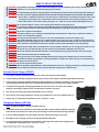
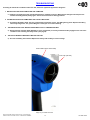
TROUBLESHOOTING
Providing all maintenance conditions have been met, follow this systematic approach to diagnosis.
1. INSTALLTION TOOL STOPS AND A RED LED COMES ON.
a.) Fasteners are used beyond the specified performance capability of the tool. Wait until the LED goes out and press the
actuator assembly (VP1316) briefly again. The tool then moves to its starting positions.
2. THE INSTALLATION TOOL COMPLETES THE CYCLE THEN STOPS.
a.) The battery (VP1309) is dead. The tool is protected by a protection circuit. The LED lights up yellow. Replace the battery
with a fully charged one. The yellow LED goes out and you can continue working.
3. THE INSTALLATION TOOL DOESN’T WORK WITH A FULLY CHARGED BATTERY.
a.) Ensure mandrel collection bottle (VP1002) or cover cap (VP1321) is securely mounted and fully engaged in the rear of the
installation tool activating the safety switch. (See page 9).
4. THE LED FLASHES ALTERNATELY RED AND YELLOW.
a.) An incorrect battery was installed. Replace the battery with a battery of correct voltage.
Fault Indicator (Red / Yellow LED)
Cover Cap (VP1321)
Image may not reflect actual tool

14 7/21 REV 12/22
GB106 16V BATTERY INSTALLATION TOOL SN: 1067 AND ABOVE
PLEASE CONTACT GAGE BILT FOR ALL OTHER SERIAL NUMBERS.
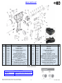
GB106 PARTS LIST
GB106 SHOWN ABOVE
GB106 SERIES
GB106 Includes (1) VP1309 (2Ah Battery)
GB106/2 Includes (2) VP1309 (2Ah Batteries)
23a 23b
REF NO. PART NO. DESCRIPTION QTY. REF NO. PART NO. DESCRIPTION QTY.
1 VP1030 SPACER 1 16 VP1320 MOTOR 1
2 VP1311 SCRAPER 1 17 VP1321 COVER CAP 1
3 VP1033 EXTENSION SLEEVE 1 18 VP1322 BELT CLIP 1
4 VP1019 GUIDE SLEEVE 1 19* VP1323 NAME PLATE 1
5 VP1031 CLAMPING JAWS (1 SET=3 PIECES) 1 20 VP1032 MANDREL DISCHARGE TUBE 1
6 VP1020 CLAMPING SLEEVE 1 21 VP1021 PRESSURE SPRING 1
7 VP1010 FRONT SLEEVE 1 22 VP1018 PLASTIC TUBE 1
8a VP1048 STANDARD NOSEPIECE 2.4mm 1 23a VP1002 MANDREL CONTAINER L (8.0 CM) 1
8b VP1049 STANDARD NOSEPIECE 3.0/3.2mm 1 23b* VP1324 MANDREL CONTAINER S (5.5 CM) 1
8c VP1050 STANDARD NOSEPIECE 4mm 1 24 VP1488 MANDREL SAFETY SWITCH - COVER PLATE 1
8d VP1051 STANDARD NOSEPIECE 4.8/5mm 1 25 VP1429 MANDREL SAFETY SWITCH-LEVER & SPRING 1
9 VP1572 TRIGGER AND PRESSURE SPRING 1 26 VP1430 MANDREL SAFETY SWITCH-SWITCH & CABLE 1
10 VP1317 HANGER 1 27 VP1004 MAGNET HOLDER WITH MAGNET 1
11 VP1007 SCREW FOR BEARING (1 SET = 2 PIECES) 1 28 VP1325 GEAR BOX COMPLETE 1
12 VP1003 GEAR BOX BEARING 1 29a VP1309 Li-ion RivdomPLUS BATTERY 16V/2.0Ah 1
13 VP1011 HOUSING SCREWS (1 SET = 10 PIECES) 1 29b* VP1310 Li-ion Rivdom PLUS BATTERY 16V/4.0Ah 1
14 VP1318 HOUSING (LEFT AND RIGHT) 1 30 VP1087 UNIVERSAL QUICK CHARGER 110V 1
15 VP1319 ELECTRONIC ASSEMBLY COMPLETE 1 No Fig. VP1327 SCREW FOR ELEC. ASSY 1
* Sold Separately

15 7/21 REV 12/22
GB106 16V BATTERY INSTALLATION TOOL SN: 1067 AND ABOVE
PLEASE CONTACT GAGE BILT FOR ALL OTHER SERIAL NUMBERS.
This page intentionally left blank

16 7/21 REV 12/22
GB106 16V BATTERY INSTALLATION TOOL SN: 1067 AND ABOVE
PLEASE CONTACT GAGE BILT FOR ALL OTHER SERIAL NUMBERS.
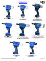
Alternate Tools
(Sold Separately)
GB101
Blind rivets 3/32” (2.4 mm) thru
5/32” (4.0 mm) diameter.
GB110A
Blind rivets 3/32” (2.4 mm) thru 1/4” (6.3 mm)
& specific 5/16” (7.9 mm) diameter.
Lockbolts 5/32” (3.9 mm) thru 1/4” (6.3 mm).
Contact Gage Bilt for nose
assembly options.
GB108
Blind rivets 3/32” (2.4 mm) thru
1/4” (6.3 mm) diameter.
GB128
1/4” (6.3 mm) thru
5/16” (7.9 mm) diameter
seal plug.
GB116RN
Rivet nuts M4-M10, M3/M12 Optional,
Rivet studs M4-M8
Process Monitoring
GB101S
Blind rivets 3/32” (2.4 mm) thru
5/32” (4.0 mm) diameter.
Process Monitoring.
GB108A
Blind rivets 3/32” (2.4 mm) thru
1/4” (6.3 mm) diameter. Contact
Gage Bilt for nose assembly options.
GB101A
Pulls a variety of small diameter
aerospace fasteners.
Contact Gage Bilt for nose
assembly & fastener options.
-
 1
1
-
 2
2
-
 3
3
-
 4
4
-
 5
5
-
 6
6
-
 7
7
-
 8
8
-
 9
9
-
 10
10
-
 11
11
-
 12
12
-
 13
13
-
 14
14
-
 15
15
-
 16
16


Ask a question and I''ll find the answer in the document
Finding information in a document is now easier with AI
Related papers
Other documents
-
 Performance Tool W9069 Rivet Gun Drill Adapter Owner's manual
-
 NIPPON POP RIVETS AND FASTENERS PNT1000 User manual
-
Nordic POBA3840 User manual
-
-
 Golden Technologies GB106XR User manual
-
 Golden Technologies GB106XR User manual
-
 Golden Technologies Buzzaround Lite User manual
-
 Golden Technologies Buzzaround Lite User manual
-
 Golden Technologies Buzzaround XL GB146 User manual
-
Metabo NMP 18 LTX BL M10 Cordless Rivet Nut Gun User manual


