Page is loading ...

Installation Guide
TracNet™
H60


© 2022-2023 KVH Industries, Inc., All rights reserved. 54-1403 Rev. C 1
TracNet™ H60
Installation Guide
This guide explains how to install the TracNet H60 hybrid VSAT, cellular, and Wi-Fi communications system. Operation
instructions are provided in the Quick Start Guide.
Table of Contents
Important Safety Information............................................. 2
Inspect Parts and Get Tools.............................................. 3
Plan the Antenna Installation ............................................. 4
Plan the BDU Installation................................................... 7
Prepare the Antenna Site .................................................. 8
Remove Shipping Restraints ............................................. 9
Prepare the Antenna Cable ............................................. 10
Wire the Antenna ............................................................. 11
Mount the Antenna .......................................................... 12
Mount the BDU (Hub+ Option) ........................................ 13
Mount the BDU (Hub Option) .......................................... 14
Wire the BDU................................................................... 15
Connect an NMEA Talker ................................................ 16
Connect Power (Hub+ Option) ........................................ 17
Connect Power (Hub Option) .......................................... 19
Turn On the System......................................................... 20
Configure the System...................................................... 21
No-Transmit Zones (Optional)..........................................27
Test the System ...............................................................28
Connect Vessel Network Devices....................................29
Connect the Vessel Phones .............................................30
Add Third-party SIM (Optional) ........................................31
Add Backup or Alternate WAN Connection (Optional) ....34
Educate the Customer .....................................................35
Appendices
Terminating LMR-240 Cable............................................36
Connecting Pigtail Cables to the Antenna Cable.............40
Approved Cable Types ....................................................41
Verifying the NMEA 0183 Message .................................42
Wiring Diagram (Hub+ Option) .........................................43
Wiring Diagram (Hub Option) ...........................................44
CAUTION - RF Radiation Hazard
The antenna transmits radio frequency (RF) energy
that is potentially harmful. Whenever the system is
powered on, make sure everyone stays more than
47.3 feet (14.4 m) away from the antenna. As
shown in the illustration, no hazard exists directly
below the antenna.
Who Should Install the System?
To ensure a safe and effective installation, only a KVH-
certified marine technician should install the system. To
find a technician near you, visit www.kvh.com/
wheretogetservice.
Technical Support
Within Continental U.S.A.: 1 866 701-7103
Worldwide: +1 401 851-3806
Email: [email protected]

TracNet H60 Installation Guide
2
Important Safety Information
Trademark Information
KVH, TracNet, KVH ONE, and the unique light-colored
dome with dark contrasting baseplate (Reg. No.
2,864,752) are trademarks of KVH Industries, Inc.
All other trademarks are the property of their respective
companies.
Disclaimer
Every effort has been made to ensure the correctness and
completeness of the material in this document. No
company shall be liable for errors contained herein. The
information in this document is subject to change without
notice. No warranty of any kind is made with regard to this
material, including, but not limited to, the implied
warranties of merchantability and fitness for a particular
purpose.
Feedback
If you have any comments regarding this manual, please
email them to [email protected]. Your input is greatly
appreciated!
Important Safety Information
This icon indicates a danger, warning, or caution
notice. Be sure to read these carefully to avoid
injury.
WARNING Risk of Electric Shock
If any component of the TracNet H60 system
becomes damaged and/or no longer functions
normally, disconnect it from vessel power,
secure it from unintended operation, and
contact KVH Technical Support (see
“Technical Support” on page 1). All repairs or
modifications must be performed by a trained,
KVH-certified technician. If you are a KVH-
certified technician, you still must contact KVH
Technical Support prior to conducting any
repairs or modifications to the equipment.
WARNING Risk of Explosion
Do not operate the TracNet BDU (or any other
electrical device) in an environment where
flammable gases, vapors, or dusts are present.
In addition, do not operate the unit in an
environment with a temperature outside its
5º F to 131º F (-15º C to 55º C) temperature
range.
CAUTION Risk of Electric Shock
Failure to ground the H60 system properly to
ship’s ground will cause an unsafe floating
ground condition, risking potentially lethal
electric shock. See “Connect Power (Hub+
Option)” on page 17 or “Connect Power (Hub
Option)” on page 19 for details on the proper
grounding of the equipment.
CAUTION RF Radiation Hazard
The antenna transmits up to 6 watts of radio
frequency (RF) energy that is potentially
harmful. Whenever the system is powered on,
make sure everyone stays more than 47.3 feet
(14.4 m) away from the antenna. No hazard
exists directly below the antenna.

3
TracNet H60 Installation Guide Inspect Parts and Get Tools
Inspect Parts and Get Tools
Before you begin, follow these steps to ensure you have
everything needed to complete the installation.
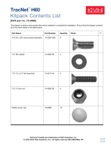
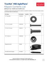
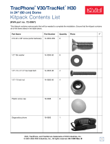
1. Unpack the box and ensure it contains everything
shown in Figure 1 and on the Kitpack Contents List.
Save the packaging for future use.
Figure 1: TracNet H60 System Components
Note: This manual refers to the TracNet Hub+ or Hub as
the BDU (Below Deck Unit).
2. Carefully examine all of the supplied parts to ensure
nothing was damaged in shipment.
3. Gather the following tools and materials:
• Flat-head and Phillips-head screwdrivers
• Electric drill and 5/8" (16 mm) bit
• Saw to cut cable access hole: either 5.5" (140 mm)
or 3.75" (95 mm) + 1.5" (38 mm)
• 5/16" hex driver (for mounting bolts) and 7/8" socket
or wrench (for mounting nuts); recommended
torque: 25-30 ft-lbs (34-41 N-m)
• Light hammer and center punch
• Adhesive tape
• Self-vulcanizing tape or equivalent
• Heat gun (for heat shrink)
• Eye protection
•Shop towels
• Voltmeter
• Utility knife
• Flush cutters
• File
• Wire stripper/terminal crimper
• Isolation transformer, if required (see “Connect
Power (Hub+ Option)” on page 17)
• Cable termination tools, if necessary (see “Prepare
the Antenna Cable” on page 10)
• NMEA 0183 or NMEA 2000 talker and interface
cable (see “Connect an NMEA Talker” on page 16)
• Laptop PC or Apple® or Android™ smartphone/
tablet with the latest H-series antenna software
downloaded from the KVH Partner Portal
(www.kvh.com/partners), or a smartphone/tablet
with the KVH Connect app installed and loaded with
the latest antenna software
IMPORTANT!
Always lift the antenna by the baseplate or hoisting
eyelets on the frame and never by the radome or any
other portion of the internal antenna assembly.
IMPORTANT!
Be sure to download the correct version of software for
the system’s BDU type:
Hub+ filename: Hxx_AC-BDU-<version no.>.bin
Hub filename: Hxx_DC-BDU-<version no.>.bin

TracNet H60 Installation Guide
4
Plan the Antenna Installation
Plan the Antenna Installation
Before you begin, be sure the designated install location
meets the following guidelines.
Choose a Suitable Location
• Select a location that is as close as possible to the
intersection of the vessel’s centerline and midships.
• Temperature must be within the operating range (-30ºC
to 55ºC (-22ºF to 131ºF)).
• Be sure to mount the antenna near enough to the BDU
to allow you to connect the 100 ft (30 m) antenna cable
(supplied in kit) between them, while still maintaining
sufficient slack in the cable to account for appropriate
bend radius and service loops.
Note: If you need to use a longer cable, refer to “Prepare
the Antenna Cable” on page 10.
Mounting Structure Requirements
Make sure the mounting surface is flat, level (within ±2º),
and wide enough to accommodate the antenna’s base.
Also make sure that the structure is strong enough to
withstand the weight of the antenna (54 lbs, 25 kg), as well
as other cumulative forces related to expected operating
conditions, such as ice, snow, wash down, and maximum
expected values of pitch, roll, and wind pressure (including
gusts).
Recommendation: Vibration of the mounting surface
should measure less than 0.51 gRMS total, and also less
than 0.11 gRMS at the following resonant frequencies:
• Vertical: 35-38 Hz, 46-59 Hz, 60-63 Hz
• Horizontal: 14-20 Hz, 53-60 Hz
Note: Ship’s crew should consult with the shipyard to
ensure that the antenna mounting surface vibration never
exceeds the above stated conditions at any time during its
life.
Figure 2: Antenna Dimensions
IMPORTANT!
Damage caused by an improper installation is not
covered under KVH warranty.

5
TracNet H60 Installation Guide Plan the Antenna Installation
Pedestal Structure Requirements
If a pedestal is going to be used, it must meet the following
minimum requirements.
Note: If the pedestal exceeds 3.28 ft (1 m), braces must be
placed at 120° intervals. Sizing is based on Structural Steel
Tubing 60,000 psi (415 MPa) minimum yield. For more
details, refer to the Pedestal Specs Wizard (www.kvh.com/
pedestalspecs).
Note: The ship’s crew is responsible for fabricating and
installing the pedestal.
Figure 3: Pedestal and Brace Dimensions
Pedestal
Height (A)
3.28 ft
(1 m)
6.56 ft
(2 m)
9.84 ft
(3 m)
Tube OD
(B)
6.0"
(153 mm)
6.0"
(153 mm)
8.0"
(203 mm)
Tube Wall
Thickness
(C)
0.38"
(9.5 mm)
0.38"
(9.5 mm)
0.5"
(12.7 mm)
Brace
Height (D)
N/A 5.56 ft
(1.7 m)
7.38 ft
(2.25 m)
Brace OD
(E)
N/A 2.0"
(50.8 mm)
4.0"
(101.6 mm)
Brace
Thickness
(F)
N/A 0.25"
(6.35 mm)
Brace
Angle (G)
N/A 25º

TracNet H60 Installation Guide
6
Plan the Antenna Installation
Prevent RF Radiation Exposure
Select a location that is well above any areas accessible to
passengers and crew to reduce the risk of RF radiation
exposure. (See page 1 for an illustration of the hazard
area.)
If mounting the antenna near an accessible area is
unavoidable, you may configure one or two no-transmit
zones to prevent transmissions in hazardous directions.
(See “No-Transmit Zones (Optional)” on page 27 for
details.)
Minimize Satellite Blockage
The antenna requires a clear view of the sky to transmit
and receive satellite signals. The fewer obstructions, the
better the system will perform.
Figure 4: Blockage from Obstruction
Prevent Electromagnetic Interference
Maintain a minimum distance of at least 5 ft (1.5 m)
between the KVH antenna and any GPS/GNSS, cellular, or
VHF antennas or other electromagnetic-sensitive
equipment to avoid interference. Also maintain a minimum
distance of at least 1 ft (30 cm) between the KVH antenna
and any compasses.
Avoid RF Interference
Although many variables determine the exact distance
required between the antenna and radar/high-power radio
transmitters, including transmit frequency/power,
transmitter beam properties, and the reflective properties
of nearby surfaces, consider the following general
guidelines:
• Mount the KVH antenna as far away as possible from
the radar and high-power radio transmitters.
• Do not mount the antenna at the same level as the
radar. Most radar transmitters emit RF energy within an
elevation range of -15° to +15°. Therefore, mount the
antenna outside this elevation range and at least 5 ft
(1.5 m) away from the transmitter. If mounting the
antenna directly above or below the radar, minimum
distance is 3 ft (0.9 m).
Figure 5: Avoiding RF Interference
IMPORTANT!
The interference guidelines provided in this manual
cannot possibly account for all equipment variables
and vessel conditions. Therefore, KVH recommends
testing the KVH antenna at the chosen mounting
location with the other vessel equipment in operation, if
possible, prior to finalizing the installation. If
interference occurs, relocate the antenna.
IMPORTANT!
RF emissions from radars and high-power radio
transmitters may damage the antenna or impair its
performance if it’s improperly positioned within the
beam path.
IMPORTANT!
Never place the antenna in the beam path of the radar
regardless of distance. Radar energy may damage the
antenna or impair its performance.

7
TracNet H60 Installation Guide Plan the BDU Installation
Plan the BDU Installation
Before you install the BDU, be sure the designated install
location meets the following guidelines:
• Select a mounting location in a dry, well-ventilated
area belowdecks away from any heat sources or salt
spray.
• Be sure the location provides adequate Wi-Fi
reception. Do not install it in an area surrounded by
metal or near any electrical devices that emit RF
noise.
• Be sure the front panel will be easily accessible to
the user.
• Leave enough room behind the rear panel to
accommodate the connecting cables with service
loops, at least 14" (36 cm) in diameter.
• If you plan to connect the BDU to the vessel’s
onboard local area network (LAN), choose a location
near an available Ethernet port.
• To use the supplied antenna cable, the BDU must
be located within 100 ft (30 m) of the antenna.
However, you can order a longer cable if necessary.
•The Hub+ is designed for mounting in a standard
equipment rack. It requires 1U of available space. It
can also be mounted horizontally to a flat surface.
Installation details are provided in “Mount the BDU
(Hub+ Option)” on page 13.
•The Hub can be mounted horizontally or vertically to
a flat surface. Installation details are provided in
“Mount the BDU (Hub Option)” on page 14.
Figure 6: BDU Dimensions

TracNet H60 Installation Guide
8
Prepare the Antenna Site
Prepare the Antenna Site
Once you have identified a suitable antenna mounting site,
according to the guidelines provided in “Plan the Antenna
Installation” on page 4, follow these steps to prepare the
site for installation.
1. Unfold the antenna mounting template (supplied in the
Welcome Kit) and place it onto the mounting surface.
Make sure the “FWD” (forward) arrow points toward
the bow and is parallel to the vessel’s centerline.
Note: You don’t need to mount the antenna exactly on the
vessel’s centerline, but the antenna’s forward arrow must
be parallel to it.
Figure 7: Mounting Bolt Hole Pattern Examples
2. Using a light hammer and center punch, mark the
locations for the four mounting holes and cable access
hole on the mounting surface in the locations indicated
on the template (see Figure 8).
3. Drill a 5/8" (16 mm) hole at the four mounting hole
locations you marked in Step 2. Later, you will insert
four 1/2"-13 bolts through these holes to secure the
antenna to the mounting surface.
4. Cut out the cable access hole in the location you
marked in Step 2. Smooth the edges to protect the
cable. Later, you will route the antenna cable through
this hole and into the vessel. (You may also apply anti-
chafe material around the cable to protect it from
abrasion.)
5. Clean and dry the antenna mounting surface.
6. Peel off the paper backing from the supplied foam seal
to expose the adhesive. Then press the foam seal
down firmly onto the mounting surface, ensuring it is
centered within the mounting bolt pattern (see
Figure 8).
Note: Apply the foam seal to the vessel mounting surface,
not to the antenna’s baseplate. You will have difficulty
connecting the cable to the antenna if the foam seal is
attached to the baseplate.
Figure 8: Antenna Mounting Holes Layout
IMPORTANT!
You have two options for the cable access hole:
•Option 1: 5.5" (140 mm) hole in center of bolt
pattern
•Option 2: 3.75" (95 mm) hole in center of bolt
pattern + 1.5" (38 mm) hole offset at edge of first
hole in location shown on template
Ensure adequate clearance around the antenna’s cable
connector, which extends past the mounting feet. The
metal of the connector must not come into contact with
the mounting platform or pedestal to avoid potential
grounding issues.
IMPORTANT!
Use only the KVH-supplied foam seal. Do not use any
seals that may come with a third-party antenna mount,
as they may block the drain holes in the baseplate.

9
TracNet H60 Installation Guide Remove Shipping Restraints
Remove Shipping Restraints
Inside the antenna, a foam shipping restraint prevents the
antenna assembly from moving during shipment. In
addition, four bolts secure the antenna to the shipping
pallet. Follow these steps to remove these restraints.
1. Remove the six #10-32 screws securing the radome to
the baseplate. Carefully lift the radome straight up until
clear of the antenna assembly and set it aside in a safe
place. If you keep the radome topside, secure it with a
lanyard to prevent it from falling overboard.
Figure 9: Removing the Radome
2. Carefully remove the foam shipping restraint that is
wedged underneath the reflector (see Figure 10). Save
this restraint for future use.
3. Cut and remove the tie-wrap shipping restraint from
the skew assembly (see Figure 11).
4. Four 1/2" bolts secure the antenna to the shipping
pallet (see Figure 10). Remove the two bolts that you
can see without rotating the antenna assembly. Then
rotate the antenna assembly slowly by hand to reveal
the other two 1/2" bolts. Remove these bolts.
Figure 10: Remove the Restraints
5. Transport the antenna to the mounting location. The
two hoisting eyelets on the antenna frame may be
used to lift the antenna, if necessary.
Figure 11: Antenna Hoisting Eyelets
CAUTION
Once you have removed the restraint, handle
the antenna carefully, as its internal assembly
will rotate freely. Whenever you need to tilt the
antenna, be sure to guard against having the
internal assembly swinging around and
potentially crushing your fingers.
IMPORTANT!
Keep the four protective spacers in place on the
antenna’s rubber feet until you are ready to bolt the
antenna to the mounting surface (avoid dislodging
them – do not drag or tilt the antenna). These spacers
will prevent the connector from hitting the deck and
causing damage.

TracNet H60 Installation Guide
10
Prepare the Antenna Cable
Prepare the Antenna Cable
You need to connect a single coax cable from the antenna
to the BDU. KVH recommends using the supplied 100 ft
(30 m) LMR-240 cable. However, you may purchase a
different cable for a longer run (see Figure 12 to determine
type of cable and connectors required), or you may use a
different cable of an acceptable type and length, as
specified in “Approved Cable Types” on page 41 or the
Cable Specs Wizard at www.kvh.com/TracNetcables. If
you wish to reuse an existing cable from a previously
installed antenna, it must be clean, free of rust or
corrosion, and meet KVH specs for type and length.
The cable run must meet the following requirements:
• A low-quality, poorly terminated, or improperly installed
cable is the most common cause of system problems.
If the cable is modified for any reason, it must be
terminated again with new connectors, using the
proper tools, exactly to the manufacturer’s
specifications. See “Terminating LMR-240 Cable” on
page 36 for TNC connector instructions for the
supplied cable. Only KVH-authorized marine
technicians should modify the antenna cable, if
necessary.
• Use of any cable type not approved by KVH will void
the warranty.
• Make sure the center conductor pin at each end of the
finished cable is free of burrs, as well as the correct
length and diameter specified in Figure 12, to ensure
proper engagement.
• Make sure there is no gap between the end of the cable
jacket and the start of the connector.
• When determining cable lengths, don’t forget to
account for service loops, 14" (36 cm) in diameter, at
each end, and ensure you can maintain the minimum
bend radius (which differs per cable) throughout the
cable run.
• If you do not use an RG-58 or LMR-240 cable, you
need to connect a pigtail cable between it and the
BDU. You may also use a pigtail cable at the antenna
end to maintain proper bend radius. These pigtail
cables are available from KVH. See “Connecting Pigtail
Cables to the Antenna Cable” on page 40.
Note: Cables purchased from KVH include the proper
connectors.
Figure 12: New Cable Run Options (Available from KVH)
IMPORTANT!
The integrity and reliability of the antenna cable is
critically important. Make sure it is properly terminated,
sealed against seawater and corrosion, strain-relieved,
protected from abrasion, and free of stress.
LMR-240 (50
Max. length 250 ft (75 m)
KVH part nos. 100 ft (30 m): 32-1474-0100
150 ft (45 m): 32-1474-0150
200 ft (60 m): 32-1474-0200
Connectors TNC: EZ-240-TM-X
N: EZ-240-NMH-X
Tools Times Microwave CT-240 Crimp
Tool, CST-240 Strip Tool, DBT-U
Debur Tool (KVH part no. 72-0949)
Strip lengths
LMR-400 (50
Max. length 500 ft (150 m)
KVH part no. 300 ft (90 m): 32-1475-0300
400 ft (120 m): 32-1475-0400
Connectors TNC: EZ-400-TM-X
N: EZ-400-NMC-2-D
Tools Times Microwave CT-400 Crimp
Tool, CST-400 Strip Tool, DBT-U
Debur Tool (KVH part no. 72-0950)
Strip lengths

11
TracNet H60 Installation Guide Wire the Antenna
Wire the Antenna
Follow these steps to connect the antenna cable to the
antenna’s N-type baseplate connector.
Route the Cable Belowdecks
1. Route the TNC-connector end of the antenna cable
belowdecks through the cable access hole. Leave an
adequate service loop, 14" (36 cm) in diameter, at the
antenna location for serviceability.
2. Route the TNC-connector end of the cable to the BDU
location (you will connect it later). Always maintain the
minimum bend radius in the cable.
Figure 13: Minimum Bend Radius
Connect the Cable to the Antenna
1. Clean and dry the antenna cable’s N-type connector
and the N-type connector on the bottom of the
baseplate.
Figure 14: Antenna Baseplate Connector
2. Fill half of the inner body of the cable’s male N-type
connector with the supplied silicone grease.
3. Connect and SLOWLY hand-tighten the cable to the
antenna’s connector, allowing the grease to diffuse
and settle into the entire space within the connector.
4. Make sure the cable connector is hand-tightened all
the way into the antenna’s connector.
5. Seal the cable connection with self-vulcanizing tape or
equivalent.
Figure 15: Connecting the Cable to the Antenna
6. Secure the cable near the antenna to relieve stress.
7. Weatherproof and seal the cable access hole.
Figure 16: Strain-relief (Finished Installation Example)
Cable Type Min. Bend Radius
LMR-240 2.5" (6.4 cm)
LMR-400 4.5" (11.5 cm)
CAUTION
Be sure to observe the safe handling
instructions in the Material Safety Data Sheet
(MSDS) provided with the silicone grease.
IMPORTANT!
Make sure the metal of the connector will not come into
contact with the mounting platform or pedestal.

TracNet H60 Installation Guide
12
Mount the Antenna
Mount the Antenna
Follow these steps to mount the antenna to the mounting
surface.
1. Place the antenna baseplate over the holes drilled in
the mounting surface and make sure the forward arrow
inside the baseplate points toward the bow and is
parallel to the vessel’s centerline. The antenna’s
baseplate should rest squarely atop the foam seal.
Figure 17: Forward Arrow in Antenna Baseplate
2. Remove the four protective spacers from the rubber
feet on the antenna’s baseplate (see Figure 18). Save
these spacers for future use.
Figure 18: Spacers on Baseplate Rubber Feet
3. Apply a thin layer of the supplied anti-seize lubricant to
the threads of the four 1/2"-13 bolts to prevent galling.
4. At each baseplate mounting hole, insert a 1/2"-13 bolt
from above and secure it to the mounting surface
using a 1/2" flat washer and a 1/2"-13 lock nut from
below (see Figure 19). Make sure each bolt head is
flush with the antenna’s mounting plate before rotating
the antenna assembly to insert the next bolt.
Figure 19: Mounting the Antenna (Side View)
5. Tighten all four bolts until the four rubber feet on the
baseplate are bottomed against the mounting surface
and the foam seal is fully compressed. KVH
recommends that you tighten the nuts to between 25
and 30 ft-lbs (34 and 41 N-m) of torque.
6. Reinstall the radome onto the antenna. Secure in place
with the six #10-32 screws you removed earlier (see
Figure 9 on page 9).
7. Install a protective plastic cap (supplied in the kitpack)
over each radome screw.
CAUTION
Be sure to observe the safe handling
instructions in the Material Safety Data Sheet
(MSDS) provided with the anti-seize lubricant.

13
TracNet H60 Installation Guide Mount the BDU (Hub+ Option)
Mount the BDU (Hub+ Option)
Follow these steps to install the Hub+ inside the vessel.
The Hub+ BDU can be mounted either in an equipment
rack (preferred) or on a shelf.
Note: You may choose to wait to mount the BDU until after
you have completed all system wiring.
Note: If you are installing a Hub BDU, skip to the next
section.
Connect the Wi-Fi Antennas
First, connect the two supplied Wi-Fi antennas to the rear
panel of the BDU.
Figure 20: Wi-Fi Antenna Connections
Mounting the Hub+ in a Rack
The Hub+ BDU can be mounted in a standard equipment
rack. You will need 1U of available space.
1. Be sure to support the bottom of the BDU – don’t rely
on the front mounting brackets alone. The BDU weighs
8.3 lbs (3.7 kg). If the rack does not already provide
underside support, install the “L” rails provided in the
kit (see Figure 21). These rails can be nested for
extended depth; connect them end-to-end using the
supplied M5 screws and nuts (not shown in the figure).
Figure 21: “L” Rail Installation
2. Attach the supplied strain-relief bracket to the back of
the BDU using four supplied M3 screws.
Figure 22: Attaching the Strain-Relief Bracket
3. Insert the BDU into the rack and secure its front
brackets to the rack with appropriate fasteners.
Figure 23: Front Mounting Brackets
Mounting the Hub+ on a Shelf
1. Attach the supplied strain-relief bracket to the back of
the BDU using the four supplied M3 screws (see
Figure 22).
2. Secure the BDU in an adequate manner to prevent it
from shifting while the vessel is in motion. Heavy-duty
hook-and-loop tape is provided in the kit.
Note: If you choose not to use the supplied hook-and-loop
tape, adhesive-backed rubber feet are also supplied in the
kit to attach to the BDU’s underside to protect the
mounting surface.

TracNet H60 Installation Guide
14
Mount the BDU (Hub Option)
Mount the BDU (Hub Option)
Follow these steps to install the Hub inside the vessel.
Note: Skip this section if you are installing a Hub+ BDU.
1. Before you begin, note the Hub’s serial number
provided on a label on the bottom of the unit. You
might need this number later, as it is the default
password for the built-in Wi-Fi.
2. Tape the mounting template in the location selected
for the Hub. Punch holes at each of the two keyhole
locations and at the mounting tab location.
Figure 24: Hub Mounting Template
3. Remove the template.
4. Drill a 1/8" (3 mm) hole at the three hole locations you
marked in step 2.
5. Install a #8 Phillips thread-forming screw partway into
one of the keyhole holes leaving a small gap for
hooking the Hub onto it. Use the thickness
(2.5 mm) of the M10 washer (supplied in kit) as a gauge
for the size gap to leave.
6. Repeat step 5 for the other keyhole.
7. Peel off the backing on the adhesive-backed washer
(supplied in kit) and place it over the mounting tab
hole.
8. Align the wide part of the Hub’s keyholes, as shown in
Figure 24, over the screws, then slide downward to
secure the screws into the narrow part of the keyholes.
9. Press the rear mounting tab of the Hub onto the
adhesive washer and install the third #8 Phillips
thread-forming screw in the mounting tab hole.
IMPORTANT!
Make sure the Hub is securely mounted. Any move-
ment of the Hub may put a strain on the antenna
cable’s connection.

15
TracNet H60 Installation Guide Wire the BDU
Wire the BDU
Follow these steps to connect the antenna cable to the
BDU.
1. Clean and dry the “Antenna” TNC connector on the
BDU.
2. Fill half of the inner body of the antenna cable’s male
TNC connector with the supplied silicone grease.
3. Connect and SLOWLY hand-tighten the cable to the
BDU connector, allowing the grease to diffuse and
settle into the entire space within the connector. Do
not use a tool or overtighten.
4. Make sure the antenna cable will not get bent or
twisted near the BDU’s connection, which can put
additional stress on the connector. If the BDU is a
Hub+, secure the cable to the strain-relief bracket.
Figure 25: Antenna Cable Connection
IMPORTANT!
If you are using an RG-58 or LMR-240 cable, you may
connect it directly to the BDU. If you are using any
other type of cable, you must connect a pigtail cable
between it and the BDU. See “Connecting Pigtail
Cables to the Antenna Cable” on page 40.
IMPORTANT!
Do not connect anything other than the antenna cable
to the “Antenna” connector. The BDU supplies voltage
that will damage other devices.

TracNet H60 Installation Guide
16
Connect an NMEA Talker
Connect an NMEA Talker
The antenna requires a vessel heading input from a
customer-supplied NMEA 0183 or NMEA 2000 talker.
Optionally, you can also provide a vessel position input to
serve as a backup to the antenna’s built-in GPS.
NMEA 0183
1. Connect the NMEA 0183 talker to the 2-position
terminal strip connector (supplied in kit), as shown in
Figure 28. Then plug the connector into the rear panel
of the BDU.
2. Configure the NMEA device to transmit one or more of
the supported NMEA 0183 messages at 4800 baud.
3. Make sure the data message(s) includes the
checksum, identifiable by a *xx field at the end of the
data sentence (e.g., $HEHDT,123.4, T*1F). See
“Verifying the NMEA 0183 Message” on page 42 for
details. Do not exceed a 10 Hz input rate.
Note: To supply both the required heading and the
optional position to the BDU, you can either connect an
NMEA 0183 talker that transmits both messages, or
connect two devices using an NMEA data multiplexer, such
as Actisense® model NDC-4.
Figure 26: Supported NMEA 0183 Messages
NMEA 2000
1. Connect the BDU to the vessel’s NMEA 2000 CAN
network backbone via a “T” connector. Be sure to use
a standard drop cable: 5-wire (4 conductors + shield)
twisted pair with micro-C connectors.
2. Configure the NMEA device to transmit one or more of
the supported NMEA 2000 messages.
Figure 27: Supported NMEA 2000 Messages
Figure 28: NMEA Wiring
NMEA 0183 $--XXX Description
Heading Messages
HDG Heading, Deviation & Variation
HDM Heading, Magnetic
HDT Heading, True
OSD Own Ship Data
THS True Heading & Status
VHW Water Speed and Heading
Position Message (Optional)
RMC Position (Optional)
PGN Description
Heading Messages
127250 Vessel Heading
Position Message (Optional)
129029 GNSS Position Data (Optional)

17
TracNet H60 Installation Guide Connect Power (Hub+ Option)
Connect Power (Hub+ Option)
Note: If you are installing a DC-powered Hub BDU, skip to
the next section.
Before you begin, be sure that you understand the
following important requirements:
AC Power Requirements
The TracNet system with Hub+ BDU is designed to run on
3-wire single-phase AC power (hot, neutral, and ground).
Voltage between hot-neutral and hot-ground should each
measure between 100-240 VAC.
Many large ships use two-phase, split-phase, or delta
power instead (3 wires: hot, hot, and ground; no neutral). In
this case, voltage between hot-hot measures the proper
voltage (100-240 VAC); while hot-ground measures only
half the voltage (50-120 VAC). Although the TracNet
system with Hub+ BDU can operate on this type of power,
the excess voltage present on the second phase will cause
a small amount of current to leak onto ship's ground. This
leakage current might be unacceptable on some vessels.
So check with the customer or ship's electrician and get
permission before you run the system on two-phase
power. Also be sure to ground the system, as explained
below.
If two-phase power is the only available power source
onboard, and if leakage current is unacceptable, KVH
recommends that you install a suitable isolation
transformer to supply single-phase power to the antenna
system and run a ground wire from the transformer to
ship's ground. In addition, since ground fault protection
devices cannot detect faults behind a transformer, you will
also need to install a ground fault monitoring device
between the isolation transformer and the antenna system
if ground fault protection is required on the vessel.
Grounding Requirements
Proper grounding of the TracNet system to ship's ground
is critically important, as it protects the equipment from
electrostatic discharges (ESD). Failure to ground the
chassis of the BDU risks damage to the antenna and
electric shock.
Figure 29: AC Power Options

TracNet H60 Installation Guide
18
Connect Power (Hub+ Option)
Connecting AC Power to the Hub+
Once you have read and understand the requirements on
the previous page, follow these steps to connect AC
power to the TracNet system.
1. Disconnect vessel power and be sure the vessel is
properly grounded in accordance with marine
standards.
2. Connect the supplied ground wire from the ground
stud on the rear panel of the Hub+ BDU to ship’s
common ground (see Figure 30).
3. Connect the supplied AC power cord to the Hub+
BDU.
4. Plug the power cord into the vessel’s 100-240 VAC
supply.
Note: Consider installing an uninterruptible power supply
(UPS) to avoid service interruptions during power outages
and transitions to/from shore power.
5. Check for proper grounding by using a multimeter to
measure the AC and DC voltages between the ground
stud on the rear of the Hub+ BDU and ship’s ground.
The measured voltage should be less than
2 VAC and 2 VDC. A higher voltage indicates a
dangerous floating ground condition.
6. Repeat the previous step with the Hub+ BDU powered
on, looking for the same measured result.
Figure 30: Hub+ AC Power Wiring
WARNING
Failure to ground the BDU properly to ship’s
ground will cause an unsafe floating ground
condition, risking damage to the antenna
and electric shock, potentially resulting in
DEATH. In a floating ground condition, the
difference between the equipment's chassis
ground and the vessel’s ground can measure
well over 100 volts, when it normally should
not exceed 2 volts. Therefore, always measure
the difference in potential between chassis
ground and ship’s ground to make certain that
there is no dangerous floating ground
condition, even if the ground pin of the vessel’s
AC power plug appears to be intact.
WARNING
If you measure 2 volts or greater between
the ground stud on the rear of the BDU and
ship’s ground, notify the ship’s electrician
or authorized vessel representative
immediately. This is a dangerous condition.
Do not touch the BDU rear panel or connect
anything to it until the problem is fixed.
/