Page is loading ...

9
LK1 offen

12
Preface
Dear customers,
Many thanks for your purchase of this wireless glass
breakage detector. In choosing our product, you now have
a piece of equipment that is built according to state-of-the-
art technology.
This product complies with current domestic and European
regulations. Conformity has been proven, and all related
certifications are available from the manufacturer on
request.
To maintain this status and to guarantee safe operation, it is
your obligation to observe these operating instructions! In
the event of questions, please contact your local specialist
dealer.
Pay attention to the notes and instructions in
these operating instructions! If you do not follow
these instructions, your guarantee claim becomes
invalid! No liability can be accepted for resulting
damages!
No part of the product may be changed or
modified in any way.
Introduction
The FU8370 wireless glass breakage detector is an
acoustic device used for the wireless monitoring of glass
windows and doors. The noise made in the monitored room
!

13
by broken glass is detected by the FU8370. The maximum
distance to the monitored window pane is 6 metres. The
detector is equipped with a wall and cover tamper contact.
Safety information
Battery warning!
The device is supplied with direct current from a 3 V lithium
battery. To guarantee a long working life and avoid fire and
injury, please note the following:
Do not dispose of the battery in domestic waste.
The battery must not be directly exposed to heat
or sunlight, and must not be stored in a place with
a very high temperature.
The battery must not be burned.
The battery must not come into contact with
water.
The battery must not be dismantled, pierced or
otherwise damaged.
The battery contacts must not be short-circuited.
The battery must be kept away from small
children.
The battery cannot be recharged.

14
Caution!
Improper or careless installation work may lead to
misinterpretation of signals. This could result in false
alarms. The costs resulting from the deployment of
emergency services (e.g. fire or police) are borne by the
operator of the equipment.
Scope of delivery
Wireless glass breakage detector
2 x wall plugs (6x20 mm)
2 x screws (3x22 mm)
1 x CR2 battery
Multilingual instructions
Technical data
Environment class
I
Security level
2 (EN50131-3)
Microphone
Omnidirectional
Detection area
< 6 m
Operating temperature
-10 °C to +55 °C
Humidity
< 85% relative humidity
Dimensions
80 x 108 x 43 mm (HxWxD)

15
Weight
140 g
HF immunity
10 V/m
Power supply
3.0 V DC (lithium CR2 battery)
“Low battery” error
message
< 2.4 V
Frequency
868.6625 MHz
HF transmission power
10 mW (antenna input)
Tamper monitoring
Yes
Supervision monitoring
Every 4 minutes
Housing material
ABS
Subject to alterations and errors.
Position
The detector has a sensor that monitors the entire room
(360°), though it should not directly face the area to be
monitored. It is designed for installation on walls and
ceilings.
Ideally, the detector should be installed on the wall opposite
the window. The ceiling or side walls are also suitable
locations.
The best position is approx. 2-3 metres from the window
pane. Maintain a distance of at least 1.2 metres to other

16
sources of noise (TV, radio, doors etc.) to avoid possible
false alarms. The maximum distance to the window pane is
6 metres. For security glass (class A1 to A3, EH01), the
distance must not exceed 3.65 metres.
The sensor must NOT be attached in the following
locations:
- In rooms with interior window blinds
- In rooms with sound insulation or sound absorbing
curtains
- In the corner of a room
- In glass air-locks, loud kitchens, garages,
workshops, staircases, bathrooms or other small,
loud rooms
- In damp rooms
- Next to or on large metal structures. Less than one
metre away from power lines and metal, water and
gas pipes. Less than two metres away from
fluorescent lamps. Inside steel cases. Next to

17
electrical devices, especially computers,
photocopiers or communication devices. Note:
Wireless conditions and malfunctions can change
over time, meaning no guarantees can be given for
a specific transmission range.
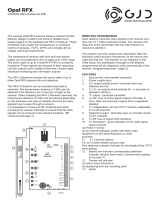
Installation
1. Open the housing by pressing the side of the detector
base and removing the cover.
2. Attach the base to the desired position on the wall or
ceiling.
3. Insert the enclosed 3 V CR2 lithium battery correctly.
4. To deactivate the internal LED, connect the jumper on
contact LK3 on one pin only.
5. If the green cable is connected to the screw clamp block
contact marked “Alarm”, jumper contact LK1 must be
open.
6. When connecting the detector, ensure that the tamper
contact is correctly positioned.

18
1
2
3
4
5
6
Jumper connection LK3 – learn LED on/off
Jumper connection LK1 – swap inputs
Hole
Battery
Hole
Tamper switch

20
Training
1. Set the wireless alarm system / wireless receiver to
learning mode. See the receiver instructions for more
details.
2. Wireless variations:
Activate the tamper contact of the wireless glass
breakage detector to send a tamper message to the
wireless alarm system.
IR variation:
Point the LED of the glass breakage detector at the IR
receiver of the wireless extension (RFX). Trigger the
tamper contact of the glass breakage detector.
3. Make sure that the glass breakage detector is
recognised by your wireless alarm system / wireless
receiver, then close the housing.
Walk test
1. Switch the alarm system to walk test mode (see the
relevant installation instructions).
2. Test whether the detector and the LED are working by
clapping loudly. The LED flashes twice.
3. Use a glass breakage simulator to check the response
of the detector. The LED lights up for a few seconds.
The detector now sends an alarm signal to the alarm
centre.

21
4. Open the housing. The detector now sends a tamper
signal to the alarm centre.
Idle time
The default idle time of the detector is set to one minute.
This function works as follows:
1. The detector recognises a noise and sends a signal to
the centre. The idle time now begins. The LED flashes
once per second in this time.
2. When the idle time has expired, the detector can then
detect the next noise and send a signal to the centre.
This product complies with the requirements of the EU
directive: 1995/5/EC “Directive on radio and
telecommunications terminal equipment and the mutual
recognition of their conformity”.
The declaration of conformity can be ordered from:
ABUS Security-Center GmbH & Co. KG
86444 Affing
GERMANY
www.abus-sc.eu
/