Page is loading ...

MANUAL
IMS-GNM181 Setup Guide
Hot-Plug Module
25th February 2020
Meinberg Funkuhren GmbH & Co. KG


Table of Contents
1 Imprint 1
2 Introduction 2
3 Safety Instructions for hot pluggable Modules 3
3.1 Additional Safety Hints . . . . . . . . . . . . . . . . . . . . . . . . . . . . . . . . . . . . . . . . . . . 4
3.2 Cabling . . . . . . . . . . . . . . . . . . . . . . . . . . . . . . . . . . . . . . . . . . . . . . . . . . . . . 4
3.3 Prevention of ESD Damage . . . . . . . . . . . . . . . . . . . . . . . . . . . . . . . . . . . . . . . . . 4
4 Front Connectors GNM181 GNSS Multi Band Receiver 6
4.1 Status LEDs GNM 181 . . . . . . . . . . . . . . . . . . . . . . . . . . . . . . . . . . . . . . . . . . . 7
4.2 Multiref COM 0 . . . . . . . . . . . . . . . . . . . . . . . . . . . . . . . . . . . . . . . . . . . . . . . . 7
4.3 GNM181 Multi Band Receiver . . . . . . . . . . . . . . . . . . . . . . . . . . . . . . . . . . . . . . . 8
4.4 XHE-SPI . . . . . . . . . . . . . . . . . . . . . . . . . . . . . . . . . . . . . . . . . . . . . . . . . . . 9
5 Before you start 10
5.1 Scope of delivery . . . . . . . . . . . . . . . . . . . . . . . . . . . . . . . . . . . . . . . . . . . . . . . 10
5.2 Disposal of Packaging Materials . . . . . . . . . . . . . . . . . . . . . . . . . . . . . . . . . . . . . . 11
6 System Installation 12
6.1 Important Hints for hot-pluggable IMS Modules . . . . . . . . . . . . . . . . . . . . . . . . . . . . . 12
6.2 Replacement or Installation of a Hot-pluggable IMS Module . . . . . . . . . . . . . . . . . . . . . 13
6.3 Installation GNSS Multiband Antenna . . . . . . . . . . . . . . . . . . . . . . . . . . . . . . . . . . 14
6.4 Connecting the System . . . . . . . . . . . . . . . . . . . . . . . . . . . . . . . . . . . . . . . . . . . 18
7 Configuration of GNSS Receiver 19
7.1 Clock . . . . . . . . . . . . . . . . . . . . . . . . . . . . . . . . . . . . . . . . . . . . . . . . . . . . . . 19
7.1.1 Serial Interfaces . . . . . . . . . . . . . . . . . . . . . . . . . . . . . . . . . . . . . . . . . . . 20
7.1.2 Time Zone . . . . . . . . . . . . . . . . . . . . . . . . . . . . . . . . . . . . . . . . . . . . . . 21
7.1.3 Enabling the Outputs . . . . . . . . . . . . . . . . . . . . . . . . . . . . . . . . . . . . . . . . 21
7.1.4 Miscellaneous . . . . . . . . . . . . . . . . . . . . . . . . . . . . . . . . . . . . . . . . . . . . 22
7.1.5 Initialize Receiver . . . . . . . . . . . . . . . . . . . . . . . . . . . . . . . . . . . . . . . . . . 24
7.1.6 Receiver Information . . . . . . . . . . . . . . . . . . . . . . . . . . . . . . . . . . . . . . . . . 25
7.1.7 Switch Card . . . . . . . . . . . . . . . . . . . . . . . . . . . . . . . . . . . . . . . . . . . . . 26
7.1.8 Receiver Information Switch Card . . . . . . . . . . . . . . . . . . . . . . . . . . . . . . . . . 26
8 Technical Specifications GNSS Multiband Antenna 27
8.1 MBG S-PRO - Technical Specifications . . . . . . . . . . . . . . . . . . . . . . . . . . . . . . . . . 29
8.1.1 MBG S-PRO - Physical Dimensions . . . . . . . . . . . . . . . . . . . . . . . . . . . . . . . 31
8.1.2 Installation and Grounding . . . . . . . . . . . . . . . . . . . . . . . . . . . . . . . . . . . . . 31
9 RoHS and WEEE 32
Date: 25th February 2020 IMS-GNM181 Setup Guide

1 Imprint
1 Imprint
Meinberg Funkuhren GmbH & Co. KG
Lange Wand 9, 31812 Bad Pyrmont / Germany
Phone: + 49 (0) 52 81 / 93 09 - 0
Fax: + 49 (0) 52 81 / 93 09 - 230
Internet: https://www.meinbergglobal.com
Mail: [email protected]
Date: 2020-02-25
IMS-GNM181 Setup Guide Date: 25th February 2020 1

2 Introduction
This Setup Guide is a systematically structured guideline which supports you during the set-up of your Mein-
berg product. The individual chapters describe the correct positioning and installation of the antenna as well
as the installation of the coaxial cable. Furthermore, it describes the parameters that have to be configured in
the web interface for a quick start of your product.
The LTOS7 manual provides a complete description of all configurations and status monitoring options of
your Meinberg product.
Download link: https://www.meinbergglobal.com/download/docs/manuals/english/ltos_7-00.pdf
2 Date: 25th February 2020 IMS-GNM181 Setup Guide

3 Safety Instructions for hot pluggable Modules
3 Safety Instructions for hot pluggable Modules
Check before every maintenance work on the system:
• If a data backup is required?
• Is a backup required, verify the data recovery which is done by this backup.
• Make sure to avoid any static discharge while working - use a grounding cable and/or antistatic gloves
during installation and removal of hot pluggable components.
• If you are replacing a hot pluggable power supply, unplug the power cable prior to removing the module
from the case.
• Never open a power supply. In power supplies dangerous voltages can still remain even after disconnection
from the power supply. Always send power supplies back to the manufacturer for maintenance.
Exchange of hot-swap components
• Ensure that components which will be replaced during operation, always be treated with the utmost care.
Avoid contact with live components.
• Electrostatic discharge can damage electronic components. For this reason, ensure protection against
electrostatic discharges by wearing anti-static shoes while working with the system.
• Take care when removing and installing the hot-plug modules. Always work with the utmost caution.
Touch the modules only at the edges.
• Place the module out of the box or after removal from the system with the component side to the top on
a grounded and static-free surface.
• Storage of an IMS module must be done in a dry place.
• Installation or removal from hot-swap components only by authorized personnel!
IMS-GNM181 Setup Guide Date: 25th February 2020 3

3.1 Additional Safety Hints
This manual contains important information for the installation and operation of thi s device as well as for your
safety. Make sure to read carefully before installing and commissioning the device.
Certain operating conditions may require the observance of additional safety regulations not covered by this
manual. Nonobservance of this manual will lead to a significant abatement of the security provided by this
device. Security of the facility where this product is integrated lies in the responsibility of the installer.
The device must be used only for purpose named in this manual, any other use especially opteration above the
limits specified in this document is considered as improper use.
Keep all documents provided with the device for later reference.
This manual is exclusively for qualified electricians or by a qualified electrician trained personnel who are
familiar with the applicable national standards and specifications, in particular for the construction of high
voltage devices.
3.2 Cabling
WARNING!
DANGER TO LIFE BY ELECTRICAL SHOCK! NO LIVE WORKING!
Wiring or any other work done the connectors particularly when connectors are opened may never be carried out
when the installation is energized. All connectors must be covered to prevent from accidental contact to life parts.
ALWAYS ENSURE A PROPER INSTALLATION!
3.3 Prevention of ESD Damage
ATTENTION!
The designation ESD (Electrostatic Sensitive Devices) refers to measures which are used
to protect electrostatically endangered components from electrostatic discharge and thus
to prevent destruction. Systems and assemblies with electrostatically endangered components
usually have the following characteristics:
Indicator for assemblies with electrostatic endangered components
The following measures protect electrostatically endangered components from destruction:
Prepare removal and installation of assemblies
Unload yourself (for example, by touching a grounded object) before touching assemblies.
Ensure that you wear a grounding strap on the wrist when working with such assemblies, which
you attach to an unpainted, non-conductive metal part of the system.
4 Date: 25th February 2020 IMS-GNM181 Setup Guide

3 Safety Instructions for hot pluggable Modules
Use only tools and devices that are free from static electricity.
Transporting Assemblies
Assemblies may only be touched at the edge. Do not touch any pins or conductors on assemblies.
Installing and Removing Assemblies
Do not touch persons who are not grounded while removing or installing components. This could
result in a loss of grounding protection from your electrostatic discharge.
Storing Assemblies
Always keep assemblies in ESD protective covers. These protective covers must be undamaged.
ESD protective covers, which are extremely wrinkled or even have holes, no longer protect against
electrostatic discharge.
ESD protective covers must not be low-resistance and metallically conductive if a lithium battery
is installed on the assembly.
IMS-GNM181 Setup Guide Date: 25th February 2020 5

4 Front Connectors GNM181 GNSS Multi Band
Receiver
GNM 181 / 4TE
Init
Nav
Ant
Fail
Antenna
GNSS
L1 + L2 | 5 V
GNM 181
C O M
1
2
3
GNM 181 / 8TE
GNM 181
Init
Nav
Ant
Fail
XHE-SPI
1
3
5
C O M
1
2
3
4
Antenna
GNSS
L1 + L2 | 5 V
6 Date: 25th February 2020 IMS-GNM181 Setup Guide

4 Front Connectors GNM181 GNSS Multi Band Receiver
4.1 Status LEDs GNM 181
LED Indicators
Init blue: while the receiver passes through
the initialization phase
green: the oscillator has warmed up
Nav. green: positioning successfully
Ant red: antenna faulty or not connected
yellow: the clock is synchronized by an external
Signal - MRS mode (PPS, IRIG ...)
Fail red: time has not synchronized
Fail
Ant.
Nav.
Init
4.2 Multiref COM 0
The COM 0 interface of the GNM 181 is used for serial communication (RS-232 signal level). It can also be
used as an optional "Multiref" interface for the reference signal PPS + String.
Assignment:
Pin 2: RxD (receive)
Pin 3: TxD (transmit)
Pin 5: GND (ground)
Reference signal via 9-pin DSUB connector
(PPS + String Mode)
Pin 1: PPS
Pin 2: String *
* The following timestrings (time telegrams)
can be used:
NMEA RMC
NMEA ZDA
Meinberg Standard
Uni Erlangen
COM
IMS-GNM181 Setup Guide Date: 25th February 2020 7

4.3 GNM181 Multi Band Receiver
Receiver Type 184-channel
GPS, GLONASS, Galileo, Beidou
Frequency Band: GPS:
L1C/A (1575.42 MHz)
L2C (1227.60 MHz)
GLONASS:
L1OF (1602 MHz + k*562.5 kHz
L2OF (1246 MHz + k*437.5 kHz
k = –7,..., 5, 6
Galileo:
E1-B/C (1575.42 MHz)
E5b (1207.140 MHz)
Beidou:
B1I (1561.098 MHz) B2I (1207.140 MHz)
Accuracy of Pulses: Dependant on oscillator option:
< +-100ns (TCXO, OCXO LQ)
< +-50ns (OCXO-SQ, -MQ, -HQ, -DHQ)
Synchronization Time: <1 minute in normal operation mode,approx.
1 minutes after a cold start (12 minutes in GPS only mode)
Signal Gain 40 dB
Antenna Gain: ≥ 3.5 dBic / ≥ 3 dBic
Power Supply 5 V DC (via antenna cable)
Nominal Impedance: 50 Ohm
Connection Type: SMA female / Antenna
Cable: shielded coaxial line (Belden H155)
Cable lenght: deductible up to max. 70m
Backup Battery Type: CR2032 – button cell lithium battery.
The hardware clock and the RAM are battery buffered. When the main power supply fails,
the hardware clock runs free on quartz basis and the almanac data is stored in the RAM.
Life time of lithium battery: min. 10 years
Antenna
GNSS
L1 + L2 | 5 V
WARNING!
Working on the antenna system during thunderstorms
Danger to life due to electrical shock!
- Do not carry out any work on the antenna system or the antenna cable
if there is a risk of a lightning strike.
- Do not carry out any work on the antenna system if the safety distance
to free lines and sequential circuits is exceeded.
8 Date: 25th February 2020 IMS-GNM181 Setup Guide

4 Front Connectors GNM181 GNSS Multi Band Receiver
4.4 XHE-SPI
Pin Assignment of the optional XHE-SPI Connectors:
A1: PPS In
A2: PPS Out
Pin 1: SCL_Out (SPI Clock)
Pin 2: CS (Chip Select)
Pin 3: MOSI (Master Out, Slave In)
Pin 4: MISO (Master In, Slave Out)
Pin 5: GND
Attention: Use this plug only to connect a Mein-
berg IMS-XHE
Rb
Rubidium expansion chassis.
IMS-GNM181 Setup Guide Date: 25th February 2020 9

5 Before you start
5.1 Scope of delivery
3
5
2
4
6
4x 4x
4x
1
Included in delivery of a Meinberg GNM181 receiver module:
1. GNSS Multi Band antenna
2. Surge voltage protector (optional)
3. 20 m Antenna cable (Belden H155)
4. Coax cable for surge voltage protector (optional)
5. Retaining tube and clips for Meinberg GNSS-Multi Band antenna
6. Mounting kit for Meinberg GNSS-Multi Band antenna
Carefully unpack the system and all accessories and put them aside. Check the scope of delivery with the pack-
ing list to ensure that no parts are missing. If any of the li sted contents are mi ssing, please contact Meinberg
Funkuhren.
Check the system for shipping damage. If the system is damaged or cannot be put into operation, contact
Meinberg Funkuhren immediately. Only the recipient (the person or company receiving the system) can assert
a claim against Freight Forwarder for shipping damage.
Meinberg recommends that you keep the original packaging materials for possible future transport.
10 Date: 25th February 2020 IMS-GNM181 Setup Guide

5 Before you start
5.2 Disposal of Packaging Materials
The packaging materials we use are fully recyclable:
Material Use for Disposal
————————————————————————————————————————
Cardboard shipping packaging, Paper recycling
accessories packaging
Foil shipping packaging, Household waste or recycling depot
accessories packaging
————————————————————————————————————————
IMS-GNM181 Setup Guide Date: 25th February 2020 11

6 System Installation
6.1 Important Hints for hot-pluggable IMS Modules
The following points should be strictly observed when replacing IMS modules during operation. Not all IMS
modules are fully hot-pluggable. Of course, it is not possible to replace a power supply unit of a non-redundant
system without first having installed a second power source in operational mode.
The following applies to the individual IMS slots:
PWR: "hot swappable" If you operate your system with only one
power supply, a second power supply must
be installed before removing/replacing it
to keep your system functioning.
I/O, ESI and MRI Slots: "hot swappable".
CLK1, CLK2: "hot swappable" Afer the exchange or the installation of a
clock module a rescan of the reference clocks
(Rescan Refclocks) must be executed in the web
interface menu "System".
CPU not "hot swappable" The central management unit must be disconnected
from mains before replacement.
RSC/SPT not "hot swappable" The RSC switching card must be disconnected
from the mains before the replacement.
12 Date: 25th February 2020 IMS-GNM181 Setup Guide

6 System Installation
6.2 Replacement or Installation of a Hot-pluggable IMS Module
If the system is supplied with an antenna and antenna cable, it is advisable to first mount the antenna in a
suitable location (see chapter Antenna Mounting) and lay the antenna cable.
Please use a Torx screwdriver (T8 x 60) for removal and installation of the module.
1. Follow the safety instructions at the beginning
of this manual!
2. Remove the two marked Torx screws from the
module holder plate or the cover plate of
the empty slot.
3. Note when removing!
Pull the module carefully out of the guide
rail. Note that the module is firmly anchored
in the connector block of the housing. You need
a certain amount of force to release the module
from this link. Once the connection to the
connector block of the system’s backplane is
loosened, the module can be easily pulled out.
4. Note during installation!
Please ensure that the module is correctly inserted into the
two guide rails of the system housing as otherwise damage to the module and the housing could be caused.
Make sure that the module is securely locked into the connector block before you fasten the two screws.
5. Now you can put the installed module into operation.
Attachment points of an 1U IMS system
IMS-GNM181 Setup Guide Date: 25th February 2020 13

6.3 Installation GNSS Multiband Antenna
WARNING!
Antenna mounting without effective anti-fall protection
Danger to life due to fall!
- Pay attention to effective working safety when installing antennas!
- Never work without an effective anti-fall equipment!
WARNING!
Working on the antenna system during thunderstorms
Danger to life due to electrical shock!
- Do not carry out any work on the antenna system or the antenna cable
if there is a risk of a lightning strike.
- Do not carry out any work on the antenna system if the safety distance
to free lines and sequential circuits is exceeded.
1. Selection of the Antenna location
To receive enough satellites, select a location that allows an unobstructed view of the sky, otherwise there
may be problems with the synchronization of the system. There should be no obstacle in the line of sight
between the antenna and the satellites. In addition, the antenna must not be installed under high-voltage lines
or other electrical light or electric circuits.
Installation conditions for optimal operation:
• Free view from 8
◦
above the horizon or
• free view towards equator (if free view of 8
◦
not possible) or
• clear view between 55th southern and 55th nor thern latitude (satellite orbits).
If this view is also restricted, there may be complications in case four
satellites have to be found for a calculation of a new position.
14 Date: 25th February 2020 IMS-GNM181 Setup Guide

6 System Installation
Antenna Mounting
1.
Mount the antenna at a minimum distance of 50 cm
from other antennas to an vertical pole up to 60 mm
outer diameter or on a wall with the mounting kit in-
cluded in the scope of delivery.
Then connect the antenna cable (Belden H155) to
the N-Norm connector of the antenna. Lead the other
end of the cable through the wall into the building.
GNSS Antenna
N-Norm (female)
N-Norm (male)
Free view to the sky!
Make sure that the maximum cable length is kept when installing the antenna
cable between the antenna and receiver. This depends on the type of cable
used (H155, RG58) and its damping factor.
IMS-GNM181 Setup Guide Date: 25th February 2020 15

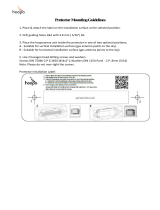
2.
The optional overvoltage protection MBG S-PRO can
be mounted now. This is also suitable for outdoor in-
stallation (protection class: IP55). However, Meinberg
recommends an installation in closed rooms, just after
the antenna cable has entered the wall, in order to
reduce the risk of overvoltage damage, e.g. due to
lightning strikes.
Connect the other side of the antenna cable to the
surge protection socket.
N-Norm (male)
N-Norm (female)
Outside wall of the building
Outdoor installation
Inside a waterproof housing.
Indoor installation
(recommended)
Just after the antenna cable enters
N-Norm (female)
N-Norm (male)
MBG S-PRO
MBG S-PRO
the wall.
3.
The next step is to connect the supplied coaxial cable
between the surge protector and receiver.
N-Norm (female)
N-Norm (male)
SMA (female)
BNC (female)
N-Norm (male)
N-Norm (female)
BNC (male)
Receiver
Antenna splitter
SMA (male)
GNSS
MBG S-PRO
Optional
16 Date: 25th February 2020 IMS-GNM181 Setup Guide

6 System Installation
Antenna splitter option
Several receivers can be connected to one antenna via the antenna splitter. Make sure, that the total length of
a route going from the antenna via the splitter to the receiver, does not exceed the maximum cable length. The
splitter can be installed at any position between antenna or, if used, the surge protector and receiver.
Receiver
Antenna splitter
Antenna
GNSS
GNSS
In
Out 3
Out 1
Out 2
Out 4
Route AB = 65 m (H155) - Total length „OK“
Route AC = 110 m (H155) - max. total length exceeded
A
B
C
Compensation the signal propagation time of the antenna cable
The receiving satellite signal i s delayed by the used coaxial cable. The connected receiver must compen-
sate the signal propagation time of the antenna cable, therefore you need to enter the length of the antenna
cable in meters or the compensation time in nanoseconds into the settings of your receiver.
Antenna Cable Length (m):
Cable Delay Usage
RG58U 5 ns/m for GPS180 and GNS-UC
H155 4 ns/m for GNS180 and GNM
By entering the cable length (from antenna to receiver), the system calculates the delay time and compen-
sates it automatically.The default value of 20 m is preconfigured at delivery.
For other coaxial cable types please use the option "by delay". The delay must be calculated by yourself
by using the information in the data sheet of the respective coaxial cable.
IMS-GNM181 Setup Guide Date: 25th February 2020 17
/