Page is loading ...

Binks SV50 HVLP
GRAVITY FEED SPRAY GUN
& TOUCHUP GUN
Replaces
Part Sheet
77-2891
Part
Sheet
77-2891R
ATTENTION!
READ BEFORE ATTACHING THE AIR HOSE
HVLP AIR SUPPLY REQUIREMENTS
FULL SIZE GUN: 30 PSI inlet pressure provides 10 PSI at the air cap. Consumes 12 CFM.
TOUCHUP GUN: 30 PSI inlet pressure provides 10 PSI at the air cap. Consumes 8 CFM.
NOTE: USE 5/16" OR LARGER I.D. AIR HOSES
SPECIFICATIONS
Max. Air Pressure: 100psi
For HVLP Compliance: 30 psi inlet pressure delivers
10 psi air cap pressure
Gun Body: Cast Aluminum
Fluid Path: Aluminum
Fluid Nozzle: Stainless Steel
Fluid Needle: Stainless Steel
Air Inlet Size: 1/4" NPS(M)
OPERATION AND MAINTENANCE INSTRUCTIONS
Your new SV50 Gravity Feed Spray Gun and Gravity Feed
Touchup Gun are exceptionally rugged in construction and
built to stand up under hard, continuous use. However, like
any other fine precision instruments, their most efficient
operation depends on a knowledge of their construction,
operation, and maintenance. Properly handled and cared
for, they will produce beautiful, uniform finishing results
long after other spray guns have worn out.
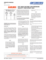
SET-UP FOR SPRAYING (Figure 1)
CONNECTING GUN TO AIR HOSE
Air should be supplied by a suitable length of 5/16"
diameter air hose fitted with a 1/4 NPS(f) connection to
the base of the gun handle. For hose lengths over 50',
use 3/8" hose.
CONNECTING GRAVITY FEED CUP TO GUN
Screw the cup into the spray gun fluid inlet. Fill the
cup with filtered paint.
If desired, attach air adjusting valve with gauge and/or
quick disconnect to air inlet, then attach hose. Spray test
and adjust air pressure, fan size, and fluid flow as
required. Recommended spray distance is 6-8 inches.
Figure 1
WARNING
Servicing the gun while pressurized could result in compo-
nents or material exiting the gun at high velocity, possibly
resulting in personal injury or damage to the spray gun.
Before removing any components from the spray gun, shut
off air pressure and drain material from the paint cup.
!
Gravity
Feed
Cup
Fluid
Inlet
Gravity
Feed
Srpay Gun
Fan
Size
Control
Material
Flow
Control
Air Hose
WARNING
A failure resulting in injury or
damage may be caused by
pressure beyond top of scale,
excessive vibration or pressure
pulsation, excessive instrument
temperature, corrosion of the
pressure containing parts or
other misuse of the air adjusting
valve with gauge.
!

2
Warning
!
In this part sheet, the words WARNING, CAUTION and NOTE are used to emphasize important safety information as follows:
CAUTION
Hazards or unsafe practices which could
result in minor personal injury, product
or property damage.
!
WARNING
Hazards or unsafe practices which could
result in severe personal injury, death or
substantial property damage.
!
NOTE
Important installation, operation or
maintenance information.
Read the following warnings before using this equipment.
READ THE MANUAL
Before operating finishing equipment, read and
understand all safety, operation and maintenance
information provided in the operation manual.
AUTOMATIC EQUIPMENT
Automatic equipment may start suddenly without
warning.
INSPECT THE EQUIPMENT DAILY
Inspect the equipment for worn or broken parts
on a daily basis. Do not operate the equipment
if you are uncertain about its condition.
NEVER MODIFY THE EQUIPMENT
Do not modify the equipment unless the
manufacturer provides written approval.
KNOW WHERE AND HOW TO SHUT OFF THE
EQUIPMENT IN CASE OF AN EMERGENCY
PRESSURE RELIEF PROCEDURE
Always follow the pressure relief procedure in the
equipment instruction manual.
NOISE HAZARD
You may be injured by loud noise. Hearing
protection may be required when using this
equipment.
STATIC CHARGE
Fluid may develop a static charge that must be
dissipated through proper grounding of the
equipment, objects to be sprayed and all other
electrically conductive objects in the dispensing
area. Improper grounding or sparks can cause a
hazardous condition and result in fire, explosion
or electric shock and other serious injury.
FIRE AND EXPLOSION HAZARD
Never use 1,1,1-trichloroethane, methylene
chloride, other halogenated hydrocarbon solvents
or fluids containing such solvents in equipment
with aluminum wetted parts. Such use could
result in a serious chemical reaction, with the
possibility of explosion. Consult your fluid
suppliers to ensure that the fluids being used are
compatible with aluminum parts.
WEAR SAFETY GLASSES
Failure to wear safety glasses with side shields
could result in serious eye injury or blindness.
DE-ENERGIZE, DISCONNECT AND LOCK OUT ALL
POWER SOURCES DURING MAINTENANCE
Failure to De-energize, disconnect and lock out
all power supplies before performing equipment
maintenance could cause serious injury or death.
OPERATOR TRAINING
All personnel must be trained before operating
finishing equipment.
EQUIPMENT MISUSE HAZARD
Equipment misuse can cause the equip ment to
rupture, malfunction, or start unexpectedly and
result in serious injury.
KEEP EQUIPMENT GUARDS IN PLACE
Do not operate the equipment if the safety
devices have been removed.
PROJECTILE HAZARD
You may be injured by venting liquids or gases
that are released under pressure, or flying debris.
PINCH POINT HAZARD
Moving parts can crush and cut. Pinch points are
basically any areas where there are moving parts.
CA PROP
65
PROP 65 WARNING
WARNING: This product contains chemicals known
to the State of California to cause cancer and
birth defects or other reproductive harm.
FOR FURTHER SAFETY INFORMATION REGARDING BINKS AND DEVILBISS EQUIPMENT,
SEE THE GENERAL EQUIPMENT SAFETY BOOKLET (77-5300).
IT IS THE RESPONSIBILITY OF THE EMPLOYER TO PROVIDE THIS INFORMATION TO THE OPERATOR OF THE EQUIPMENT.

3
To reduce overspray and obtain maximum efficiency,
always spray with the lowest possible fluid/air pressure
that produces an acceptable spray pattern.
Excessive atomizing air pressure can increase overspray,
reduce transfer efficiency and with some materials, result
in poor finish quality from dry spray.
Generally use up to 20 psi air at gun inlet. Unusually
heavy, difficult to atomize materials may require up to
30 psi at gun inlet. See Specifications on page 1.
GENERAL SPRAY INSTRUCTIONS
The first requirement for a good resultant finish is the
proper handling of the gun. The gun should be held
perpendicular to the surface being covered and moved
parallel with it. The stroke should be started before the
trigger is pulled and the trigger should be released before
the stroke is ended. This gives accurate control of the
gun and material.
The distance between gun and surface should be 6 to
8 inches depending on material and atomizing pressure.
The material deposited should always be even and wet.
Lap each stroke over the preceding stroke to obtain a
uniform finish.
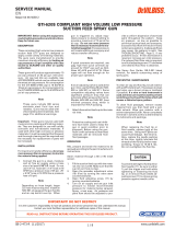
SPRAY TECHNIQUE
Coating should be even
and wet when spraying
Coating will
be light at
this point
Coating will
be heavy
at this point
Start
stroke
Pull
trigger
Release
trigger
End of
stroke
RIGHT WRONG
TRAVEL OF GUN
6 to 8 inches
AIR CAP
PACKING
NUT
FLUID NEEDLE
FAN CONTROL
FLUID NEEDLE CONTROL
AIR
ADJUSTING
VALVE
PACKING ADJUSTMENT INSTRUCTIONS
Before using this spray gun, the packing nut should be
adjusted as follows:
1. Tighten packing nut until fluid needle starts to bind
in the packing.
2. Loosen packing nut just enough so the fluid needle
moves freely.
The packing nut is intentionally left loose so the PTFE
packing does not take a “set” before the spray gun is used.
This allows full utilization of the packing.
PREVENTIVE MAINTENANCE
A
C
B
D
SPRAY GUN LUBRICATION
Apply a drop of SSL-10 spray gun lube at trigger bearing
stud and the stem of the air valve. The shank of the fluid
needle where it enters the packing nut should also be
oiled. The fluid needle packing should be kept soft and
pliable by periodic lubrication. Make sure the baffle and
retaining ring threads are clean and free of foreign matter.
Before assembling retaining ring to baffle, clean the
threads thoroughly, then add two drops of SSL-10 spray
gun lube to threads. The fluid needle spring and air valve
spring should be coated with a very light grease, making
sure that any excess grease will not clog the air passages.
For best results, lubricate the points indicated, daily.
A. Trigger Points
B. Packing
C. Adjusting Valves
D. Baffle/Air Cap Threads

4
NOTE
To reduce overspray and obtain maximum efficiency always spray with the lowest possible atomizing air pressure.
CAUTION
Never use metal instruments to clean the air or fluid nozzles.
These parts are carefully machined and any damage to them will cause faulty spray.
!
AIR NOZZLE, FLUID NOZZLE, FLUID NEEDLE
1. All nozzles and needles are precision made. They
should be handled with care.
2. Do not make any alterations in the gun. To do so
could cause finishing difficulties.
3. To clean nozzles, soak them in solvent to dissolve
any dried material, then blow them clean with air.
4. Do not probe any of the holes in the nozzles with
metal instruments. If probing is necessary, use only a
tool that is softer than brass.
OPERATING THE SV50 GRAVITY FEED SPRAY GUN
CONTROLLING THE MATERIAL FLOW
Correct fluid nozzle size should be selected for proper
material flow rate. The material valve control knob may
be used to restrict the material needle valve opening and
reduce the material flow as necessary.
CONTROLLING THE FAN SPRAY
The fan spray is controlled by means of the spray pattern
valve control assembly. Turning this control clockwise
until it is closed will give a round spray. Turning it counter-
clockwise will widen the spray into a fan shape. The fan
spray can be turned anywhere through 360° by positioning
the air cap relative to the gun. To affect this, loosen retainer
ring, position nozzle, then tighten retainer ring.
TROUBLE SHOOTING
FAULTY SPRAY
A faulty spray is often caused by improper cleaning result-
ing in dried materials around the material nozzle tip or in
the air nozzle. Soak these parts in thinners to soften the
dried material and remove with a brush or cloth. If either
the air cap or fluid nozzle are damaged, these parts must be
replaced before perfect spray can be obtained.
INTERMITTENT SPRAY
Fluttering spray is caused by one of the following:
1. Insufficient material in cup. Refill the cup.
2. Loose fluid nozzle. Tighten snugly.
3. Cup connection loose or dirt in connection.
Correct as necessary.
4. Air vent in gravity cup blocked. Clear obstruction.
SPRAY GUN CLEANING INSTRUCTIONS
In certain states, spraying solvents which contain Volatile
Organic Compounds (VOC) into the atmosphere when
cleaning a spray gun is now prohibited.
In order to comply with these new air quality laws,
Binks recommends one of the following two methods
to clean your spray finishing equipment.
1. Spray solvent through the gun into a closed system. An
enclosed unit or spray gun cleaning station condenses
solvent vapors back into liquid form which
prevents escape of VOCs into the atmosphere.
2. Place spray gun in a washer type cleaner. This system
must totally enclose the spray gun, cups, nozzles and
other parts during washing, rinsing and draining
cycles. This type of unit must be able to flush solvent
through the gun without releasing any VOC vapors
into the atmosphere.
CLEANING GUN AND GRAVITY FEED CUP
Remove the cup cover and drain unused material from
cup. Carefully rinse cup with solvent. Place clean solvent
into the cup and spray this through the gun until it is
clean. Remove and clean the cup if necessary. Blow air
through the gun to dry it. (Refer to Service Bulletin SBBI-
4-043 for cleaning instructions when using cup liners.)
CAUTION
Never use metal instruments to clean the air or material
nozzles. These parts are carefully machined and any damage
to them will cause faulty spray.
!

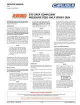
BINKS SV50 HVLP GRAVITY FEED SPRAY GUN & TOUCHUP GUN
5
30
31
29
28
27
6
7-1
7-2 7
8
9
10
11
13
12
14 15 16+17 18 19 20
26
7-2
7-1
25
01 32 02 05
21 22 23 22 24 21
03
04
REF. DESCRIPTION
01 AIR CAP w/Ring
02 FLUID NOZZLE
03 NUT
04 GASKET
05 GUN BODY
06 HOOK
07 FAN CONTROL
7-1 C-CLIP (2 pcs.)
7-2 O-RING (2 pcs.)
08 GASKET
09 O-RING
10 HOUSING
11 PAINT NEEDLE
12 SPRING
13 KNOB, FLUID CONTROL
14 GASKET
15 SCREW
REF. DESCRIPTION
16+17 VALVE STEM COMPLETE
18 SPRING
19 O-RING
20 AIR VALVE NUT
21 E-RING (2 pcs.)
22 WASHER (2 pcs.)
23 TRIGGER
24 TRIGGER STUD
25 AIR CONTROL
26 AIR INLET FITTING
27 FILTER
28 GASKET for Fitting (2 pcs.)
29 600cc ALUM. CUP
250cc ALUM. CUP
30 LID
31 GASKET for Lid
32 GASKET for Air Cap
PARTS LIST

6
NOTES

NOTES
7

5/12 ©2012 Binks All rights reserved. Printed in U.S.A.
U.S.A./ Canada Customer Service
195 Internationale Blvd.
Glendale Heights, IL 60139
630-237-5000
Toll Free Customer Service
and Technical Support
800-992-4657
Toll Free Fax
888-246-5732
Binks Sales and Service: www.binks.com
WARRANTY
This product is covered by Binks’ 1 Year Limited Warranty.
77-2891R Revisions: (P2) Added Prop 65 warning;
(P3) PTFE reference update; (P8) Updated contact
information.
/