Page is loading ...

DXCM024-0348
Manual Hose Reel With 50' Rubber Hose
Manual De Manguera De Aire Con Manguera De Aire - 15,2 m
Dévidoir Manual D'air Avec Tuyau D'air - 15,2 m
INSTRUCTION MANUAL
GUIDE D'UTILISATION
MANUAL DE INSTRUCCIONES
INSTRUCTIVO DE OPERACIÓN, CENTROS DE SERVICIO Y
PÓLIZA DE GARANTÍA. ADVERNTENCIA: LÉASE ESTE
INSTRUCTIVO ANTES DE USAR EL PRODUCTO.
If you have questions or comments, contact us.
Pour toute question ou tout commentaire, nous contacter.
Si tiene dudas o comentarios, contáctenos.
1-800-4-DEWALT • www.dewalt.com
MAT Industries, LLC, Long Grove, IL 60047
(OCT17) Part No. 200-3081-C DXCM024-0348 Copyright © 2017 DEWALT

2
English
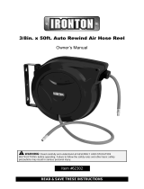
DXCM024-0348 Air Hose Reel
A. Handle
B. Hose Reel
C. 1/4" Air Line Inlet
D. Mounting Bracket
E. Quick Release Pin
F. 1/4" Air Line Outlet
G. 3/8" x 50' Air Hose
H. Manual Brake Pin Lock
I. 3/8" x 3' Lead-in Hose (not shown)
Specications
MODEL DXCM024-0348
NET WEIGHT 28 lbs. (12,7 kg)
AIR INLET 1/4" NPT (6,3 mm)
(female/hembra/femelle)
AIR HOSE TYPE Rubber
AIR HOSE SIZE 3/8" (9,5 mm)
HOSE MAXIMUM OPERATION
PRESSURE
300 PSI (2,068 kPa)
AIR HOSE LENGTH 50' (15,2 m)
FIG. 1
BACKSIDE

3
English
Denitions: Safety Guidelines
The definitions below describe the level of severity
for each signal word. Please read the manual and pay atten-
tion to these symbols.
DANGER: Indicates an imminently hazardous situation
which, if not avoided, will result in death or serious injury.
WARNING: Indicates a potentially hazardous situation
which, if not avoided, could result in death or serious injury.
CAUTION: Indicates a potentially hazardous situation
which, if not avoided, may result in minor or moderate
injury.
CAUTION: Used without the safety alert symbol
indicates a potentially hazardous situation which,
if not avoided, may result in property damage.
IF YOU HAVE ANY QUESTIONS OR COMMENTS ABOUT
THIS OR ANY D
e
WALT TOOL, CALL US TOLL FREE AT:
1-800-4-DEWALT (1-800-433-9258)
Important Safety Instructions
WARNING: Some dust created by power sanding, sawing,
grinding, drilling, and other construction activities contains
chemicals known to the State of California to cause cancer, birth
defects or other reproductive harm. Some example of these
chemicals are:
• Lead from lead-based paints
• Crystalline silica from bricks and cement and other masonry
products
• Arsenic and chromium from chemically-treated lumber
Your risk from these exposures varies, depending on how often you
do this type of work. To reduce your exposure to these chemicals:
work in a well ventilated area, and work with approved safety
equipment, al ways wear OSHA/MSHA/NIOSH approved, properly
fit ting face mask or res pi ra tor when us ing such tools. When
using air tools, basic safety precautions should always be followed
to reduce the risk of personal injury.
WARNING: This product contains chemicals, known to the
State of California to cause cancer, and birth defects or other
reproductive harm. Wash hands after handling.
SAVE THESE INSTRUCTIONS
WARNING:
Improper operation or maintenance of this product
could result in serious injury and property
damage. Read and understand all warnings and
operating instructions before using this
equipment. When using air tools, basic safety
precautions should always be followed to reduce
the risk of personal injury.
WARNING:
Read and understand this instruction manual and tool
labels before installing, operating or servicing this tool.
Keep these instructions in a safe accessible place.
Operators and others in work area must wear ANSI Z87.1
CAN/CSA Z94.3 approved safety glasses with side shields.
Operators and others in work area must wear ear
protection.

4
English
WARNING:
• Do Not Use oxygen or reactive gases; explosion may occur.
• Do Not Exceed air pressure of 300 PSI.
• Read all manuals included with this product carefully.
Be thoroughly familiar with the controls and the proper use
of the equipment.
• Do not exceed any pressure rating of any component
in the system.
• Disconnect the air tool from air supply before changing tools
or attachments and during non-operation.
• Always use attachments designed for use with air
powered tools.
• Do not use damaged or worn attachments.
• Check air hoses for weak or worn condition before each use.
Make sure all connections are secure.
• Keep all nuts, bolts and screws tight and ensure equipment is
in safe working condition.
DANGER: RISK OF EXPLOSION OR FIRE
WHAT CAN HAPPEN HOW TO PREVENT IT
• Exceeding the maximum
pressure rating of tools
accessories could cause an
explosion resulting
in serious injury.
• Use compressed air regu-
lated to a maximum pressure
at or below the rated pressure
of any attachments.
DANGER: RISK TO BREATHING (ASPHYXIATION)
WHAT CAN HAPPEN HOW TO PREVENT IT
• Abrasive tools, such as
grinders, sanders, and
cut-off tools generate dust
and abrasive materials which
can be harmful to human
lungs and respiratory system.
• Always wear MSHA/NIOSH
approved, properly fitting face
mask or respirator when using
such tools.
CAUTION: RISK FROM NOISE
WHAT CAN HAPPEN HOW TO PREVENT IT
• Long term exposure to noise
produced from the operation
of air tools can lead to
permanent hearing loss.
• Always wear ANSI (S3.19)
hearing protection.

5
English
WARNING: RISK OF INJURY
WHAT CAN HAPPEN HOW TO PREVENT IT
• Air tools can propel loose
objects or other materials
throughout the work area.
• Keep work area clean and free
of clutter. Keep children and
others away from work area
during operation of the tool.
• Keep work area well lit.
• Exceeding the pressure rating
of air hoses can cause them
to explode or fly apart, and
could result in serious injury.
•
Use compressed air regulated
to a maximum pressure at or
below the rated pressure of
any attachments.
•
Never use oxygen, carbon
dioxide or other bottled gases
as a power source for air tools.
•
Protect air lines from damage
or puncture.
•
Check air hoses for weak or
worn condition before each
use. Make sure all connections
are secure.
WARNING: RISK FROM FLYING OBJECTS
WHAT CAN HAPPEN HOW TO PREVENT IT
• Air powered equipment and
power tools are capable of
propelling materials such as
metal chips, saw dust, and
other debris at high speed,
which could result in serious
eye injury.
• Always wear ANSI Z87.1 CAN/
CSA Z94.3 approved safety
glasses with side shields.
• Never leave operating tool
unattended. Disconnect air
hose when tool is not in use.
• Compressed air can be
hazardous. The air stream
can cause injury to soft tissue
areas such as eyes, ears, etc.
Particles or objects propelled
by the stream
can cause injury.
• For additional protection use an
approved face shield in addition
to safety glasses.
SAVE THESE INSTRUCTIONS FOR FUTURE
USE

6
English
FEATURES
HANDLE
The plastic handle (A) has an internal swivel
for smooth rotation. Easily attaches to the
hose reel with the supplied fasteners.
AIR LINE INLET
The air line inlet (C) is 1/4"
NPT and is located on the on
the mounting plate that is
attached to the hose reel.
MOUNTING BRACKET
The mounting bracket (D) is a
powder coated metal plate that
can be easily mounted on a wall
and comes with a quick release
pin (E) for remote use.
AIR LINE OUTLET
The air line outlet (F) is 1/4" NPT and
is located on the end of the air hose
(G) for convienient connection to air
accessories or tools.
AIR HOSE
The air hose (G) is 3/8" x 50' and is
attached to the hose reel.
MANUAL BRAKE PIN LOCK
The manual brake pin lock (H) is a
convienient feature located on the
backside of the hose reel. This is to lock
the hose in place when only a short
amount of hose is needed or unlock to
allow for free rotation.
LEAD-IN HOSE (not shown)
The lead-in hose is 3/8" x 3' long and has a swivel connection on
one end to prevent the hose from twisting or kinking. This gets
attached to the air line inlet (C).
ASSEMBLE THE HOSE REEL
Attach the swivel handle to
the front flange of the hose
reel using the supplied
screws, washers and
locknuts. Insert the screws
into the hose side of the
hose reel flange, place the
handle onto the flange,
place 2 washers onto the
screws and tighten the
locknut securely on the
end using a 10mm wrench
and a phillips head
screwdriver.

7
English
INSTALLATION
Attach the mounting bracket to the wall as shown in Figure 2.
Choose a mounting location that is free of electrical wiring or other
obstructions and is sturdy enough to support the weight of the hose
reel and hose as well as the force used to extend and retract it.
Note: hose and hose reel weigh approximately 30 pounds.
Purchase the appropriate fasteners at your local hardware store.
Figure 2
WARNING:
1) Do not mount hose reel onto ceiling.
2) Make sure the hose reel is secure before each use.
3) Never connect to an air source that is greater than 300 PSI.
4) Inspect the air hose before each use to make sure there are
no leaks.
5) Do not wrap the hose around any parts of the body.
6) This hose reel is for indoor use only.
Pull out the quick release
Figure 3
pin (E) and turn it
clockwise or counter-
clockwise 90 degrees,
insert the hose reel
bracket into the wall
mount bracket as shown
in Figure 3 and then turn
the quick release pin
clockwise or counter-
clockwise 90 degrees to
securely lock it in place
To remove the hose reel
from the wall mounting
bracket for remote use,
pull out the quick release
pin and turn it clockwise
or counter-clockwise 90
degrees then lift the hose
reel out of the mounting
bracket.

8
English
COMPRESSOR HOOK-UP
The hose reel includes a 3/8" x 3' lead-in hose for hooking up the
hose reel to your air source. Apply Teflon tape to the male threads
of the lead-in house and thread the non swivel end into the air hose
inlet (C). Thread and connect the other end into your air source.
Attach air tool or accessory to the air outlet of the air hose in the
hose reel.
OPERATION
This hose reel features a manual brake pin lock feature to secure air
hose after length is set. or allow it to rotate freely.
FREE ROTATION HOSE REEL
Before extending the air hose or
rewinding the hose back onto the hose
reel, pull the pull ring of the manual
brake pin completely out and turn either
clockwise or counter-clockwise 90
degrees for free rotation.
LOCKED HOSE REEL
To lock the hose reel, extend the hose to
the desired length, pull the pull ring of
the manual brake pin completely out
and turn either clockwise or counter-
clockwise 90 degrees to have the pull
ring become seated in one of the three
holes on the hose reel drum. Turn the
hose reel drum slightly to have the
manual brake pin drop into place.
WARNING: Always disconnect the hose reel from air source
after operation.
WARNING: Always disconnect air tool or accessory attached to
the hose reel from air supply before making any adjustments and
changing accessories.
FREE WARNING LABEL REPLACEMENT: If your warning labels
become illegible or are missing, call 1-800-4-DEWALT for a free
replacement.

9
English
SERVICE INFORMATION
Please have the following information available for all service calls:
Model Number _____________________________________________
Date and Place of Purchase _________________________________
WARRANTY
ONE YEAR LIMITED WARRANTY: DEWALT Industrial Tools (the
Company) warrants that for a period of twelve (12) months from
the date of purchase, it will replace or repair, free of charge, for
the original retail purchaser only, any part or parts, manufactured
by the Company, found upon examination by the Company
or its assigned representatives, to be defective in material
or workmanship or both. All transportation charges for parts
submitted for replacement or repair under this warranty must be
borne by the original retail purchaser. This is the exclusive remedy
under this warranty.
Failure by the original retail purchaser to install, maintain and
operate said equipment in accordance with good industry
practices, or failure to comply with the specific recommendations
of the Company set forth in the owner’s manual, shall render
this warranty null and void. The Company shall not be liable for
any repairs, replacements, or adjustments to the equipment
or any costs for labor performed by the purchaser without the
Company’s prior written approval. The effects of corrosion,
erosion and normal wear and tear are specifically excluded from
this warranty.
THE COMPANY MAKES NO OTHER WARRANTY OR
REPRESENTATION OF ANY KIND WHATSOEVER,
EXPRESSED OR IMPLIED EXCEPT THAT OF TITLE. ALL
IMPLIED WARRANTIES, INCLUDING ANY WARRANTY
OF MERCHANTABILITY AND FITNESS FOR PARTICULAR
PURPOSE ARE HEREBY DISCLAIMED. LIABILITY FOR
CONSEQUENTIAL AND INCIDENTAL DAMAGES UNDER ANY
AND ALL WARRANTIES, OTHER CONTRACTS, NEGLIGENCE,
OR OTHER SORTS IS EXCLUDED TO THE EXTENT
EXCLUSION IS PERMITTED BY LAW.
Notwithstanding the above, any legal claim against the Company
shall be barred if legal action thereon is not commenced
within twenty-four (24) months from the date of purchase or
delivery whichever occurs last. This warranty constitutes the
entire agreement between the Company and the original retail
purchaser and no representative or agent is authorized to alter
the terms of same without expressed written consent of the
Company.

10
Français
DXCM024-0348 Enrouleur de tuyaux
pneumatique
A. Poignée
B. Enrouleur de tuyau
C. Butée sphérique
D. Support cylindrique de guide tuyau
E. Broche à relâchement rapide
F. Sortie d'air 1/4" (0,6 cm)
G. Support de fixation
H. Verrou à broche avec frein manuel
I. Tuyau d'alimentation 3/8" (0,9 cm) x 3' (0,9 m) (non illustré)
Spécications
MODÈLE DXCM024-0348
POIDS NET 28 lbs. (12,7 kg)
ADMISSION D'AIR 1/4" NPT (6,3 mm)
(female/hembra/femelle)
TYPE DE TUYAU PNEUMATIQUE Rubber
TAILLE DU TUYAU
PNEUMATIQUE
3/8" (9,5 mm)
PRESSION OPÉRATIONNELLE
MAXIMALE DU TUYAU
300 PSI (2,068 kPa)
LONGUEUR DU TUYAU
PNEUMATIQUE
50' (15,2 m)
FIG. 1
VUE DE DERRIÈRE

DEWALT Industrial Tool Co., 701 Joppa Road, Baltimore, MD 21286
(OCT17) Part No.DXCM024-0348 Copyright © 2017 DEWALT
The following are trademarks for one or more DEWALT power tools: the yellow and black color scheme; the “D” shaped air intake grill;
the array of pyramids on the handgrip; the kit box configuration; and the array of lozenge-shaped humps on the surface of the tool.
/