Barn Door Hardware Kit
ASSEMBLY INSTRUCTIONS
BARN DOOR HARDWARE KIT
ASSEMBLY INSTRUCTIONS
Step 1. Door Preparation
Note: K and Z Bar Planked are pre-routed along the
bottom and do not require door preparation.
A second, optional, wall-mounted door guide has also
been provided in this kit should you not wish to
mortice your door (See Step 12).
3/4
" (19 mm)
1/4"
(6.3 mm)
Step 3. Door Preparation - Anti-jump block Installation
Position each anti-jump block at least 1" from the edge of the
Straps. Tighten slightly to secure in place.
Step 2. Door Preparation – Strap Installation
Position each strap to the front of the door center to the
stile or a minimum of 2" from the edge of the door.
Cut a piece of cardboard 2" high and place between the
wheel (inner groove) and the top of the door to correctly
position the height of the straps.
Mark holes with a pencil and pre-drill 3/8" holes, then
secure into place. Repeat for second strap.
Centre to Stile or
minimum of 2" (51 mm)
drill out
3/8" (10mm)
2" (51 mm)
®
www.millikenmillwork.com
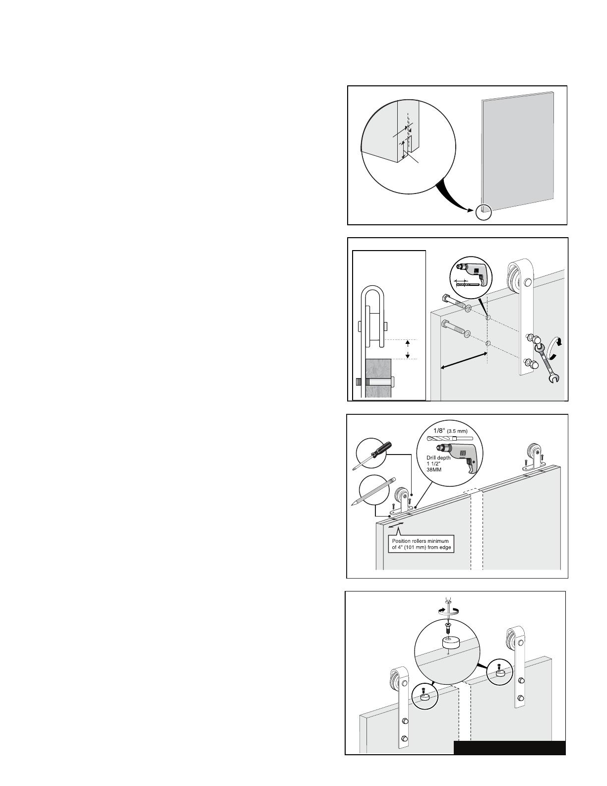
Mortice 1/4" wide x 3/4" deep groove centrally to the bottom
will ensure smoothness of door travel side-to-side and will
prevent the door from swinging in and out.
Step 1. Door Preparation
Note: K and Z Bar Planked
doors are pre-routed along the bottom and do not require door
preparation.
Note: A second, optional wall-mounted door guide has also been
provided in this kit should you not wish to mortice your door.
Mortice 1/4" wide x 3/4" deep groove
centrally to the bottom of the door for the use with the oor-mounted door
guide. This will ensure smoothness of door travel side-to-side and will
prevent the door from swinging in and out.
BARN DOOR HARDWARE KIT
ASSEMBLY INSTRUCTIONS
Step 1. Door Preparation
Note: K and Z Bar Planked are pre-routed along the
bottom and do not require door preparation.
A second, optional, wall-mounted door guide has also
been provided in this kit should you not wish to
mortice your door (See Step 12).
3/4
" (19 mm)
1/4"
(6.3 mm)
Step 3. Door Preparation - Anti-jump block Installation
Position each anti-jump block at least 1" from the edge of the
Straps. Tighten slightly to secure in place.
Step 2. Door Preparation – Strap Installation
Position each strap to the front of the door center to the
stile or a minimum of 2" from the edge of the door.
Cut a piece of cardboard 2" high and place between the
wheel (inner groove) and the top of the door to correctly
position the height of the straps.
Mark holes with a pencil and pre-drill 3/8" holes, then
secure into place. Repeat for second strap.
Centre to Stile or
minimum of 2" (51 mm)
drill out
3/8" (10mm)
2" (51 mm)
®
www.millikenmillwork.com
Mortice 1/4" wide x 3/4" deep groove centrally to the bottom
will ensure smoothness of door travel side-to-side and will
prevent the door from swinging in and out.
Step 2a. Door Preparation -
Strap Installation for Bent Strap
Position each strap to the front of the door center to the stile or a minimum
of 2" from the edge of the door.
Cut a piece of cardboard 2" high and place between the wheel (inner
groove) and the top of the door to correctly position the height of the
straps.
Mark holes with a pencil and pre-drill 3/8" holes, then secure into place.
Repeat from second strap.
Step 2b. Door Preparation -
Strap Installation for Top Mount
Position each roller a minimum of 4" from the edge of the door.
Mark the rst hole with a pencil and pre-drill 1/8" holes, then secure into
place. Mark the second hole with the roller in place to ensure the roller is
secure. Repeat for second roller.
BARN DOOR HARDWARE KIT
ASSEMBLY INSTRUCTIONS
Step 1. Door Preparation
Note: K and Z Bar Planked are pre-routed along the
bottom and do not require door preparation.
A second, optional, wall-mounted door guide has also
been provided in this kit should you not wish to
mortice your door (See Step 12).
3/4
" (19 mm)
1/4"
(6.3 mm)
Step 3. Door Preparation - Anti-jump block Installation
Position each anti-jump block at least 1" from the edge of the
Straps. Tighten slightly to secure in place.
Step 2. Door Preparation – Strap Installation
Position each strap to the front of the door center to the
stile or a minimum of 2" from the edge of the door.
Cut a piece of cardboard 2" high and place between the
wheel (inner groove) and the top of the door to correctly
position the height of the straps.
Mark holes with a pencil and pre-drill 3/8" holes, then
secure into place. Repeat for second strap.
Centre to Stile or
minimum of 2" (51 mm)
drill out
3/8" (10mm)
2" (51 mm)
®
www.millikenmillwork.com
Mortice 1/4" wide x 3/4" deep groove centrally to the bottom
will ensure smoothness of door travel side-to-side and will
prevent the door from swinging in and out.
Image for bent strap shown
Step 3. Door Preparation -
Anti-jump block installation
Position each anti-jump block at least 1" from the edge of the straps.
Tighten slightly to secure into place.


