Page is loading ...

Model 3162 Series
Field Generating
Pyramidal Horn
User Manual

ii |
ETS-Lindgren L.P. reserves the right to make changes to any product described
herein in order to improve function, design, or for any other reason. Nothing
contained herein shall constitute ETS-Lindgren L.P. assuming any liability
whatsoever arising out of the application or use of any product or circuit
described herein. ETS-Lindgren L.P. does not convey any license under its
patent rights or the rights of others.
© Copyright 2016 by ETS-Lindgren, Inc. All Rights Reserved. No part of this
document may be copied by any means without written permission from
ETS-Lindgren, Inc.
Trademarks used in this document: The ETS-Lindgren logo is a trademark of
ETS-Lindgren, Inc.
Revision Record
MANUAL,3162 HIGH GAIN PYRAMIDAL HORNS | Part #399286, Rev. D
Revision Description Date
A Initial Release November, 2004
B Update/edit September, 2005
C Update Electrical Specifications;
rebrand
November, 2008
D Updated Electrical Specifications
table
October, 2012
E Corrected model numbers on
page 7
June, 2016

| iii
Table of Contents
Notes, Cautions, and Warnings ................................................ v
1.0 Introduction .......................................................................... 7
Standard Configuration ............................................................................... 8
Angled Orientation ...................................................................................... 9
ETS-Lindgren Product Information Bulletin ............................................... 11
2.0 Maintenance ....................................................................... 13
Storage Recommendations ....................................................................... 13
Annual Calibration .................................................................................... 13
Service Procedures .................................................................................. 13
3.0 Specifications ..................................................................... 15
Electrical Specifications ............................................................................ 15
Physical Specifications ............................................................................. 15
4.0 Typical Data ........................................................................ 17
Antenna Input Power–Horizontal Polarization ........................................... 17
Antenna Input Power–Vertical Polarization ............................................... 18
Antenna Input Power–Horizontal and Vertical Polarization ........................ 19
Appendix A: Warranty ............................................................. 21

iv |
This page intentionally left blank.

| v
Notes, Cautions, and Warnings
Note: Denotes helpful information intended to
provide tips for better use of the product.
Caution: Denotes a hazard. Failure to follow
instructions could result in minor personal injury
and/or property damage. Included text gives proper
procedures.
Warning: Denotes a hazard. Failure to follow
instructions could result in SEVERE personal injury
and/or property damage. Included text gives proper
procedures.
See the ETS-Lindgren Product Information Bulletin for safety,
regulatory, and other product marking information.

vi |
This page intentionally left blank.

Introduction | 7
1.0 Introduction
The ETS-Lindgren Model 3162 Series Field Generating Pyramidal Horn was
developed to meet the following specifications for automotive EMC component
testing:
• GMW3097 (3162-01)
• ES-XW7T-1A278-AC (3162-01, 3162-02)
These tests require that the Equipment Under Test (EUT) be exposed to a
pulsed peak field level of 600 V/m at a distance of 100 cm from the front of the
horn when the EUT is placed on a metallic top test bench. At these frequencies it
is difficult and expensive to find amplifiers with high power ratings; and because
of near field gain compression, most horns fail to meet this specification at the
required test distance unless power in excess of 800 W is used. The
Model 3162 Series optimizes near field behavior, and produces a field level of
600 V/m with a 500 W amplifier.

8 | Introduction
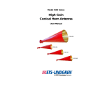
Standard Configuration
The standard configuration for the Model 3162 Series consists of one pyramidal
horn antenna with a coax-to-waveguide adapter.

Introduction | 9
Angled Orientation
Ford Motor Company is studying the benefits of a vertical orientation
of the horn with a slight angle or tilt. Contact Ford for permission prior
to using this set up.

10 | Introduction
The following graph illustrates the power requirements for vertical and horizontal
polarization at a 70 cm distance once the horn is angled.

Introduction | 11
ETS-Lindgren Product Information Bulletin
See the ETS-Lindgren Product Information Bulletin included with your shipment
for the following:
• Warranty information
• Safety, regulatory, and other product marking information
• Steps to receive your shipment
• Steps to return a component for service
• ETS-Lindgren calibration service
• ETS-Lindgren contact information

12 | Introduction
This page intentionally left blank.

Maintenance | 13
2.0 Maintenance
Before performing any maintenance,
follow the safety information in the
ETS-Lindgren Product Information
Bulletin included with your shipment.
Maintenance of the Model 3162 Series is
limited to external components such as
cables or connectors.
If you have any questions concerning
maintenance, contact ETS-Lindgren
Customer Service.
Storage Recommendations
When not in use, store the antenna in a dry area. Place the antenna on the floor
or a shelf with the side extensions perpendicular to the surface. If necessary, the
extensions may be removed for storage. If you remove the sides, make sure that
the contact area is clean prior to reassembling the antenna.
Annual Calibration
See the Product Information Bulletin included with your shipment for information
on ETS-Lindgren calibration services.
Service Procedures
For the steps to return a system or system component to ETS-Lindgren for
service, see the Product Information Bulletin included with your shipment.
WARRANTY

14 | Maintenance
This page intentionally left blank.

Specifications | 15
3.0 Specifications
Electrical Specifications
3162-01 3162-02
Frequency Range: 1.1 GHz–1.5 GHz 2.7 GHz–3.1 GHz
Input Impedance: 50 Ω 50 Ω
VSWR: 1.5:1 Typical
2:1 Maximum
1.5:1 Typical
2:1 Maximum
Maximum Continuous
Input Power:
550 W 500 W
RF Connector: Type N female Type N female
Physical Specifications
3162-01 3162-02
Length: 160.27 cm
63.1 in
79.2 cm
31.2 in
Width: 64.77 cm
25.5 in
44.2 cm
17.4 in
Height: 74.68 cm
29.4 in
58.4 cm
23.0 in
Weight: 23.6 kg
52.0 lb
10.0 kg
22.0 lb

16 | Specifications
This page intentionally left blank.

Typical Data | 17
4.0 Typical Data
Antenna Input Power–Horizontal Polarization
The following graph illustrates the power required to generate 600 V/m CW as
measured inside an actual automotive component EMC chamber.

18 | Typical Data
Antenna Input Power–Vertical Polarization
The following graph illustrates the power requirements for vertical polarization.
Data is proved at 1 m, 80 cm, and 70 cm distances.

Typical Data | 19
Antenna Input Power–Horizontal and Vertical Polarization
The following graph illustrates the power requirements for vertical and horizontal
polarization at a 70 cm distance. Data is proved at 1 m, 80 cm, and 70 cm
distances.

20 | Typical Data
This page intentionally left blank.
/