Johnson Controls E-Link Installation Instructions Manual
- Type
- Installation Instructions Manual

E-Link Gateway Installation Instructions 1
Applications
The E-Link Gateway provides Johnson Controls® and
YORK® mechanical equipment, such as chillers and
rooftop units, with Building Automation System (BAS)
networking connectivity. It is designed with three active
serial ports: Port 1 and Port 4 are used for BAS
networking, Port 2 is reserved for connecting to the
equipment, and Port 3 provides access for auxiliary
monitoring and control.
To simplify the installation and setup, the E-Link
Gateway comes pre-configured with a series of chiller
and rooftop equipment profiles that you can choose by
selecting the correct DIP switch settings.
Several E-Link Gateway models are available for
connection to various types of input voltage and
equipment. For chillers using the OptiView™ or
Latitude Micro Panel, the E-Link Gateway consists of a
single circuit board attached to four studs inside the
Micro Panel, using the accessory mounting kit. The
panel supplies 12 VDC input power, eliminating the
need for an external power supply.
For chillers using the IPU-II based Micro Panel, the
E-Link Gateway is installed inside the Micro Panel and
requires an additional transformer to supply power to
the E-Link Gateway. The transformer is included in the
E-Link IPU-II Installation Kit. (This kit is not available in
Europe. Use E-Link Gateway YK-ELNKE00-0.)
For other types of chillers, the E-Link Gateway is
packaged in its own enclosure. In addition to the E-Link
Gateway circuit board, a transformer is included inside
the enclosure that converts a 120- or 240-volt input to
24 VAC power.
North American Emissions Compliance
United States
Canada
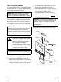
Installation
The E-Link Gateway is supplied as a circuit board that
can be installed directly into the equipment’s enclosure,
or can be supplied pre-mounted in an enclosure ready
for line voltage. Accessory mounting kits are used to
mount the E-link Gateway directly into OptiView
Latitude, and IPU-II based Micro Panels.
This equipment has been tested and found to
comply with the limits for a Class A digital device
pursuant to Part 15 of the FCC Rules. These limits
are designed to provide reasonable protection
against harmful interference when this equipment is
operated in a commercial environment. This
equipment generates, uses, and can radiate radio
frequency energy and, if not installed and used in
accordance with the instruction manual, may cause
harmful interference to radio communications.
Operation of this equipment in a residential area is
likely to cause harmful interference, in which case
the user will be required to correct the interference
at his/her own expense.
This Class (A) digital apparatus meets all the
requirements of the Canadian Interference-Causing
Equipment Regulations.
Cet appareil numérique de la Classe (A) respecte
toutes les exigences du Règlement sur le matériel
brouilleur du Canada.
IMPORTANT: Do not install the E-Link Gateway
directly into an equipment’s enclosure without the
use of an approved installation kit.
E-Link Gateway
Installation Instructions
Part No. 24-10404-9, Rev. D
Issued November 2, 2011
Supersedes April 29, 2011

E-Link Gateway Installation Instructions2
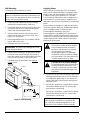
IMPORTANT: The E-Link Gateway is intended to
provide an input to equipment under normal
operating conditions. Use this E-Link Gateway only
as an operating control. Where failure or malfunction
of the E-Link Gateway could lead to personal injury
or property damage to the controlled equipment or
other property, additional precautions must be
designed into the control system. Incorporate and
maintain other devices, such as supervisory or
alarm systems or safety or limit controls, intended to
warn of or protect against failure or malfunction of
the E-Link Gateway.
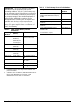
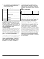
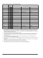
Table 1: YORK Chiller Models (Current
Production)
Board
Number
1
Language
(Native)
Chiller Model
031-02550 BACnet®,
Modbus®,
YORK Talk 2,
4,800 bits per
second (bps)
YCWL, YCUL, YCAL,
YLAA, YCRL, YLPA
031-01095 YORK Talk 2,
4,800 bps
YCAS, YCWS, YCRS
031-02478 YORK Talk 2,
4,800 bps
YCAV, YCIV, YVAA
031-01065 YORK Talk 2,
1,200 bps
YIA, YPC, YG, YB
031-01730 YORK Talk 3 YN, OM RETROFITS,
CR
031-02430 YORK Talk 3 YK, YT, YS, YR, YST,
YD, YMC
2
331-02496 BACnet® YPAL
YORK-003 Modbus RTU YEWS-D1, YEAS,
YGAS
2
1. Installing technician must verify board number in unit
prior to installation.
2. Software edition of YEWS-D1 (RHSYEWSD1) V1.08 or
later), YEAS (RHMASB V1.06 or later), YGAS
(RHMYGAS V1.03 or later) are supported.
Table 2: E-Link Gateway Product Code Numbers
Description Product Code
Numbers
E-Link with Serial Outputs (BACnet
Master-Slave/Token-Passing [MS/TP],
Modbus Remote Terminal Unit [RTU],
and N2)
YK-ELNK100-0
E-Link with LONWORKS® as an Output YK-ELNK101-0
E-Link with Serial Outputs in
Enclosure
YK-ELNKE00-0
E-Link with L
ONWORKS Output in
Enclosure
YK-ELNKE01-0
E-Link OptiView/Latitude Panel
Installation Kit
YK-ELNKOLK-0
E-Link IPU-II Panel Installation Kit
(not available in Europe)
YK-ELNKSTK-0

E-Link Gateway Installation Instructions 3
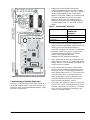
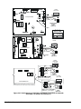
Mounting
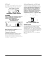
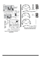
OptiView Panel Installation
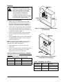
1. Attach the E-Link Gateway board to the studs
provided inside the chiller enclosure (Figure 1 or
Figure 2), using the four screws and washers
provided in the OptiView/Latitude installation kit.
2. Connect the communications cable (included with
the kit) from Port 2B on the E-Link Gateway to J2
on the OptiView Micro Panel. Ensure that wires are
connected according to Table 3.
3. Check for stray wire strands, which could cause
short circuits, and ensure all components are
secure.
4. Connect the BAS network to Port 1 (if the protocols
are transported by RS-485) or Port 4 (if the BAS
network is L
ONWORKS).
Note: For RS-485 2-wire operation, connect a 100
ohm 1 W resistor between COM and the E-Link
Gateway’s TB5 COM (see Figure 24).
5. Ensure jumper JP27 is set for RS-232 (see
Figure 20).
6. Connect the power harness (included with the kit)
from J2 on the E-Link Gateway to J21 on the
Optiview Micro Panel (see Figure 20).
The E-Link Gateway is now ready to be configured
using Quick Start; see the Commissioning a Standard
Application section in this document.
!
WARNING: Risk of Electric Shock.
Disconnect or isolate all power supplies
before making electrical connections.
More than one disconnect or isolation
may be required to completely de-
energize equipment. Contact with
components carrying hazardous voltage
can cause electric shock and may result
in severe personal injury or death.
Table 3: OptiView Wiring - E-Link Port 2B
E-Link Port 2B OptiView Port Wire Color
RX GTX Black
TX GRX Red
REF N/A Shield/Drain
Table 4: BAS Wiring - E-Link Port 1
E-Link Port 1 BAS Wire Color
++White
--Blue
REF REF Black
FIG:Opti_Pnl
Figure 1: OptiView Micro Panel Connected to
E-Link Gateway
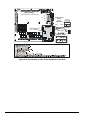
FIG:Opti_Pnl1
Figure 2: OptiView Micro Panel for YMC
2
Connected to E-Link Gateway

E-Link Gateway Installation Instructions4
IPU-II Panel Installation
(Installation Kit Not Available in Europe)
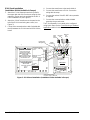
1. Attach the E-Link Gateway board to the panel in
the upper right side of the enclosure using the four
expansion screws and nuts provided in the IPU-II
Panel Installation Kit (see Figure 3).
2. Attach the 24 VAC transformer to the panel to the
left of the E-Link board using two screws (see
Figure 3).
3. Connect the communications cable (included with
the kit) between the E-Link board and IPU-II Micro
board.
4. Connect the transformer to the terminal block.
5. Connect the transformer to E-Link. Secure the
wiring with tie-wraps.
6. Connect the resistor if the RS-485 2-wire operation
is required.
7. Connect the communications cable shielded
ground to the ground screw.
The E-Link Gateway is now ready to be configured
using Quick Start; see the Commissioning a Standard
Application section in this document.
Micro Boar
d
24 VAC
Transforme
r
Expansion
Nut
Expansion
Nut
Screw
Sheet
Metal
Screw
Resisto
r
Secondar
y
Powe
r
Wiring
Harness
Tie
Wrap
T
B5
TB 2
E-LIN
K
Transforme
r
Secondar
y
Ground
Communication
Wiring Harness
Com
Ground
T B 1
T B 5
The Resistor is used for BAS
RS485 2 Wire Connection.
Connect one end of the
Resistor to the COM o
f
TB5 (24 VAC) and the othe
r
to Port 1 COM.
Use this resistor only if the
BAS wiring utilizes a 2 Wire
communication trunk
Communication Wiring Harness:
Connect to Micro Board
TB1 as Follows:
Wire Color / Terminal
Red / +
Black / -
+
-
REFSHLD
TB 1 RS485
F
I
G
:
I
P
U
p
n
l
i
n
s
t
Terminal block location
for YCAL-D, YCAL-E, and YLAA.
Terminal block location
for YCAL-C, YCWL, and
Primary Powe
r
Wiring Harness
TB2
TB5
Y
CUL-C.
Figure 3: IPU-II Panel Installation (Installation Kit Not Available in Europe)

E-Link Gateway Installation Instructions 5
Other Chiller Panel Installation
For all other applications, the E-Link Gateway includes
an optional enclosure. The optional enclosure does not
include communication cables due to the variety of
types and lengths that may be required.
The E-Link Gateway can be mounted as a stand-alone
enclosure either on the outside surface of the chiller
Micro Panel (close coupled), or on a smooth surface
within close proximity of the chiller panel enclosure.
For mounting on a Micro Panel, the line voltage power
is supplied by a power source in the Micro Panel.
Mounting on a Micro Panel
To mount the E-Link Gateway on a Micro Panel:
1. Disconnect power to the chiller Micro Panel.
2. Make sure the E-link Gateway enclosure fits
properly and that no obstructions, such as internal
boards, switches, or external conduit, prevent
mounting or servicing of the panel. See Figure 4 for
examples of good mounting locations.
3. Locate and remove the two plastic caps in the
bottom of the E-Link Gateway enclosure.
4. Mark an appropriate place on the enclosure for a
matching set of knock out holes. Mark and drill, or
punch, two holes in the Micro Panel.
5. Using two bulkhead pipe couplers, attach the
E-Link Gateway enclosure to the Micro Panel.
6. Complete wiring as described in the Applying
Power section in this document.
Note: Use of bulkhead pipe couplers provides
sufficient clearance to allow removal of the E-Link
Gateway cover.
IMPORTANT: Never install the E-Link Gateway
outside the confines of a building unless within
another enclosure rated IP 65/NEMA 4x or higher.
IMPORTANT: Make sure that the cover is securely
fastened to the enclosure and the internal ground
wire is attached before placing the Gateway in
operation. These steps help to minimize Radio
Frequency Interference (RFI) from being generated
and picked up.
!
WARNING: Risk of Electric Shock.
Disconnect or isolate all power supplies
before making electrical connections.
More than one disconnect or isolation
may be required to completely
de-energize equipment. Contact with
components carrying hazardous voltage
can cause electric shock and may result
in severe personal injury or death.
IMPORTANT: When attaching the E-Link Gateway
to a Micro Panel, ensure the E-Link Gateway does
not impede access to other components.
IMPORTANT: Be careful not to damage the E-link
Gateway or Micro Panel’s circuit boards during the
installation. Protect all circuit boards from metal
chips, which may cause short circuits if left on the
boards at startup.
E-LINK
Enclosure
YORK Chiller
Micro Panel
Alternative
Mounting
Locations
FIG:MntEqu ip
Figure 4: Mounting on the Equipment

E-Link Gateway Installation Instructions6
Wall Mounting
To mount the E-Link Gateway on a wall:
1. Check for proper clearances for the necessary
electrical and communications cable runs.
2. Ensure that power and communications wiring is in
compliance with all local, national, and regional
codes, and customer requirements.
3. Select a suitable location and mark the anchor
points. Ensure that the enclosure is level. See
Figure 5 for an example.
4. Drill the appropriate holes in accordance with the
type of wall anchor used.
5. Install the enclosure on the wall.
6. Check that the mounting is secure and the wiring
connections are correct and tight. Check that no
loose wire strands or other metal objects that could
cause a short circuit are on the circuit board.
7. Complete wiring as described in the Applying
Power section.
Applying Power
When using an enclosure type of E-Link Gateway,
power can be supplied from either a separate power
supply or the main terminal strip in the chiller panel.
Locate the power source within 0.9 m (3 ft) of the
E-Link Gateway, and protect it with a suitable fuse or
circuit breaker. Ensure the power is supplied from a
dedicated source and not controlled by a programmed
switch.
If the enclosure is mounted on a wall, the wiring from
the power source to the E-Link Gateway must always
run in a suitable conduit. To obtain the best
Electromagnetic Interference (EMI) and
Electromagnetic Compatibility (EMC) performance,
ensure that the conduit is bonded to the metal of both
enclosures. Scraping the paint around the knockouts
usually helps provide a better electrical connection
between the joining parts.
1. Connect a 1.29-1.02 mm (16-18 AWG) wire from a
reliable ground reference to the E-Link Gateway’s
incoming power ground lug. Do not remove the
existing wire that connects the ground lug to the
enclosure cover.
2. On 120 VAC applications, connect the Hot wire to
TB2 and the Neutral wire to TB1. Connect the
ground wire to a ground lug.
On 240 VAC applications, connect the Hot wire to
TB3 and the Neutral wire to TB1. Connect the
ground wire to a ground lug.
IMPORTANT: When wall mounting, make sure
there is no interference with other components in the
near vicinity. Use appropriate conduit to connect the
power and communications wiring.
IMPORTANT: Be careful not to damage the circuit
boards during installation.
YORK Chiller
Micro Panel
Template for Mounting
on a Wall
Conduit
E-Link
Enclosure
FIG:WllMnt
Figure 5: Wall Mounting
!
WARNING: Risk of Electric Shock.
Disconnect or isolate all power supplies
before making electrical connections.
More than one disconnect or isolation
may be required to completely
de-energize equipment. Contact with
components carrying hazardous voltage
can cause electric shock and may result
in severe personal injury or death.
!
CAUTION: Risk of Property Damage.
Do not apply power to the system before
checking all wiring connections. Short
circuited or improperly connected wires
may result in permanent damage to the
equipment.
IMPORTANT: Use copper conductors only.
Make all wiring connections in accordance with
local, national, and regional regulations. Do not
exceed the E-Link Gateway’s electrical ratings.

E-Link Gateway Installation Instructions 7
Commissioning a Standard Application
Once the E-Link Gateway has been mechanically and
electrically installed (that is, it has been located in its
enclosure, wired, and terminated appropriately), it may
be Quick Commissioned.
1. Apply power and verify that the red power
Light-Emitting Diode (LED) on the IPU-II board is
on. Make sure the T-switch is set to OFF, and then
set the required Media Access Control (MAC)
address. Set the MAC address in accordance with
the system integrator to ensure that a unique
address is used. If any non-standard setup is
required, refer to the E-Link Commissioning and
Troubleshooting Guide (LIT-12011238) for more
details.
2. Based on the equipment to be integrated (see
Table 8) and the required BAS output protocol (see
Table 9), select the appropriate settings on
GROUP A and GROUP B switches. For equipment
points lists, refer to the Johnson Controls Portal
(Products and Services>Delivery>Products/
Service Field Support>Equipment
Integration>YORK Equipment Data Maps).
3. Press, hold a few seconds, then release the push
button shown in Figure 11. The status LED flashes
quickly. After the E-Link Gateway re-initializes, the
commissioning is complete.
4. When commissioning a
LONWORKS BAS output
protocol, disconnect the BAS network and cycle
the power on the E-Link Gateway to activate the
Quick Start and the
LONWORKS FTT10 ProtoCessor.
The ProtoCessor does not recognize the push
button as a trigger to reset and load the correct
conversion file. Wait a minimum of 10 minutes
before reconnecting the BAS network.
5. Check the E-Link Gateway’s LEDs. First, check the
STATUS LED; if the E-Link Gateway has no errors,
it flashes continuously (1/2 second on, 1/2 second
off). If the LED is not flashing continuously, see
Table 6 for possible reasons.
FIG:PwrConn
Figure 6: Power Connection Shown as 120 VAC
Table 5: Allowable MAC Addresses
Protocol Max Allowable Switch
Settable MAC
Addresses
BACnet MS/TP 1 – 127
N2 1 – 127
Modbus RTU 1 – 127

E-Link Gateway Installation Instructions8
6. Place the equipment in remote operating mode to
accept commands from the E-Link Gateway. Refer
to the equipment installation literature for the
proper configuration settings.
For all chillers that use the YORK Talk protocols, check
that the Port 2 communication LEDs, Red (TX) and
Green (RX), are flashing. This scenario indicates that
the chiller panel is being polled and is responding. See
Figure for the location of Port 2 communication LEDs.
What You Should Know before
Using Quick Starts
The E-Link is designed to use a set of predefined data
maps to associate equipment data with a set of fixed
BAS network variables. You are not able to make any
field changes to these data maps; attempting to do so
results in the automatic reversal of any edits that you
may have made. For any field patches, refer to your
local FSC (Field Support Center) for guidance.
The data maps used by the E-Link Gateway are based
on a collection of version controlled equipment point
lists, which are supplied by the equipment business for
the purpose of integrating equipment into BAS
networks. Unless noted otherwise, the equipment’s
data is available in these supported BAS protocols:
BACnet MS/TP, N2,
LONWORKS, and Modbus RTU.
The first release of the E-Link was positioned to
provide the equivalent functionality as offered by the
YORK MicroGateway. That release requires you to
reference point lists which are version J or earlier. All
subsequent E-link releases use point lists version K or
later.
Quick Starts 1 through 16 all use the J version point
lists, whereas Quick Starts 17 through 33 use the K
version. The primary difference between the two
categories is that Quick Starts 1 through 16 have
limited network visible points. In this case, the available
points are those which were originally available at the
time when the MicroGateway was first released.
Quick Starts 17 and higher offer a much richer
equipment point compliment that is more reflective of
what the equipment currently makes available today.
These Quick Starts also create profiles that use more
descriptive BACnet point names, use engineering
units, and follow the BACnet Testing Laboratories™
(BTL) guidelines for compliance as a B-ASC controller.
In most cases, using a Quick Start that corresponds to
the equipment being integrated is sufficient to configure
the E-Link Gateway for operating on the BAS network;
however, in some circumstances, you will be required
to provide further customizing by connecting a laptop
computer onto Port 3 and then accessing the User
Reports (refer to the E-Link Gateway Commissioning
and Troubleshooting Technical Bulletin [LIT-12011238]
for more information).
Table 6: LED Status indication
Flash Rate Status LED Indication
LED Off No database configuration is loaded, or no
input power is present.
1 Flash Terminal mode has been invoked (Switch
T is on).
2 Flashes An equipment to E-Link communications
error has occurred.
3 Flashes A Quick Start has a configuration error.
LED On No errors with custom/field modified
application.
Flashing
Continuously
No errors with factory standard
application.
Table 7: E-Link Releases
Firmware/Database Revision Point Lists
SSM4567 JCF0003BL.BIN J and earlier only
SSM4567 JCF0008BL.BIN J and earlier, or K

E-Link Gateway Installation Instructions 9
Table 8: Equipment Quick Start Selections
APP Group Switch A Equipment Profile Quick Starts
Switch Settings 32168421Functionality
1
1
0 0 0 0 0 1 YK with SSS Imperial (YORK Talk-III) J version points
2 0 0 0 0 1 0 YK with VSD Imperial (YORK Talk-III) J version points
3
1
0 0 0 0 1 1 YT with SSS Imperial (YORK Talk-III) J version points
4 0 0 0 1 0 0 YT with VSD Imperial (YORK Talk-III) J version points
5
1
0 0 0 1 0 1 YS / YR with SSS Imperial (YORK Talk-III) J version points
6
1
0 0 0 1 1 0 YK with SSS Metric (YORK Talk-III) J version points
7 0 0 0 1 1 1 YK with VSD Metric (YORK Talk-III) J version points
8
1
0 0 1 0 0 0 YT with SSS Metric (YORK Talk-III) J version points
9 0 0 1 0 0 1 YT with VSD Metric (YORK Talk-III) J version points
10
1
0 0 1 0 1 0 YS / YR with SSS Metric (YORK Talk-III) J version points
11 0 0 1 0 1 1 YORK Talk II, 1200, 1 Section (YORK Talk-II) J version points
12 0 0 1 1 0 0 YORK Talk II, 4800, 1 Section (YORK Talk-II) J version points
13
2
0 0 1 1 0 1 YORK Talk II, 4800, 2 Sections (YORK Talk-II) J version points
14 0 0 1 1 1 0 YD Imperial (YORK Talk-III) J version points
15 0 0 1 1 1 1 YD Metric (YORK Talk-III) J version points
16 0 1 0 0 0 0 ECO2 / YPAL / S100 (BACnet MS/TP via an IPU-I)
17 0 1 0 0 0 1 YK with SSS Imperial (YORK Talk-III) K version points
18 0 1 0 0 1 0 YK with VSD Imperial (YORK Talk-III) K version points
19 0 1 0 0 1 1 YT with SSS Imperial (YORK Talk-III) K version points
20 0 1 0 1 0 0 YT with VSD Imperial (YORK Talk-III) K version points
21 0 1 0 1 0 1 YS / YR with SSS Imperial (YORK Talk-III) K version points
22 0 1 0 1 1 0 YK with SSS Metric (YORK Talk-III) K version points
23 0 1 0 1 1 1 YK with VSD Metric (YORK Talk-III) K version points
24 0 1 1 0 0 0 YT with SSS Metric (YORK Talk-III) K version points
25 0 1 1 0 0 1 YT with VSD Metric (YORK Talk-III) K version points
26 0 1 1 0 1 0 YS / YR with SSS Metric (YORK Talk-III) K version points
27 0 1 1 0 1 1 YST Imperial (YORK Talk-III) K version points
28 0 1 1 1 0 0 YIA Imperial (YORK Talk-III) K version points
29 0 1 1 1 0 1 YST Metric (YORK Talk-III) K version points
30 0 1 1 1 1 0 YIA Metric (YORK Talk-III) K version points
31 0 1 1 1 1 1 YEWS-D1/YEAS/YGAS (Modbus native)
32 1 0 0 0 0 0 YD Imperial (YORK Talk-III) K version points
33 1 0 0 0 0 1 YD Metric (YORK Talk-III) K version points
34 1 0 0 0 1 0 YMC2 Imperial (YORK Talk-III) K version points
35 1 0 0 0 1 1 YMC2 Metric (YORK Talk-III) K version points
63 1 1 1 1 1 1 Reserved for Field adjustments
1. A Quick Start that references a Solid State Starter (SSS) is also applicable to a mechanical starter.
2. Two sections are required for equipment equipped with three or more compressors, or two systems.

E-Link Gateway Installation Instructions10
Table 9: BAS Output Protocol Quick Start Selections
APP Group
Switch B
Output Protocol Quick Starts
Switch Settings 8421Port 1 Port 3 Port 4
0
1
1. When making edits to User Report 4 (Port Configuration), Group Application Switch B must be set to zero. This setting
ensures that the edits are stored. Otherwise, the edits are overwritten to the default values assigned to the particular Group
Switch B setting the next time E-Link is reset, or power is cycled. Edits made in any other User Reports do not require
alterations to either bank of Group Application switches. For standard set-up, not requiring modifications via User Report 4,
use application switch B, settings 1 to 14.
0000MS/TP, AUTO, N, 8, 1 Modbus, 19,200, N, 8, 1 Terminal
1
2, 5
2. The Terminal setting on Port 4 is restricted for factory use only.
To comply with the LONMARK® specification, all data transmitted on the LONWORKS network must be expressed in SI units
(metric units). The L
ONWORKS ProtoCessor performs no unit conversions; it assumes that the data supplied is already
correctly expressed.
0001MS/TP, AUTO, N, 8, 1 Modbus, 19,200, N, 8, 1 Terminal
2
2, 5
0010MS/TP, AUTO, N, 8, 1 Modbus, 19,200, N, 8, 2 Terminal
3
2, 5
0011MS/TP, AUTO, N, 8, 1 N2, 9,600, N, 8, 1 Terminal
4
2, 5
0100N2, 9,600, N, 8, 1 MS/TP, 38,400, N, 8, 1 Terminal
5
2, 5
0101Modbus, 19,200, N, 8, 1 MS/TP, 38,400, N, 8, 1 Terminal
6
2, 5
0110Modbus, 19,200, N, 8, 2 MS/TP, 38,400, N, 8, 1 Terminal
7
2, 5
0111Modbus, 9,600, E, 8, 1 MS/TP, 38,400, N, 8, 1 Terminal
8
2, 5
1000Modbus, 9,600, N, 8, 1 MS/TP, 38,400, N, 8, 1 Terminal
9
3, 5, 6
3. Use Quick Start 9 and 11 if the equipment is supplying the data in SI units (the E-Link is not required to perform any
conversions, so it operates in pass-through mode).
1001N2, 9,600, N, 8, 1 Modbus, 19,200, N, 8, 1 L
ONWORKS – Pass through
10
4, 5,
6
4. Use Quick Start 10 and 12 if the equipment is supplying the data in Imperial units and the E-Link is required to convert these
units into SI.
5. Setting Switch T = ON, on the MAC address, forces TERMINAL mode of Port 3, at 57,600 baud, N, 8, 1. This setting is only
required to debug the E-Link Gateway’s operation, or access the User Reports.
6. Select Quick Starts 9 and 10 when connecting the E-Link Gateway to an ECO2 unit.
1010N2, 9,600, N, 8, 1 Modbus, 19,200, N, 8, 1 L
ONWORKS – Conversion
11
3, 5
1011Modbus, 19,200, N, 8, 2 N2, 9,600, N, 8, 1 LONWORKS – Pass through
12
4, 5
1100Modbus, 19,200, N, 8, 2 N2, 9,600, N, 8, 1 LONWORKS – Conversion
13
2, 5
1101Modbus, 9,600, E, 8, 1 Modbus, 19,200, N, 8, 2 Terminal
14
2, 5
1110MS/TP, 38,400, N, 8, 1 N2, 9,600, N, 8, 1 Terminal
15
7
7. Quick Starts 15 on APP Group B, and 63 on APP Group A, are reserved for field adjustments.
1111Reserved Reserved Terminal

E-Link Gateway Installation Instructions 11
Wiring
Install the wiring so it does not cause a hazard, and is
protected against electrical and mechanical damage.
Power
The E-Link Gateway circuit board is powered from
either a 12 VDC, or a 24 VAC, Class 2 power source.
When used with an OptiView chiller, the Micro Panel
supplies low-voltage power via a power harness
supplied by the OptiView/Latitude installation kit. If the
E-Link Gateway circuit board is installed in its own
enclosure, a transformer is included in the enclosure.
Line voltage may be supplied using an external power
source, or drawn from the input voltage terminal strip
inside the equipment. Be sure the capacity of the
power conductors supplying the equipment is rated for
the additional power (VA) required by the E-Link
Gateway. Use a wire that is one size larger than
required for the amperage draw (maximum 400 mA) to
connect the line voltage feed to the E-Link Gateway.
For the line voltage power source, use a dedicated line
(with a separate fuse) that is isolated (using a control
transformer) from other equipment in the plant room
that may generate Electromagnetic Interference (EMI).
Grounding
For the enclosure style, a ground wire must be
connected directly to the enclosure supply power
ground lug at the point of entry. A small label (Figure 7)
identifies this grounding point. This ground wire should
be connected through a continuous ground circuit to
the incoming ground at the source transformer.
Note: Besides providing safety protection, the ground
connection plays an extremely important part in the
operation of the communication circuitry.
Protection of Communication Ports
When using RS-485 technology, it is possible that
electrical disturbances, such as voltage spikes, can
damage a circuit board. The E-Link Gateway includes
tranzorbs on each RS-485 port to protect against
damaging electrical spikes and stray voltage.
The equipment panel should also be equipped with
protection against electrical disturbances. Whereas
OptiView Micro Panels are equipped with onboard
tranzorbs, other equipment panels may require the
addition of an external board. Refer to the equipment
documentation for details. Port 1 of the E-Link Gateway
is also electrically isolated, providing a means of
mitigating common mode voltage induced problems.
High Noise Environments
Electrical equipment that employs high speed
switching circuits (Variable Speed Drives [VSD], Solid
State Starters [SSS], and computing equipment)
generates Electromagnetic Interference (EMI) noise
and Radio Frequency Interference (RFI), which can
generate transient voltage between ground points in
the communication wiring. The RS-485 circuitry is
designed to withstand some low transient voltage, but if
this difference exceeds certain limits, it can
permanently damage the RS-485 circuitry.
!
WARNING: Risk of Electric Shock.
Disconnect or isolate all power supplies
before making electrical connections.
More than one disconnect or isolation
may be required to completely
de-energize equipment. Contact with
components carrying hazardous voltage
can cause electric shock and may result
in severe personal injury or death.
!
CAUTION: Risk of Property Damage.
Do not apply power to the system before
checking all wiring connections. Short
circuited or improperly connected wires
may result in permanent damage to the
equipment.
IMPORTANT: Make all wiring connections in
accordance with local, national, and regional
regulations.
!
WARNING: Risk of Electric Shock.
Ground the E-Link Gateway enclosure
according to local, national, and regional
regulations. Failure to ground the E-Link
Gateway may result in electric shock and
severe personal injury or death.
IMPORTANT: Ensure that the Micro Panel and the
E-Link Gateway are powered from a source with a
true earth ground.
GRD
F
I
G
:
G
r
n
d
Figure 7: Grounding Label

E-Link Gateway Installation Instructions12
Electrical Noise Mitigation to Equipment
The likelihood of transient voltage is greatly reduced if
the E-Link Gateway is close-coupled to the Micro
Panel. Close-coupling requires that the E-Link
Gateway and Micro Panel share the same line voltage
power source and are physically close to one another.
Typically, the E-link Gateway is mounted on the Micro
Panel enclosure. This scenario ensures a short
communication cable, which is usually protected
entirely within the two enclosures.
Electrical Noise Mitigation
for E-Link to BAS
When the E-Link is used in an electrically hostile
environment (for example, with VSD-enabled
equipment), a double-shielded cable should be used to
help mitigate the adverse effects electrical noise can
have on the system. The double-shielded cable should
connect the E-Link’s BAS port (Port 1 or Port 4) to the
next controller(s) in the daisy-chained network.
The outer shield of the double-shielded cable should
be grounded directly at the low noise end (the end
most distant from the VSD), and ideally, indirectly
through an appropriate capacitor at the high noise end
(the end closest to the VSD). If a capacitor is not
available, the outer shield may be left unconnected, or
tied directly to ground. The best results on the site
determine the specific termination strategy employed.
The inner shield of the double-shielded cable should be
grounded directly at the low noise end (the end most
distant from the VSD), and left open at the high noise
end (the end closest to the VSD).
Types of Communication Ports
The E-Link Gateway uses three communication
protocols to connect to other devices: RS-485 and FFT
are used for multi-drop networking, whereas RS-232 is
primarily used for point-to-point connectivity.
RS-485
The RS-485 standard uses three conductors to
connect network nodes: two signal wires and a
reference. The E-Link Gateway uses either a third wire
for the reference or the building’s infrastructure. The
wiring method depends on the port being used: an
electrically isolated Port 1 typically uses a third wire,
whereas Ports 2 and 3 normally use chassis or building
ground for the reference.
Setup and Adjustments
There are a number of settings that you may make on
an E-Link Gateway or to the connected equipment.
Network Termination
Terminate all End-of-Line (EOL) devices at either end
of the RS-485 bus (that connect to only one set of
RS-485 network wires). EOL termination provides
biasing of the network, and assists in returning the
signal to a normal state in the event of voltage
transients. If the E-link Gateway happens to be the
end-of-line device, terminate the network by setting the
EOL switch located above each of the
E-Link Gateway’s RS-485 ports to the ON position.
Media Access Control (MAC) Address
The E-Link Gateway’s network hardware address is set
on a single 8-way DIP switch. Switch 8, the T switch, is
reserved to invoke Terminal mode on Port 3, leaving
the remaining 7 switches for setting the address. Refer
to the E-Link Gateway Commissioning and
Troubleshooting Technical Bulletin
(LIT-12011238) for more details.
The network address is binary weighted, allowing you
to set up to 127 unique addresses.
APP Group A
APP Group A uses a 6-way DIP switch to select the
desired equipment’s profile. This switch is also binary
weighted, allowing up to 63 unique selections.
IMPORTANT: Do not run communication cables in
close proximity to, or parallel with, high-voltage
power cables (maintain at least 457.2 mm [18 in.] of
separation, or use a grounded metal conduit).
IMPORTANT: Ensure that the EOL switches are
not set to the ON position for controllers that do not
terminate the RS-485 network.
Figure 8: RS-485 EOL Switches
Figure 9: MAC Dip Switch

E-Link Gateway Installation Instructions 13
APP Group B
APP Group B uses a 4-way DIP switch to select the
desired output protocol. This switch is also binary
weighted, allowing up to 15 unique selections.
Push Button
The E-Link Gateway uses a push button (Figure 11) as
a means of activating any user selections on APP
Group A and APP Group B switches.
Note: Refer to the E-Link Gateway Commissioning
and Troubleshooting Technical Bulletin
(LIT-12011238) for more details.
Equipment Configuration
Different pieces of equipment sometimes require a
specific hardware configuration (jumper/switch
settings) to enable communication with the E-Link
Gateway. Refer to the equipment’s installation literature
for the proper configuration settings.
Setting the Rotary Switch on Chiller Panels
Some Micro Panels use a rotary switch to set their
YORK Talk II address (YORK Talk address = Rotary
Switch setting + 1). Since the E-Link Gateway uses a
one-to-one relationship with the chiller panel, this
switch is normally set to 0 (YORK Talk address 1).
However, in a master/slave configuration, set the
master Micro Panel rotary switch to 0, and the slave
Micro Panel to 1. If the chiller Micro Panel is not
equipped with a rotary switch, the YORK Talk address
may be set using the Micro Panel keypad. In most
cases, you can configure the setting, but some models
are fixed and cannot be changed (refer to the
equipment documentation for specific details).
Network Topology
The E-Link Gateway has three serial communications
ports and an optional
LONWORKS port to connect
equipment to a BAS system. Port 1 and Port 4 are
designed as the BAS ports, with Port 1 used to support
all RS-485 based communication protocols, and Port 4
used for
LONWORKS connectivity with the addition of a
LONWORKS ProtoCessor module.
Note: See Figure 24 and Figure 25 for additional
information.
Figure 10: APP A and APP B DIP Switches
Figure 11: E-Link Gateway Push Button
FIG:ChlRot
Figure 12: Micro Panel Rotary Switch

E-Link Gateway Installation Instructions14
Figure 13: E-Link Gateway Component
Identification
COMMUNICATION CABLE
(OptiView / Latitude)
POWER HARNESS
(OptiView)
4 #8 NYLON WASHERS
(OptiView / Lattitude)
POWER HARNESS
(Latitude)
3/8 in. Screw
8 x 32
(OptiView)
2 Position
Connector
4 Position
Connector
4 Position
Connector
4 Position
Connector
Screw
Tap Thread
M4 x 32 mm
(Latitude)
FIG:OptiVwKt
YMC2
COMMUNICATION CABLE
(OptiView)
YMC2
POWER HARNESS
(OptiView)
4 Position
Connector
4 Position
Connector
YMC2 Communication Cable
Figure 14: E-Link OptiView/Latitude
Installation Kit (YK-ELNKOLK-0)

E-Link Gateway Installation Instructions 15
Secondary
24
V
AC
Primary
120
V
AC
100 OHM
Expansion
Nut
Expansion
Nut
Screw
Sheet
Metal
Screw
24 VAC
Power
Transformer
Primary
Power
Wiring
Harness
Communication
Wiring Harness
Resistor
Secondary
Power
Wiring
Harness
Tie
Wrap
FIG:IPUII-Kt
Figure 15: E-Link IPU-II Panel Installation Kit
(YK-ELNKSTK-0 Contents)
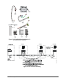
Unit #2
Last Unit
P
O
R
T
3
R
S
4
8
5
P
O
R
T
3
R
S
4
8
5
+
-
C
M
S
H
L
D
Unit #1
PORT 3 RS485
+
-
C
M
S
H
L
D
+ - C M SH LD
+ - C
M SHLD
FIG:BAS_Shld
Figure 16: BAS Trunk Shield Wiring

E-Link Gateway Installation Instructions16
UI7
TB7
031-01065-xxx
BLUE
WHITE
SHIELD
Jumper
BLUE
WHITE
(Open)
BLUE
WHITE
TB1
NOTE:
If the EPROM used in the board is dated prior
to 11/2000, the chiller ID is fixed at 0.
If the EPROM used is dated after 11/2000, the chiller
ID is software selectable through the micro panel
SHIELD
BLUE
WHITE
(Open)
031-02050-000
TB1
TB6
NOTE:
The chiller ID is software-selectable through the
micro panel keypad. Set the Chiller ID to 0 to make network
address to 1.
BLUE
WHITE
SHIELD
BLUE
WHITE
(Open)
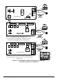
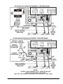
FIG:ELnk _YrkTlk
Equipment Connections
Figure 17: E-Link Gateway to YORK Talk II Equipment Connections
(See Table 1 for board cross-reference.)


E-Link Gateway Installation Instructions18
Equipment Cable
York Talk 2
RS485
(4800 baud)
COM 1
COM 2
Jumper
Equipment Cable
York Talk 2
RS485
(4800 baud)
SHIELD
+
-
C
O
M
S
H
L
D
P
O
R
T
2
A
R
S
4
8
5
(Open)
E-Link
VGA
PL20 COM 1
Equipment Cable
York Talk 2
RS485
(4800 baud)
Jumpers
SHIELD
P
O
R
T
2
A
R
S
4
8
5
(Open)
E-Link
+RX
NOTE:
Requires ISN EPROMs in locations U4 and U5.
The transfer rate on the chiller must be set to 4800 baud.
Frick RWBII Plus
Jumpers
Jumpers
RWBII Rev. B and Lower
+RX
Jumpers
RWBII Rev. C and Higher
U5
U4
Port 2
Port 1
SHIELD
P
O
R
T
2
A
R
S
4
8
5
(Open)
E-Link
SHIELD
P
O
R
T
2
A
R
S
4
8
5
(Open)
E-Link
Equipment Cable
York Talk 2
RS485
(4800 baud)
Frick Q2 Board
Frick Q3 Board
P
O
R
T
2
A
R
S
4
8
5
E-Link
+
_
C
O
M
S
H
L
D
+
-
C
O
M
S
H
L
D
+
-
C
O
M
S
H
L
D
+
-
C
O
M
S
H
L
D
FIG:ELnk_YrkTlk_3
Figure 19: E-Link Gateway to YORK Talk II Equipment Connections (Continued)
(See Table 1 for board cross-reference.)

E-Link Gateway Installation Instructions 19
Note: Enabling any of
the Latitude’s PRINT
functions will disrupt
BAS/E-Link
communications.
See YORK Equipment
Form 201.21-NMx in the
Installation, Operation &
Maintenance (IOM)
Air-Cooled Screw Liquid
Chillers manual for more
information.
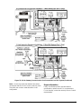
Note: JP1 on the
031-02478-xxx board
must be set to the
RS485 position when
the E-Link BAS
communication is
required.
Equipment Cable
York Talk 3
Rs232
Optiview Microboard
031-01730-XXX
SHIELD
P
O
R
T
2
B
R
S
232
TX
RX
COM SHLD
(Open)
E-Link
E-Link
+12 VDC
SHIELD
(Open)
Equipment Cable
York Talk 2
RS485
(4800 baud)
SHIELD
+
-
C
O
M
S
H
L
D
P
O
R
T
2
A
R
S
4
8
5
(Open)
E-Link
031-02478-xxx
1
2
3
4
5
Latitude
J16
E-Link
Power
E-Link
+12 VDC
P
O
R
T
2
A
R
S
4
8
5
E-Link
+
_
C
M
S
H
L
D
P
O
R
T
2
B
R
S
232
E-Link
TX
RX
COM
SHLD
Equipment Cable
York Talk 3
Rs232
Optiview Microboard
031-02430-XXX
SHIELD
(Open)
P
O
R
T
2
B
R
S
232
E-Link
E-Link
+12 VDC
SHIELD
(Open)
TX
RX
COM SHLD
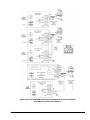
FIG:ELnk_OptiLat
Figure 20: E-Link Gateway to OptiView and Latitude/YCAV/YCIV/YVAA Equipment Connections
(See Table 1 for board cross-reference.)

E-Link Gateway Installation Instructions20
PORT 2
A
RS485
E-Link
+
_
OM SHLD
031-02497-xxx (I/O Board)
331-02496-101
(IPU I Board)
YPAL (ECO2)
1
J4
2
3
4
5
P3+
P3-
GND
+5V
Equipment Cable
BACnet
MS/TP
(38400 baud)
FIG:YPAL
YPAL (ECO2) Setup for MS/TP Bus:
BLUE
WHITE
SHIELD
GRD
+
-
COM SHLD
PORT 2A RS485
WHITE
(Open)
E-Link
BLUE
Figure 21: E-Link Gateway to YPAL (EC02) Equipment Connections
Page is loading ...
Page is loading ...
Page is loading ...
Page is loading ...
Page is loading ...
Page is loading ...
-
 1
1
-
 2
2
-
 3
3
-
 4
4
-
 5
5
-
 6
6
-
 7
7
-
 8
8
-
 9
9
-
 10
10
-
 11
11
-
 12
12
-
 13
13
-
 14
14
-
 15
15
-
 16
16
-
 17
17
-
 18
18
-
 19
19
-
 20
20
-
 21
21
-
 22
22
-
 23
23
-
 24
24
-
 25
25
-
 26
26


Johnson Controls E-Link Installation Instructions Manual
- Type
- Installation Instructions Manual
Ask a question and I''ll find the answer in the document
Finding information in a document is now easier with AI
Related papers
-
Johnson Controls York Smart Equipment SC-EQUIP Installation Instructions Manual
-
-
-
-
-
-
-
-
-
Other documents
-
 Kamstrup RS-485 Installation and User Guide
-
Sinclair SBG-01 User manual
-
York YVAA Variable Speed Drive Screw Chiller User guide
-
Honeywell EXCEL 5000 OPEN ZAPP Installation Instructions Manual
-
-
-
FieldServer EZ Gateway Modbus to BACnet Quick start guide
-
-
Lochinvar Wall Hung 399 Instructions Manual
-
Trane LonWorks TR1 Series VFD Operating instructions
