Carel humiFog direct DLA04UB000 User manual
- Type
- User manual

Integrated Control Solutions & Energy Savings
NO POWER
& SIGNAL
CABLES
TOGETHER
READ CAREFULLY IN THE TEXT!
humiFog direct
User manual


3
ENG
"humiFog direct" +0300073EN rel. 1.2 - 02.05.2019
IMPORTANT WARNINGS:
The humidiers manufactured by CAREL are advanced products, whose
operation is specied in the technical documentation supplied with the
product that can be downloaded, even prior to purchase, from the website
www.carel.com. Every product made by CAREL Industries, in relation to
its advanced level of technology, requires a qualication/ conguration /
setup phase in order to best full your specic application. The lack of such
phase of study, as indicated in the manual, can cause the nal product to
malfunction, of which CAREL cannot be held responsible. The client (builder,
developer or installer of the nal equipment) assumes all responsibility and
risk relating to the conguration of the product in order to achieve the
expected results in relation to the specic nal installation and/or equipping.
In this case, subject to specic agreements, CAREL acts as a consultant for
the success of the installation / start-up / use of the machine, but in no case
does it accept liability for proper operation of the humidier and of the nal
plant, should the warnings and recommendations in this manual or in any
other technical documentation of the product not be followed. In particular,
in addition to the obligation to observe the above mentioned warnings and
recommendations for proper use of the product, we recommend paying
attention to the following warnings:
• DANGER ELECTRIC SHOCK: The humidier includes live electrical
parts. Disconnect the power supply before accessing internal parts, in
case of maintenance and during installation.
• DANGER WATER LEAKS: The humidier automatically and constantly
sucks in/drains quantities of water. Malfunctions in the connections or
humidier may cause leaks.
WARNING:
• Environmental and power supply conditions must conform to the
values specied on the product rating labels.
• Only qualied personnel who are aware of the necessary precautions
and able to perform the required operations correctly may install,
operate or carry out technical service on the product.
• Only water with the characteristics indicated in this manual must be
used.
• All operations on the product must be carried out according to the
instructions provided in this manual. Any uses or modications that are
not authorised by the manufacturer are considered improper. CAREL
Industries declines all liability for any such unauthorised use.
• Do not attempt to open the system in ways other than those described
in this manual.
• Observe the standards in force in the place where the humidier is
installed.
• Keep the humidier out of the reach of children and animals.
• Do not install and use the product near objects that may be damaged
when in contact with water (or condensate). CAREL Industries declines
all liability for direct or indirect damage following water leaks from the
humidier.
• Do not use corrosive chemicals, solvents or aggressive detergents to
clean the inside and outside parts of the humidier, unless specically
indicated in the user manual.
• Do not drop, hit or shake the humidier, as the inside parts and the
linings may be irreparably damaged.
CAREL adopts a continuous development policy. Therefore, CAREL
reserves the right to carry out modications and improvements to any
product described in this document without prior notice. The technical
data in the manual can undergo modications without forewarning. The
liability of CAREL in relation to its own product is governed by CAREL
general contract conditions published on the website www.carel.com
and/or by specic agreements with clients; in particular, within the limits
set by the applicable law, in no way will CAREL, its employees or its branch
oces/aliates be responsible for any lack of earnings or sales, loss of
data and information, cost of replacement goods or services, damage to
objects or persons, work interruptions, or any direct, indirect, accidental,
patrimonial, coverage, punitive, special or consequential damage in any
way caused, be they contractual, out-of-contract, or due to negligence
or other responsibility originating from the installation, use or inability of
use of the product, even if CAREL or its branch oces/aliates have been
warned of the possible damage.
DISPOSAL:
The humidier consists of metal parts and plastic parts. With reference to
the European Parliament and Council Directive 2002/96/EC issued on 27
January 2003 and the related national implementation legislation, please
note that:
1. WEEE cannot be disposed of as municipal waste, said waste must be
collected separately;
2. the public or private waste collection systems dened by local
legislation must be used. Moreover, the equipment can be returned
to the distributor at the end of its working life when buying new
equipment;
3. the equipment may contain hazardous substances: the improper use
or incorrect disposal of such may have negative eects on human
health and on the environment;
4. the symbol (crossed-out wheeley bin) shown on the product or
on the packaging and on the instruction sheet indicates that the
equipment has been introduced onto the market after 13 August
2005 and that it must be disposed of separately;
5. in the event of illegal disposal of electrical and electronic waste, the
penalties are specied by local waste disposal legislation.
Warranty for materials: 2 years (from the manufacture date, excluding
consumables).
Certication: the quality and safety of CAREL products are guaranteed by
CAREL’s ISO 9001 certied design.

4
ENG
"humiFog direct" +0300073EN rel. 1.2 - 02.05.2019

5
ENG
"humiFog direct" +0300073EN rel. 1.2 - 02.05.2019
Contents
1. GENERAL DESCRIPTION AND MODELS 7
1.1 General description ...................................................................................................7
1.2 Operating principle .................................................................................................7
1.3 Cabinet part numbers .............................................................................................. 8
1.4 Hose part numbers ....................................................................................................8
1.5 Blower unit part numbers......................................................................................8
1.6 Main components ......................................................................................................9
1.7 Dimensions and weights.....................................................................................10
1.8 Packaging and shipment ....................................................................................10
1.9 IP rating and standards ......................................................................................... 10
2. CABINET INSTALLATION 11
2.1 Positioning ....................................................................................................................11
2.2 Cabinet water connections ...............................................................................11
2.3 Cabinet electrical installation ...........................................................................12
2.4 Changing the oil cap .............................................................................................13
3. DISTRIBUTION SYSTEM INSTALLATION 13
3.1 Blower unit installation ......................................................................................... 13
3.2 Mounting single blower units on the wall / ceiling ...........................14
3.3 Mounting double blower units on the ceiling ......................................15
3.4 Blower unit electrical connection ..................................................................15
4. ELECTRONIC CONTROLLER SET UP AND
CONNECTIONS 16
4.1 Remote ON/OFF signal connection .............................................................16
4.2 Analogue signal from the main probe and limit probe in .................
the rst zone ...............................................................................................................16
4.3 Analogue signal from the main probe and limit probe in the ........
second zone ................................................................................................................16
4.4 Analogue signal from an external controller ......................................... 17
4.5 Digital signal from humidistat or external controller ......................17
4.6 Serial or Ethernet communication ................................................................ 17
4.7 Alarm relay output ..................................................................................................17
4.8 Unit status digital output ....................................................................................17
4.9 Production percentage analogue outputs ..............................................18
5. STARTUP AND USER INTERFACE 19
5.1 Graphic terminal ....................................................................................................... 19
5.2 Start-up ...........................................................................................................................19
5.3 Touch display .............................................................................................................. 20
5.4 Remote installation of the touch display ..................................................24
6. OPERATION OPTIONS 25
6.1 Main menu and overview of functions ...................................................... 25
6.2 Control ............................................................................................................................26
6.3 Functions ....................................................................................................................... 27
6.4 Congurations ...........................................................................................................28
7. MASTER/SLAVE NETWORK OF HUMIDIFIERS 30
7.1 Description of the Master/Slave system ....................................................30
7.2 Network switch for Master/Slave connection ........................................ 30
7.3 Type of Master/Slave system installation ..................................................30
7.4 Master/Slave system conguration ..............................................................31
8. CONNECTIVITY 33
8.1 Webserver ..................................................................................................................... 33
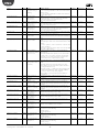
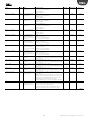
8.2 Supervisor connection .........................................................................................34
8.3 List of Modbus parameters ................................................................................34
8.4 List of BACnet parameters ..................................................................................35
9. WIRELESS PROBES, INSTALLATION AND
CONFIGURATION 36
9.1 Type of installation and wireless probe electrical connections .....36
9.2 Wireless probe installation .................................................................................36
10. ALARM TABLE 37
11. MAINTENANCE 40
11.1 Routine maintenance ............................................................................................ 40
11.2 Special maintenance ............................................................................................40
11.3 Pump maintenance ................................................................................................ 40
11.4 50 hour oil change warning .............................................................................. 41
11.5 Notication, maintenance warning, reset hour counter .................41
11.6 Blower spare parts ...................................................................................................41
11.7 Cabinet spare parts ................................................................................................. 42
12. APPENDIX 43
12.1 Single-zone cabinet wiring diagram ............................................................43
12.2 Two-zone cabinet wiring diagram ................................................................44
12.3 Datasheets .................................................................................................................... 45

6
ENG
"humiFog direct" +0300073EN rel. 1.2 - 02.05.2019

7
ENG
"humiFog direct" +0300073EN rel. 1.2 - 02.05.2019
1. GENERAL DESCRIPTION AND MODELS
1.1 General description
humiFog Direct is a direct humidier for room installation. It consists
of a pumping unit (also called the cabinet) and a distribution system
(comprising blower units) to be installed directly in the room to be
humidied and cooled. The pumping unit is connected to the blower
units by high pressure hoses.
The cabinet is tted with a pump that delivers water at high pressure (70
bars) to the nozzles on the blower units, where it is atomised into very
ne droplets that evaporate spontaneously.
The cabinets are available in the single zone and two-zone version. The
latter can manage two independent zones, reading two separate signals
(from a probe or external controller).
For all models, the minimum ow rate that can be supplied by the pump
is 10% of its nominal ow rate. For this reason, it is recommended to
couple a distribution line that can atomise a ow-rate of water equal at
least to the minimum ow-rate delivered by the pump.
It is important to install the distribution system in a suitable environment
(in terms of volume, air change and operating temperature) so as to
ensure absorption of the atomised water. Carel can provide support for
calculating the required humidication load.
1.2 Operating principle
System operation is based on a request signal from a probe (temperature
or humidity) or external controller. When operation is enabled (remote
on/o ) and at the same time there is a humidication or cooling request
signal, the system opens the ll solenoid valve and activates the pump,
which pumps the water at high pressure (70 bars). After having also
opened the outlet solenoid valve, the initial stage of operation begins,
involving washing and lling the line, after which, when the line is lled
and pressurised, the nozzles will start spraying water.
Modulation is available in PWM mode (pulse width modulation): the
controller alternates a time (set on the display) in which the outlet
solenoid valves are operation, thus atomising the water, with period in
which the outlet valves are closed and the bypass valve is open, thus
interrupting atomisation into the room.
The set point is managed directly by the electronic controller using a
proportional band (P+I) or an oset when reaching the set point.
On reaching the set point, the system stops and enters standby mode,
restarting when there is a new request. For this reason, the system should
be powered on at all times.
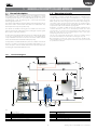
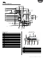
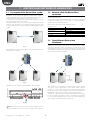
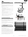
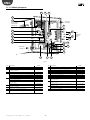
1.2.1 Functional diagram
7 7
5112
6
33
6
8
8
8
10
991 4
12
Fig. 1.a
Key
1 Mains water line
2 Reverse osmosis system
3 Demineralised water line
4 Expansion vessel
5 humiFog Direct cabinet
6 High pressure water hoses (70 bars)
7 humiFog Direct blower units
8 Water drain point
9 On-o ball valve
10 Power supply (230V 50 Hz or 120V 60 Hz)
11
Electrical connection from cabinet to the blowers
12 Mechanical feedwater lter

8
ENG
"humiFog direct" +0300073EN rel. 1.2 - 02.05.2019
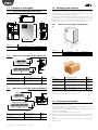
1.3 Cabinet part numbers
Fig. 1.b
The cabinets dier in terms of ow-rate delivered by the pump, power
supply voltage/frequency, and the capacity to control one or two
atomisation racks, managed independently from each other
.
U A _ _ _ D _ _ 0 1
D = 230 V 50 Hz
U = 120 V 60 Hz
1 = single zone
2 = double zone
040 = 40 l/h
080 = 80 l/h
050 = 50 l/h
090 = 90 l/h
Part numbers available:
UA040DD101 40 l/h, 230V 50Hz, single zone
UA040DD201 40 l/h, 230V 50Hz, two zones
UA080DD101 80 l/h, 230V 50Hz, single zone
UA080DD201 80 l/h, 230V 50Hz, two zones
UA050DU101 50 l/h, 120V 60Hz, single zone
UA050DU201 50 l/h, 120V 60Hz, two zones
UA090DU101 90 l/h, 120V 60Hz, single zone
UA090DU201 90 l/h, 120V 60Hz, two zones
Tab. 1.a
N.B. to manage the 230V - 60 Hz power supply a 230V-120V transformer
can be installed upstream and connected to the cabinet. The transformer
must be installed according to safety standards in force.
1.4 Hose part numbers
The high pressure hoses (OD = 10 mm, ID = 6.4 mm) are supplied by
Carel in dierent lengths. The part numbers available are listed below.
All the hoses have with M16x1.5 female couplings with O-rings, ideal for
direct connection to the cabinet and the blower units without needing
to use sealants. Each hose kit includes an M16x1.5 nipple to be used for
coupling dierent hoses together.
Stainless steel pipes can also be used to connect the blowers to the
cabinet. The recommended outside diameter is 10 mm. This solution is
the installer’s responsibility.
Carel recommends using hoses rather than pipes.
UAKT005014 High pressure hose, L = 0.5 m
UAKT010014 High pressure hose, L = 1.0 m
UAKT020014 High pressure hose, L = 2.0 m
UAKT050014 High pressure hose, L = 5.0 m
UAKT100014 High pressure hose, L = 10 m
UAKT200014 High pressure hose, L = 20 m
Tab. 1.b
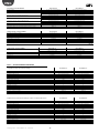
1.5 Blower unit part numbers
Fig. 1.c
The blower units dier based on the number of nozzles, the type of
nozzles (the nozzles are already pre-assembled in the factory), power
supply voltage/frequency and the direction of spray (front or two
directions).
D L A _ _ _ _ _ 0 0
D = 230 V 50 Hz
U = 120 V 60 Hz
Nozzle size:
0 = 1.45 l/h
1 = 2.8 l/h
2 = 4.0 l/h
F = single zone (front)
B = double zone (front/back)
Number of nozzle
Part numbers available:
P/N 230 V 50 Hz BLOWERS (CE)
DLA02DF000 Front blower 3.0 l/h (2 x 1.45 l/h nozzles) 230 V 50 Hz
DLA02DF100 Front blower 5.0 l/h (2 x 2.8 l/h nozzles) 230 V 50 Hz
DLA02DF200 Front blower 8.0 l/h (2 x 4.0 l/h nozzles) 230 V 50 Hz
DLA04DF000 Front blower 6.0 l/h (4 x 1.45 l/h nozzles) 230 V 50 Hz
DLA04DF100 Front blower 11.0 l/h (4 x 2.8 l/h nozzles) 230 V 50 Hz
DLA04DF200 Front blower 16.0 l/h (4 x 4.0 l/h nozzles) 230 V 50 Hz
DLA04DB000 Double blower 6.0 l/h (4 x 1.45 l/h nozzles) 230 V 50 Hz
DLA04DB100 Double blower 11.0 l/h (4 x 2.8 l/h nozzles) 230 V 50 Hz
DLA04DB200 Double blower 16.0 l/h (4 x 4.0 l/h nozzles) 230 V 50 Hz
DLA08DB000 Double blower 12.0 l/h (8 x 1.45 l/h nozzles) 230 V 50 Hz
DLA08DB100 Double blower 22.0 l/h (8 x 2.8 l/h nozzles) 230 V 50 Hz
DLA08DB200 Double blower 32.0 l/h (8 x 4.0 l/h nozzles) 230 V 50 Hz
Tab. 1.c
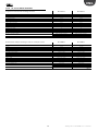
P/N 120 V 60 Hz BLOWERS
DLA02UF000 Front blower 3.0 l/h (2 1x .45 l/h nozzles) 120 V 60 Hz
DLA02UF100 Front blower 5.0 l/h (2 x 2.8 l/h nozzles) 120 V 60 Hz
DLA02UF200 Front blower 8.0 l/h (2x 4.0 l/h nozzles) 120 V 60 Hz
DLA04UF000 Front blower 6.0 l/h (4 x 1.45 l/h nozzles) 120 V 60 Hz
DLA04UF100 Front blower 11.0 l/h (4 x 2.8 l/h nozzles) 120 V 60 Hz
DLA04UF200 Front blower 16.0 l/h (4 x nozzles from 4.0l/h) 120 V 60 Hz
DLA04UB000 Double blower 6.0 l/h (4 x 1.45 l/h nozzles) 120 V 60 Hz
DLA04UB100 Double blower 11.0 l/h (4 x 2.8 l/h nozzles) 120 V 60 Hz
DLA04UB200 Double blower 16.0 l/h (4 x 4.0 l/h nozzles) 120 V 60 Hz
DLA08UB000 Double blower 12.0 l/h (8 x 1.45 l/h nozzles) 120 V 60 Hz
DLA08UB100 Double blower 22.0 l/h (8 x 2.8 l/h nozzles) 120 V 60 Hz
DLA08UB200 Double blower 32.0 l/h (8 x 4.0 l/h nozzles) 120 V 60 Hz
Tab. 1.d

9
ENG
"humiFog direct" +0300073EN rel. 1.2 - 02.05.2019
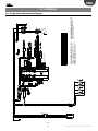
1.6 Main components
3
16
15
15
16
14
10
18
21
22
87
5
1
4
2
1
water inlet
3/4” GAS F
ow
and return
M16x1.5
male
6
water drain
3/4" GAS F
power supply
230 V 50 Hz
120 V 60 Hz
2
19
21
23
20
9
17
1312
11
Fig. 1.d
Cabinet water circuit
Ref. Description
1 Water inlet lter
2 Pressure reducer
3 NC ll solenoid valve
4 Low pressure gauge
5 Motor
6 Pump
7 High pressure gauge
8 High pressure sensor
9 Temperature-controlled safety valve
10 High pressure sensor
11 Temperature sensor
12 Overow valve
13 Drain solenoid valve
14 Bypass solenoid valve
15 NC ll solenoid valve
16 NO return solenoid valve
17 Fuse kit
18 pGDx display
19 Controller
20 Expansion card
21 Transformer
22 SSR
23 Cooling fan
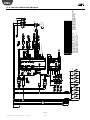
6 5 4 3 2
8
7
1
input / output water
Single-blower: M16 x 1.5 male
Double blower: M16 x 1.5 female
Fig. 1.e
Ref. Description
1 metal support / wall bracket
2 side plastic cover
3 centre plastic cover
4 pressurised water manifold
5 nozzle
6 power LED
7 terminal block for blower power supply
8 fan

10
ENG
"humiFog direct" +0300073EN rel. 1.2 - 02.05.2019
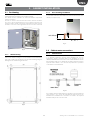
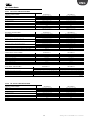
1.7 Dimensions and weights
1.7.1 Dimensions and weights of the cabinet
630
800
805
347
100
60
M16x1.5M
M16x1.5M
M16x1.5M
M16x1.5M
60 60
310
235
75
98,5
80
50
50 50
5050
60,5
93
3/4"G f
3/4"G f
Fig. 1.f
Dimensions Weight
630x300x800 mm
(24.8"x11.8"x31.5")
UA040-UA050 UA080-UA090
single zone two zones single zone two zones
60 kg (132 lb) 64 kg (141 lb) 64 kg (141 lb) 68 kg (149 lb)
Tab. 1.e
1.7.2 Dimensions and weights of the single blowers
640
940
200
200
180
17,5
19
IN/OUT
M16X1,5
Fig. 1.g
P/N Dimensions [a x b x c] Weight
DLA02xFx00
Single blower, 2 modules
640 x 200 x 180 mm
(25 x 8 x 7 inches)
4.5 kg
(9 lb)
DLA04xFx00
Single blower, 4 modules
940 x 200 x 180 mm
(37 x 8 x 7 inches)
5.6 kg
(12 lb)
Tab. 1.f
1.7.3 Dimensions and weights of the double blowers
940
200
225
640
200
400
IN/OUT
M16X1,5
Fig. 1.h
P/N Dimensions [a x b x c] Weight
DLA04xBx00
Double blower, 2 modules
640 x 200 x 400 mm
(25 x 8 x 16 inches)
9.2 kg
(20 lb)
DLA08xBx00
Double blower, 4 modules
940 x 200 x 400 mm
(37 x 8 x 16 inches)
15.5 kg
(34 lb)
Tab. 1.g
1.8 Packaging and shipment
The cabinet is packaged and delivered on a wooden pallet with a
cardboard cover. The user is responsible for moving the cabinet near the
point of operation, removing the packaging and placing it in a position
ready for the water and electrical connections.
The blowers are delivered already assembled in cardboard boxes. The user
is responsible for removing the blower from the packaging, removing the
side plastic covers so as to make the water and electrical connections,
and then replacing the plastic covers before starting the system.
1.8.1 Dimensions and weights of the packages
Fig. 1.i
Dimensions Weight
720x460x1020 mm
(28.5"x18"x40")
UA040-UA050 UA080-UA090
single zone two zones single zone two zones
64 kg (141 lb) 68 kg (149 lb) 68 kg (149 lb) 72 kg (158 lb)
Tab. 1.h
Fig. 1.j
P/N Dimensions [L x W x H] Weight
DLA02xFx00
front blower 2 mod
755 x 235 x 295 mm
(30 x 9 x 12 inches)
5.7 kg
(12 lb)
DLA04xFx00
front blower 4 mod
1050 x 235 x 295 mm
(41 x 9 x 12 inches)
7.4 kg
(16 lb)
DLA04xBx00
double blower 2 mod
755 x 470 x 295 mm
(30 x 18 x 12 inches)
11.4 kg
(25 lb)
DLA08xBx00
double blower 4 mod
1050 x 470 x 295 mm
(41 x 18 x 12 inches)
18 kg
(39 lb)
Delivery and storage temperature must be between -10°C - 50°C and
humidity between 0% - 90% non-condensing.
1.9 IP rating and standards
The IP rating of the cabinet is IP20.
The IP rating of the blowers is IP20.
The IP rating of the blowers is not a problem for installation, as all the
components inside have a higher IP rating.
The blowers can in fact be installed in rooms with very high humidity (up
to 95% non-condensing).
The unit is compliant with the Machinery Directive.
The unit is CE marked in the 230 Vac 50 Hz version in accordance with IEC
60335-1, IEC 60335-2, EN 60335, EN 61000-6-2 (2006) and EN 61000-6-4
(2007).
The unit is UL marked in the 120 Vac 60 Hz version in accordance with
directive UL998.

11
ENG
"humiFog direct" +0300073EN rel. 1.2 - 02.05.2019
2. CABINET INSTALLATION
2.1 Positioning
The cabinet, being IP20, must be installed in a closed compartment,
sheltered from the rain, water spray and direct sunlight.
The cabinet must be installed in an environment with a temperature
between 5 and 40°C.
Around 1 m clearance must be left in front of the cabinet to allow the
door to be opened and maintenance to be performed. Around 0.5 m
clearance needs to be left on both sides of the cabinet to allow space for
the water connections on the right and electrical connections on the left.
Fig. 2.a
2.1.1 Wall mounting
The cabinets can be wall-mounted or oor-standing.
In the event of wall mounting, it is recommended to use the metal frames
and screws supplied. See the distances shown in the following image for
drilling the holes and fastening the brackets.
Fig. 2.b
2.1.2 Floor-standing installation
For oor-standing installation, the unit needs to rest on a raised platform
so as to allow connection of the drain hose, located on the bottom of the
cabinet (see chapter 2.2.3).
min 30 cm
Fig. 2.c
2.2 Cabinet water connections
2.2.1 Feedwater line
An expansion vessel should always be installed upstream of the cabinet,
so as attenuate variations in pressure in the feedwater line. It is also
suggested to install a mechanical lter on the feedwater line to the
cabinet (P/N ECKVESS050 for the lter vessel and P/N ECKFILT050 for the
lter cartridge). Finally, an on-o ball valve should be installed on the line
upstream of the cabinet, so as to allow for any maintenance operations
on the water circuit downstream.
Fig. 2.d
A hose with a minimum diameter Ø=1/2” should be connected upstream
of the cabinet so as to ensure the right ow-rate and pressure to the
humidier. The humidier inlet connection is 3/4” GAS F. The required
humidier inlet pressure is at least 3 bars.

12
ENG
"humiFog direct" +0300073EN rel. 1.2 - 02.05.2019
2.2.2 Feedwater characteristics
humiFog Direct requires demineralised water, so as to ensure:
• minimum maintenance;
• no blockages of the nozzles;
• no dust (the droplets that evaporate will not leave mineral salts in the
environment);
• improved hygiene.
The use of demineralised water is also required to comply with standards
UNI8883, VDI6022 and VDI3803.
humiFog Direct must only operate on demineralised water that falls
within the limits listed in the following table. Normally, these values can
be obtained by reverse osmosis or nanoltration of the feedwater.
Specic conductivity 25 - 80 µS/cm
pH 5.5 – 8.5
Total hardness (TH) 0 - 25 mg/l CaCO3
Temporary hardness 0 - 15 mg/l CaCO3
Chlorides (Cl) 0 - 10 ppm Cl
Iron + manganese (Fe + Mn) 0 mg/l
Silicon dioxide (SiO2) 0 - 1 mg/l
Chlorine ions (Cl-) 0 mg/l
Calcium sulphate (CaSO4) 0 - 5 mg/l
2.2.3 Cabinet drain connection
The drain point located at the bottom of the cabinet must be connected
externally (3/4" GAS F tting) to an open discharge with drain trap.
235
93
3/4"G f
Fig. 2.e
Also remember that the cabinet cannot be installed on the oor without
a support that keeps the cabinet raised by at least 20-30 cm.
2.2.4 Blower water supply line
With reference to the high-pressure hoses provided by CAREL (inside
diameter Ø = 6.3 mm), in order to ensure correct operation of the
atomisation system, the water supply line to the blowers in a single zone
must respect the following maximum lengths:
Model Rated pump
capacity [L/h]
Maximum hose length supplying
the blowers* [m]
UA040DD2** 40
25
UA050DU2** 50
UA040DD1** 40
50
UA050DU1** 50
UA080DD2** 80
50
UA090DU2** 90
UA080DD1** 80
100
UA090DU1** 90
Tab. 2.a
* The values shown refer to the water circuit in a single zone and the last
blower on the line.
Contact CAREL for longer water lines.
2.3 Cabinet electrical installation
The cabinet must be connected to the mains by the user.
230 V 50 Hz for cabinet CE version UA***DD*01
120 V 60 Hz for cabinet UL version UA***DD*01
The connection must be compliant with local standards, using a suitably-
sized cable. A three-wire cable (line + neutral + earth/ground) must be
connected to the three terminals (L + N + GR).
Fig. 2.f
Cabinet terminal Power cable
L L / F (line)
N N / W (neutral)
GR GR / PE (earth)
Important: t an external power switch on the humidier power supply
line to isolate the power supply, and a TT earthing system with earth fault
current of 30 mA.
No additional wiring is required to the cabinet terminal block, except
for the power supply to the blower fans, using the terminals. For the
electrical connections from the cabinet to the blowers, see chapter 3.4.
Fig. 2.g
2.3.1 Fuses
The following table lists the technical specications of the fuses supplied
for the dierent cabinets:
UA0*0DD*** (50 Hz)
Fuse Single-zone cabinet Two-zone cabinet
F1 1 A (upstream of the transformer) 1 A (upstream of the transformer)
F2 1 A (upstream of the transformer) 1 A (upstream of the transformer)
F3 4 A (downstream of the transf.) 1 A (upstream of the transformer)
F4 1 A (upstream of the transformer)
F5 4 A (downstream of the transf.)
F6 4 A (downstream of the transf.)
Tab. 2.b
UA0*0DU*** (60 Hz)
Fuse Single-zone cabinet Two-zone cabinet
F1 2.5A (upstream of the transformer) 2.5A (upstream of the trans-
former)
F2 2.5A (upstream of the transformer) 2.5A (upstream of the transf.)
F3 4 A (downstream of the transf.) 2.5A (upstream of the transf.)
F4 2.5A (upstream of the transf.)
F5 4 A (downstream of the transf.)
F6 4 A (downstream of the transf.)
Tab. 2.c
Fuses F1, F2, F3*, F4* are installed in the fuse carriers (Fig. 2.h).
Fuses F3, F5*, F6* are installed on the top surface of the corresponding
transformers (components no. 17 in Fig. 1.d).
* indicates the P/N for the fuse on the two-zone cabinet.

13
ENG
"humiFog direct" +0300073EN rel. 1.2 - 02.05.2019
3. DISTRIBUTION SYSTEM INSTALLATION
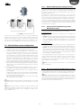
3.1 Blower unit installation
The humiFog Direct system works by connecting the cabinet to a
number of blower units installed directly in the room to be humidied
and/or cooled.
The following simple rules must be kept in mind when installing the
blower units:
• the minimum ow-rate that can be atomised in the room is 8 l/h
(irrespective of the size of the pump). The minimum number of blower
units must therefore be dened based on the number and size of the
chosen nozzles.
The maximum numbers of blower units that can be connected to a
cabinet are:
• 12 blower units with 2 nozzles
• 6 blower units with 4 nozzles
• 3 blower units with 8 nozzles
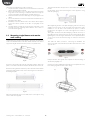
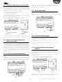
The blower units must be suitably positioned so as to allow complete
absorption of the sprayed water. Consequently it is recommended to
install the blowers a due distance apart, at a sucient height from the
oor and with free space at the front without obstacles.
The blower units can be mounted either on the wall or on the ceiling.
For a correct installation, see the example in Fig. 3.a or contact Carel for
dierent temperature and humidity conditions.
Fig. 2.h
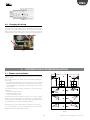
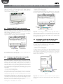
2.4 Changing the oil cap
During installation, before starting the unit, remember to replace the red
oil cap (A) on the pump with the yellow one (B) supplied. The red cap is
closed and is only used for transport. The yellow cap has a vent opening
and is used for normal operation of the system. The yellow cap is supplied
inside the cabinet, tied to the high pressure gauge (see the image below).
A
B
Fig. 2.i
0.5 ÷ 1m
≥ 5m
light light
≥ 5m
≥ 4m
≤ 4m
SI
rH = 40% T = 25 °C
SI NO
SI NO
SI NO
NO
≤ 10°
≤ 10°
Fig. 3.a

14
ENG
"humiFog direct" +0300073EN rel. 1.2 - 02.05.2019
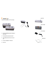
The blower unit installation procedure is as follows:
1. Unpack the blower unit from the box it was delivered in. The blower
units are delivered fully assembled.
2. Remove the side plastic covers cover from the blower. Unscrew the
long screws on the side using a screwdriver. Make sure to keep the
screws, as they will be needed again for assembly at the end.
3. Mount the blower unit on the metal support. See paragraph 3.2 for
details.
4. Connect the water line to the inlet on the blower units (M16x1.5). See
paragraph 3.3 for details.
5. Electrically connect the blower units to the cabinet, which supplies
power and controls operation of the fans. See paragraph 3.4 for
details.
6. Complete blower assembly by repositioning the side plastic covers
removed previously, and xing them with the same screws as
removed at the beginning.
3.2 Mounting single blower units on the
wall / ceiling
The single blower units (P/N DLA%F) are designed to be installed on a
vertical wall using a special metal support to be xed to the wall using
screws. Check that the wall is made from suitable material and is able to
support the weight of the blower unit (concrete, not plasterboard).
Fig. 3.b
First remove the blower unit from the packaging and take o the side
plastic covers. Remove the blower unit from the steel bracket on the rear.
Rest the bracket against the wall in the position where the blower will be
installed, and then drill four holes in the wall, using the steel bracket as
the drilling template.
Fig. 3.c
Fig. 3.d
After having drilled the holes in the wall, x the metal support using
anchor screws (not supplied).
Then attach the blower to the protrusions on the wall-mounting support
bracket.
Fix the blower unit to the bracket using the screws supplied in a bag
inside the packaging.
Fig. 3.e
When tightening the rst screw (M6 self-tapping in Ø=5.5 mm holes),
slightly loosen the screws on the ring clamps that support the nozzle
manifold, so as to be able to turn it and free up space to continue
mounting the unit. Tighten one screw on the right and one screw on
the left.
Then tighten the third screw (M4 self-tapping in Ø=3.5 mm hole) on
the right-hand side of the blower (opposite the terminal block). When
tightening this screw, the angle of the blower can be adjusted between
-10°/-5°/0°/+5°/+10° from horizontal, using one of the ve small holes
provided.
Then make the water connections, connecting the feedwater line
either on the right or left of the blower, and the water return line on the
opposite side.
Fig. 3.f
Finally, t the two cable glands and complete the electrical wiring, as
described in paragraph 3.4.
Carel also provides an additional kit (including a special plate bent at 90°)
for mounting single blower units on the ceiling.
Fig. 3.g

15
ENG
"humiFog direct" +0300073EN rel. 1.2 - 02.05.2019
3.3 Mounting double blower units on the
ceiling
The double blower units (P/N DLA%B) are designed to be installed on
the ceiling by anchoring them to a metal support that can support their
weight and the vibrations due to the pressurised water. To mount the
blower unit, use the special attachments provided on the unit’s metal
structure.
Carel provides additional kits with everything needed to complete
installation easily. Make sure to carefully choose the point where the
vertical support bar will be anchored. The support bar must not be longer
than 1 metre, so as to avoid excessive bending and vibrations.
Fig. 3.h
After installing the blower, make the water connections by connecting
the feedwater and return lines to the two pipes provided on the top of
the blower. The feedwater/return lines can be connected either to the
right or left.
Fig. 3.i
Finally, t the two cable glands and complete the electrical wiring, as
described in paragraph 3.4.
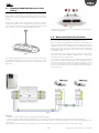
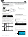
3.4 Blower unit electrical connection
The blower units must be electrically connected to the cabinet so that
they are activated only when there is a humidication request
Before electrically connecting the blower units to the cabinet, make sure
that the cable glands supplied with the cabinet and the blower units are
available. All connections to be made by the user (cabinet power supply,
blower unit power supply, probe connections, etc.) must be performed
by running the cables through the cable glands, and in accordance with
local safety standards.
Also check that the cable is the right size for the distance and voltages
used. Carel recommends an AWG14 or AWG12 cable, as shown in the
technical data at the end of the manual.
To connect power to the blower units, connect three suitably-sized wires
(line + neutral + earth) from the terminals on the cabinet (shown in the
gure) to the terminals on the blower (shown in the gure). To power
a second and subsequent blowers, start from the free terminals on of
the previous blower and connect to the terminals on the next blower, as
shown in the gure.
Fig. 3.j
Important:
• remember to run the wires through the cable glands (marked in the gure).
• check the maximum number of blower units that can be connected to each cabinet in the tables in Appendix 12 at the end of the manual.
• when connecting the line (L) and neutral (N) from the cabinet to the blower units, never reverse L and N. Reversing or crossing over the wiring may cause
short-circuits.
After having completed the wiring, close the side plastic covers again and x them using the screws. The system is now ready to operate.

16
ENG
"humiFog direct" +0300073EN rel. 1.2 - 02.05.2019
4. ELECTRONIC CONTROLLER SET UP AND CONNECTIONS
After having correctly installed the cabinet and completed the water and
electrical connections, connect the signals used to interface with the
humiFog Direct humidier to the c.pHC electronic controller (and the
c.pCO controller on two-zone cabinets.
Fig. 4.a
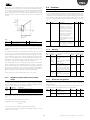
4.1 Remote ON/OFF signal connection
The remote ON/OFF contact is used to enable operation from an external
device. It is a digital contact that can be either open or closed: when the
terminal is open, humiFog cannot operate. The contact refers to inputs 7
[GND]- 8 [digit] on terminal M2 on the c.pHC.
The remote ON/OFF contact must not be confused with the ON/OFF
signal that manages operation, described in paragraph 4.5.
Fig. 4.b
If not intending to use an external contact to start / stop the unit, leave
the terminal short-circuited (as supplied).
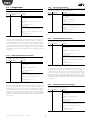
4.2 Analogue signal from the main probe
and limit probe in the first zone
humiFog Direct can be controlled using an analogue signal (modulating)
from a main humidity or temperature probe connected to the c.pHC
electronic controller. If connected to a humidity probe, humiFog Direct
will display the relative humidity read by the probe. If connected to a
temperature probe, on the other hand, humiFog Direct will display the
temperature. Based on the probe reading and the deviation from the set
point, humiFog Direct will modulate the humidication load according
to the PWM principle (see paragraph 6.2). The following types of probes
are allowed:
• 4-20 mA, 0-20 mA current probes
• 0-10 V, 0-1 V, 2-10 V voltage probes
The analogue signal from the main probe in the rst zone is connected to
the c.pHC controller via inputs 1 [IN a] 2 [GND] 3 [+12 Vdc] on terminal M2.
The limit probe (optional) is used for the auxiliary function to reduce
humiFog Direct humidication or cooling capacity when approaching
a set humidity or temperature threshold (on the display or external
controller). To set the threshold, select operation with limit probe on the
display. The threshold will either be a humidity or temperature value. The
limit probe can also be used without using a main probe.
The following types of probes are allowed:
• 4-20 mA, 0-20 mA current probes
• 0-10 V, 0-1 V, 2-10 V voltage probes
The analogue signal from the limit probe in the rst zone is connected to
the c.pHC controller via inputs 5 [IN a] 6 [GND] 3 [+12 Vdc] on terminal M2.
Fig. 4.c
Important: if connecting a probe with voltage signal that requires a
power supply greater than the +12 Vdc supplied to the terminal on the
c.pHC, the third wire must not be connected to input 3 [+12 Vdc] but
rather to terminal GA1 [+24 Vac], made available on the cabinet terminal
block, right above the c.pHC.
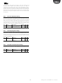
4.3 Analogue signal from the main probe
and limit probe in the second zone
If a second zone is used (only with UA%DD201 and UA%DU201 cabinets),
the main probe corresponding to the second zone must be connected to
the c.pCOe expansion installed under the c.pHC controller.
The following types of probes are allowed:
• 4-20 mA, 0-20 mA current probes
• 0-10 V, 0-1 V, 2-10 V voltage probes
The inputs used for the main probe are U1 [IN a] and [GND] on terminal
J2, and the power supply is taken from the +Vdc on terminal J9. The limit
probe (optional) corresponding to the second zone is connected to
inputs U2 [IN a] and [GND] on terminal J2, and the power supply is taken
from the +Vdc on terminal J9.
Fig. 4.d
Important: unlike the rst zone, the connection to the c.pCOe expansion
relating to the second zone can supply power to probes that require up
to 21 Vdc.
7 [GND]8 [digit]
REMOTE ONOFF
[IN a] [GND] [+15 Vdc] [IN a] [GND] [+15 Vdc]
MAIN PROBE
ZONE 1
LIMIT PROBE
ZONE 1
[IN a] [GND] [+15 Vdc] [IN a] [GND] [+15 Vdc]
MAIN PROBE
ZONE 1
LIMIT PROBE
ZONE 1

17
ENG
"humiFog direct" +0300073EN rel. 1.2 - 02.05.2019
4.4 Analogue signal from an ext. controller
As an alternative to the main probe, a signal from an external controller
can be used. The latter processes the request to send to humiFog Direct
via an analogue signal, which varies from 0 to 100%. humiFog will adjust
the capacity delivered proportionally to the signal received, and the
display will show the request sent as a percentage.
The following types of proportional signals are allowed:
• 4-20 mA, 0-20 mA current signals
• 0-10 V, 0-1 V, 2-10 V voltage signals
The external signal for the rst zone is connected to the c.pHC controller
via inputs 1 [IN a] and 2 [GND] on terminal M2.
The external signal for the second zone is connected to the c.pCOe
controller via inputs U1 [IN a] and [GND] on the terminal J2.
Fig. 4.e Fig. 4.f
The limit probes can also be associated with the external proportional
signal, and will be connected as shown in the previous paragraphs.
4.5 Digital signal from humidistat or
external controller
The signal from the external controller can be replaced by the signal from
a humidistat, thermostat, or any external device with digital contact. In
this case, humiFog Direct will work in ON/OFF mode, either delivering
100% of ow-rate or remaining in standby. The capacity delivered can be
reduced by setting parameter P0 (the reduction is managed by PWM, see
paragraph 6.5). The electrical connection is the same as in the previous
case shown in Figure 4.e. Make sure to congure the humiFog Direct (via
the screens on the display) so that it can be controlled by an ON/OFF
signal from external controller or device.
4.6 Serial or Ethernet communication
humiFog Direct can be controlled by a supervisor that reads the humiFog
Direct parameters and sends commands. To connect a supervisor, the
RS485 serial port (terminal M12, inputs 1 [Tx/Rx-] 2 [Tx/Rx+] 3 [GND]) or
Ethernet port is used. The choice of which port to use depends on the
supervisor. Modbus and BACnet communication protocols are available
as standard: no auxiliary cards need to be tted on the c.pHC controller
Fig. 4.g
The Ethernet port can also be used for the Webserver function (see
Chapter 8), so as to monitor and control humiFog Direct via a local
network, without needing a supervisor.
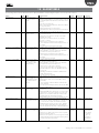
4.7 Alarm relay output
The digital output for communication of an alarm status is connected to
contacts 1-2-3 on terminal M6 on the c.pHC. N.C. logic is set by connecting
the two wires to contacts 1-2, while N.O. logic is set connecting the two
wires to contacts 1-3.
Fig. 4.h
4.8 Unit status digital output
The c.pHC controller provides a digital output corresponding to unit status.
This is a voltage-free contact that provides the following information:
• contact closed: unit on or in standby
• contact open: unit o (OFF from keypad or from remote contact, or
no power)
The unit status digital output is available at contacts 1-2 on terminal M5
on the c.pHC.
4.9 Production percentage analogue
outputs
The c.pHC controller provides an analogue output (0-10 V) corresponding
to the percentage of production that humiFog Direct is delivering.
The output replicates the request signal relating to the corresponding
humiFog Direct zone.
The production percentage analogue outputs are connected to the
following terminals:
• zone 1: outputs 1 and 2 on terminal M8 on the c.pHC.
• zone 2: outputs U3 and GND on terminal J2 on the c.pCOe.
Fig. 4.i Fig. 4.j
Important: when several GND contacts are wired to the same terminal
these are equivalent to each other, and can be used indierently.
[IN a] [GND] [IN a] [GND]
EXTERNAL SIGNAL ZONE 1
EXTERNAL
SIGNAL ZONE 2
1 [Tx/Rx-]
2 [Tx/Rx+]
3 [GND]
SERIAL RS485
ETHERNET
N.C.
N.O.
ALARM RELAY
% PRODUCTION
ZONE 1
SYSTEM
STATUS
% PRODUCTION
ZONE 2

18
ENG
"humiFog direct" +0300073EN rel. 1.2 - 02.05.2019
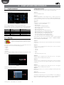
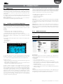
5. STARTUP AND USER INTERFACE
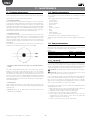
5.1 Graphic terminal
The 4.3” touch graphic terminal has an interface with coloured and
animated icons. The contents of the display can be scrolled up and down
simply and intuitively.
Fig. 5.a
On the right of the graphic terminal is the notication bar.
If the humidier is powered on, the notication bar is always on, even when
the display is o, and provides immediate information on humidier status.
Bar colour Bar status Humidier status
White Light on steady Unit o (o or standby)
Green Light on steady Unit in production, start-up, ll
Blue Light on steady Washing in progress
Red Light ashing Alarm on the unit
Cyan Light on steady Unit in manual mode
Yellow Light ashing Unit shutting down
Tab. 5.a
5.2 Start-up
Switch on humiFog Direct by moving the disconnect
switch on the front panel from position O to position
I.
The display shows the “humiFog Direct” logo, after which the menu
language can be chosen, from the following options:
• English
• Italiano
• Deutsch
• Français
• Español
Tap the language and ag icon with your nger to access the drop-down
menu with the options.
Fig. 5.b
Scroll the menu with your nger.
Select the desired language and then conrm.
Fig. 5.c
Configuration wizard
When starting the rst time, a wizard is provided to quickly set the main
unit parameters. There are at most 10 steps to set up the unit:
Step 1/10
Enter the humidier model.
Step 2/10
Enter the humidication load in kg/h for zone 1 and, if present, zone
2. The humidication load can be easily calculated by multiplying the
number of atomising nozzles in the zone by the ow-rate delivered by
each nozzle.
Step 3/10
Select zone 1 control mode from the options:
• ON/OFF contact (e.g. humidistat);
• External signal:
• External signal + humidity limit probe;
• External signal + temperature limit probe;
• Main humidity probe;
• Main temperature probe;
• Main humidity probe + humidity limit probe;
• Main temperature probe + temperature limit probe;
• Main humidity probe + temperature limit probe;
• Main temperature probe + humidity limit probe;
• Two main humidity probes (weighted average);
• Two main temperature probes (weighted average);
If using wireless probes, select the parameter that is shown by default
and at the end of the wizard refer to chapter “9. WIRELESS PROBES;
INSTALLATION AND CONFIGURATION”.
Step 4/10
Select zone 2 control mode. The options available are those already listed
in step 3/10.
Step 5/10
Select the type of signal from the main probe or from an external
controller to control zone 1:
• 0-10 V;
• 4-20 mA;
• 0-20 mA;
• 0-1 V;
• 2-10 V;
• NTC (temperature probe only)
Step 6/10
Select the type of signal from the limit probe in zone 1. The signals
available are those already listed in step 5/10.
Step 7/10
Select the type of signal from the main probe or from an external
controller to control zone 2. The signals available are those already listed
in step 5/10.
Step 8/10
Select the type of signal from the limit probe in zone 2. The signals
available are those already listed in step 5/10.
Step 9/10
Enter the set points for zone 1 and zone 2 relating to the main probe and
limit probe.
Step 10/10
Enter the system date and time.
The wizard is now nished: you can choose whether or not to display it
the next time humiFog direct is powered on. In any case, the wizard is
always accessible from the settings menu on the graphic terminal.

19
ENG
"humiFog direct" +0300073EN rel. 1.2 - 02.05.2019
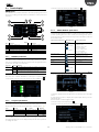
5.3 Touch display
HOME menu
The “HOME” menu includes information about the pumping station and
the zones, including current production, information on the probes and
unit status.
11
1
2
4
5
3
6
7
8 9
10
Fig. 5.d
Pos. Function Pos. Function
1 ON/OFF quick menu 7 Notication centre
2 Set point quick menu 8 System date & time
3 Input/output quick menu 9 Scheduler status
4 System information quick menu 10 Master/Slave Network
5 Descriptive icon of zone status 11 Main menu
6 Alarm list
Tab. 5.b
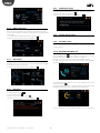
5.3.1 ON/OFF quick menu
Pressing the ON/OFF quick menu icon accesses the screen for switching
the entire system or individual zones on and o. To switch on or o the
unit or zones (ON when the indicator is positioned to the right, OFF when
positioned to the left), press the button.
Message Values Meaning
Unit ON Enables the pump to operate according to zone request
OFF Switches the pumping unit OFF
Zone 1/2
(visible only
if unit ON)
START Enables atomisation in zone 1/2 according to the request
PAUSE Temporarily stop atomisation in zone 1/2
Tab. 5.a
The menu also contains information on the type of system start-up
control signal. To return to the home menu, press the “HOME” icon
Fig. 5.e
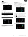
5.3.2 Set point quick menu
Press the icon to access the menu. The menu is used to modify the set
point and proportional control band. Press the white number to change
the value. Enter the desired value and press the conrm button (
).
Title Message Values Default
Zone 1 set
(Zone 2 set)
Main probe set point 0-100% rH 0-40 °C 50% rH 25 °C
Main probe band 0-10% rH 0-10 °C 5% rH 2 °C
Limit probe set point 0-100% rH 0-40 °C 80% rH 15 °C
Limit probe band 0-10% rH 0-10 °C 5% rH 2 °C
Tab. 5.c
To move from one area to another, or from one page to another, press
the right and left arrows on the display and repeat the same operations
to change the values.
To return to the home menu, press the “HOME” icon
Fig. 5.f
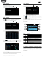
5.3.3 INPUT/OUTPUT quick menu
Press the icon to access the menu.
The input/output dashboard oers an intuitive and real-time view of the
system operating status, the values read by the humiFog direct cabinet
probes, the status of the mechanical components in the water circuit and
the water ow path.
Mechanical component I/O dashboard
symbol
System components
Solenoid valve
(Valve closed)
(Valve open)
FV: cabinet ll valve
BYP: bypass valve
DC: cabinet drain valve
FV1: zone 1 ll valve
DR1: zone 1 drain valve
FV2: zone 2 ll valve
DR2: zone 2 drain valve
Pressure sensor
LPS: low pressure sensor
RHP: high pressure sensor
Temperature sensor
T: water temperature sensor
Pressure switch
HP: high pressure switch
Pump
Cabinet pump
Nozzles
(Atomise ON
(Atomise OFF)
Zone nozzles
Tab. 5.d
To return to the home menu, press the “HOME” icon
Fig. 5.g
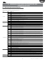
To switch to display the input/output values in table form, press the right
arrow.
If using wireless probes, to display the input/output values, press the
right arrow again.
Use the slider to scroll through the table.
To return to the previous display, press
To return to the home menu, press the “HOME” icon
Fig. 5.h

20
ENG
"humiFog direct" +0300073EN rel. 1.2 - 02.05.2019
Fig. 5.i
5.3.4 INFO quick menu
Press the icon to access the menu.
Menu describing humidier status, software and hardware information.
To move from one page to another, press the arrows on the right and left
of the display.
To scroll through the displayed information, press the slider.
To return to the home menu, press the “HOME” icon
Fig. 5.j
5.3.5 Zone status
To view more details for the single zone, on the display home page press
the white nozzle icon or use the arrows on the right and left of the display
to move from one zone to the other.
To return to the home menu, press the “HOME” icon
Fig. 5.k
5.3.6 Alarm list
Press the icon to display the alarm list.
To view the alarm log, press
To reset the alarms, press
To return to the previous display, press
To return to the home menu, press the “HOME” icon
Fig. 5.l
5.3.7 Notification centre
Press the icon to access the notication centre.
To view the details of an individual notication, press the notication.
To return to the previous display, press
To return to the home menu, press the “HOME” icon
Fig. 5.m
5.3.8 System date and time
The system date and time is displayed.
5.3.9 Scheduler status
If enabled, the scheduler status (on/o ) is shown. Pressing the icon
accesses the scheduler section, described in the following paragraph
“5.3.16 Scheduler”.
5.3.10 MASTER/SLAVE Network
Only for single-zone cabinets, if the master/slave network is enabled for
several humidiers, the
icon is displayed. For the master unit, the
letter M is displayed, for slave units the letter S is displayed.
Press the icon to access information from the humidier network.
The page displayed shows some of the characteristics of the individual
unit and the system.
Fig. 5.n
To quickly display the IP addresses of the units making up the master/
slave network, press
.
To view the page with details on current production and the status of the
humidiers in the master/slave network, press the right arrow.
Fig. 5.o
To access information on the individual humidier, press the desired unit.
Page is loading ...
Page is loading ...
Page is loading ...
Page is loading ...
Page is loading ...
Page is loading ...
Page is loading ...
Page is loading ...
Page is loading ...
Page is loading ...
Page is loading ...
Page is loading ...
Page is loading ...
Page is loading ...
Page is loading ...
Page is loading ...
Page is loading ...
Page is loading ...
Page is loading ...
Page is loading ...
Page is loading ...
Page is loading ...
Page is loading ...
Page is loading ...
Page is loading ...
Page is loading ...
Page is loading ...
Page is loading ...
-
 1
1
-
 2
2
-
 3
3
-
 4
4
-
 5
5
-
 6
6
-
 7
7
-
 8
8
-
 9
9
-
 10
10
-
 11
11
-
 12
12
-
 13
13
-
 14
14
-
 15
15
-
 16
16
-
 17
17
-
 18
18
-
 19
19
-
 20
20
-
 21
21
-
 22
22
-
 23
23
-
 24
24
-
 25
25
-
 26
26
-
 27
27
-
 28
28
-
 29
29
-
 30
30
-
 31
31
-
 32
32
-
 33
33
-
 34
34
-
 35
35
-
 36
36
-
 37
37
-
 38
38
-
 39
39
-
 40
40
-
 41
41
-
 42
42
-
 43
43
-
 44
44
-
 45
45
-
 46
46
-
 47
47
-
 48
48


Carel humiFog direct DLA04UB000 User manual
- Type
- User manual
Ask a question and I''ll find the answer in the document
Finding information in a document is now easier with AI
Related papers
-
Carel humiFog direct User manual
-
Carel humiFog multizone User manual
-
-
-
-
Carel k.Air User manual
-
Carel PM10 User manual
-
Carel boss one User manual
-
-
Other documents
-
FläktGroup EUQZ-03 Modification kit Installation guide
-
Coopers of Stortford K133 User manual
-
 Turbo E5T Owner's manual
-
SolaHD IP20 (Touch Proof Cover) Owner's manual
-
Condair Solo 1 (TD030GB-02) Owner's manual
-
Lennox Y3760 Installation & User Manual
-
Swiss Diamond Telephone IP10 User manual
-
OJ Electronics OJ-DV-IO-Module Operating instructions
-
 HumidiCup S1 User manual
-
HygroMatik HPS Owner's manual

