Page is loading ...

INSTALLATION
MANUAL
©
Scania CV AB 2016, Sweden
01:04 Issue 10 en-GB 1
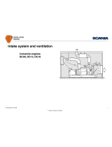
Exhaust system
Industrial engines
DC09, DC13, DC16
333 380

INSTALLATION
MANUAL
©
Scania CV AB 2016, Sweden
01:04 Issue 10 en-GB 2
Sound reduction.......................................................................................................3
Exhaust noise....................................................................................................... 3
Exhaust system design ........................................................................................ 5
Connection of exhaust system to engine ................................................................9
V-clamp............................................................................................................... 9
Stage III B/Tier 4i and less restrictive emission laws ....................................... 10
Stage IV/Tier 4f................................................................................................. 16
Exhaust back pressure ..........................................................................................18
Exhaust back pressure for all engine types ....................................................... 18
Exhaust back pressure Stage III B/Tier 4i......................................................... 19
Exhaust back pressure for Stage IV/Tier 4f ...................................................... 20
Measuring exhaust back pressure...................................................................... 21
Insulating the exhaust system...............................................................................24
Insulation of SCR components.......................................................................... 25
Insulation of Stage IV/Tier 4f engines .............................................................. 25
Protection against water ingress ..........................................................................27
Multi-engine installation.......................................................................................28
Dimensioning the exhaust system ........................................................................30
Calculation example.......................................................................................... 31

INSTALLATION
MANUAL
©
Scania CV AB 2016, Sweden
Sound reduction
01:04 Issue 10 en-GB 3
Sound reduction
Assess the need for sound reduction in new installations from case to case, based on
the applicable conditions in relation to noise requirements, length and type of exhaust
system, location of the exhaust system outlet etc.
Some form of sound reduction is required in most installations.
The thermal insulation of the exhaust system affects the sound level. A thermally in-
sulated system can result in a higher noise level than an uninsulated system.
This document contains information on SCR components. More detailed information
on the SCR system can be found in the SCR system installation manual.
Exhaust noise
The table shows undamped exhaust noise measured 1 metre after the turbocharger at
full power output.
Engine Power (kW) Engine speed (rpm) Sound level (dBA) Most important one-third octave
bands (Hz)
DC09 202-243 1,500 115 63 and 125
1,800 and 2,100 117 80 and 160
257-294 1,500 117 63 and 125
1,800 and 2,100 119 80 and 160
DC13 257-316 1,500 115 80 and 160
1,800 and 2,100 117 100 and 200
331-405 1,500 118 80 and 160
1,800 and 2,100 120 100 and 200

INSTALLATION
MANUAL
©
Scania CV AB 2016, Sweden
Sound reduction
01:04 Issue 10 en-GB 4
The most important frequency range for exhaust noise is between 50 and 500 Hz. The
exhaust flow in the system can generate hissing sounds, e.g. at sharp bends and edg-
es. This phenomenon occurs higher up in the frequency range and is effectively
dampened with an absorption silencer (e.g. glass fibre).
Vibrations in the silencer casing can also generate noise. For this reason, avoid si-
lencers with flat surfaces.
DC16 405 1,500 116 100 and 200
1,800 and 2,100 119 125 and 250
478-515 1,500 118 100 and 200
1,800 and 2,100 121 125 and 250
Engine Power (kW) Engine speed (rpm) Sound level (dBA) Most important one-third octave
bands (Hz)

INSTALLATION
MANUAL
©
Scania CV AB 2016, Sweden
Sound reduction
01:04 Issue 10 en-GB 5
Exhaust system design
Position the silencer as close to the end of the exhaust system as possible. In order to
obtain the best noise reduction, there should only be a short tailpipe after the silencer
(0.8-1.5 m) as shown in the chart.
• For all-speed engines, read the specified maximum speed for the engine.
• For single-speed engines, read the operating speed of the engine.
If the silencer cannot be positioned close to the exhaust system outlet because of a
lack of space, it should be placed as close to the engine as possible. This location is,
however, unfavourable in silencing terms if the pipes beyond it are long. It may be
advisable to install another silencer near to the outlet.
Note:
Sharp exhaust pipe bends close to the outlet increase the risk of hissing sounds.
Exhaust outlet
Design the exhaust system so that the exhaust gases are not reflected against vertical
walls, since this results in increased noise level.
Position the exhaust outlet so that no exhaust gases can be drawn into the engine in-
take. If exhaust gases are drawn into the intake, intake air temperature increases rap-
idly. The exhaust gases contain soot particles so there is also a risk of the air filter
becoming blocked.
WARNING!
Position the exhaust outlet so that exhaust gases cannot penetrate areas occupied by
people, e.g. residential buildings.
1
2
3
1200
2.0
L(m)
rpm
1.8
1.6
1.4
1.2
1.0
0.8
1500 1800 2100 2400
337 694
Graph for determining the longest length of tailpipe.
1. DCI9.
2. DC13.
3. DC16.

INSTALLATION
MANUAL
©
Scania CV AB 2016, Sweden
Sound reduction
01:04 Issue 10 en-GB 6
Example
If 2 silencers are used in the system, they should be positioned in series at a distance
of 2/3 of the length of the tailpipe and with the silencer used to dampen high-frequen-
cy noise furthest away from the engine.
Since the pipes which form part of an exhaust system also operate as silencers, it is
important that they are dimensioned correctly.
Note:
The exhaust back pressure increases with the number of pipe bends and with in-
creased pipe length. This leads to higher fuel consumption and loss of power.
IMPORTANT!
The installer is responsible for ensuring that the exhaust system is well sealed during
installation. He is also responsible for ensuring that the pipe and silencer suspension
is designed in such a way that system leaks cannot arise during operation.

INSTALLATION
MANUAL
©
Scania CV AB 2016, Sweden
Sound reduction
01:04 Issue 10 en-GB 7
Examples of long exhaust systems (i.e. longer than 5 metres) with designs which aid
sound reduction.
Examples of short exhaust systems with designs which aid sound reduction.
L = Length of tailpipe, determined from graph.
a = 2/3 of L. Length a is less significant in exhaust systems with only one silencer.
338 555
338 554
aL
338 556
L
a
338 557
L
a
a
L
338 558

INSTALLATION
MANUAL
©
Scania CV AB 2016, Sweden
Sound reduction
01:04 Issue 10 en-GB 8
SCR system
For engines with an SCR system, in most cases the exhaust system needs to be sup-
plemented by a silencer.
More information on the positioning of SCR components can be found in the SCR
system installation manual.
Oxidation catalytic converter
The oxidation catalytic converter provides a sound reduction of approximately
1.5 dB from 500 Hz and higher frequencies. At lower frequencies, the oxidation cat-
alytic converter has no sound reducing effect.
aL
2
1
3 4
337 506
1. Oxidation catalytic converter.
2. Evaporator or hydrolysis catalytic converter.
3. SCR catalytic converter.
4. Silencer.

INSTALLATION
MANUAL
©
Scania CV AB 2016, Sweden
Connection of exhaust system to engine
01:04 Issue 10 en-GB 9
Connection of exhaust system to engine
There should always be a flexible connection between the exhaust system and the en-
gine which absorbs the movement of the engine and changes in length in the exhaust
system due to temperature changes. A flexible connection can consist of the Scania
exhaust bellows. Position the flexible connection as close to the turbocharger con-
nection as possible.
IMPORTANT!
The weight of the exhaust system must not load the exhaust bellows or turbocharger.
Therefore, place a suspension point immediately after the flexible connection.
The illustration to the right shows the recommended installation of the exhaust sys-
tem.
If the exhaust pipes are very long or if the exhaust system has a relatively long hori-
zontal part between 2 vertical parts, several flexible connections may be required in
the system. There must then be a fixed anchorage point on one side of the vertical
exhaust bellows and a suspension which allows axial movement on the other side.
V-clamp
Scania pipe sections have flanges secured with V-clamps.
Note:
The V-clamp must not be used to force together joints, but only to fix the flanges.
1
3
4
5
2
369 3
11
Recommended installation of exhaust system.
1. Turbocharger.
2. Exhaust pipe bend.
3. Exhaust bellows.
4. Exhaust pipe.
5. Bracket.
338 567

INSTALLATION
MANUAL
©
Scania CV AB 2016, Sweden
Connection of exhaust system to engine
01:04 Issue 10 en-GB 10
Stage III B/Tier 4i and less restrictive emission laws
Exhaust pipe bends
The engines can be equipped with a 90° exhaust pipe bend on the turbocharger ex-
haust outlet. The exhaust pipe bend can be fitted at different angles and rotated 360°
around the connection with the turbocharger.
The exhaust pipe bend is connected to the turbocharger with a V-clamp.
The exhaust pipe bend outlet has a flange that is connected with a V-clamp. It is usu-
ally connected directly to the Scania exhaust bellows.
Exhaust pipe bends for DC09 and DC13
1. DC09 071A.
2. Other DC09 engines and DC13 072/073A.
148
195
Ø185.3
195
175
100
Ø185.3
12
335 011

INSTALLATION
MANUAL
©
Scania CV AB 2016, Sweden
Connection of exhaust system to engine
01:04 Issue 10 en-GB 11
Exhaust pipe bends for DC13 and DC16
1. DC13 and DC16. Does not apply to DC13 072/073A and DC16 071A.
2. DC16 071A.
Weld flanges for connection to turbocharger
1. Weld flange for DC09 and DC13 072/073A, is connected using V-clamp with
part number 1 433 190.
2. Weld flange for DC13 and DC16, connected using V-clamp with part number
1 404 764. Does not apply to DC13 072/073A and DC16 071A.
1
2
Ø185,3
Ø185,3
145
128
129
129
338 665
338 664
Ø102
1
2
Ø125
Ø90
24
5
35
4
Ø115

INSTALLATION
MANUAL
©
Scania CV AB 2016, Sweden
Connection of exhaust system to engine
01:04 Issue 10 en-GB 12
Exhaust bellows
The Scania exhaust bellows consists of 2 flexible sections with several layers of cor-
rugated stainless steel plate that are connected to a short pipe. The exhaust bellows
can absorb both longitudinal and lateral movements. It allows a maximum simulta-
neous lateral movement of ±20 mm and a longitudinal movement of ±10 mm.
The exhaust bellows has an inside diameter of 127 mm and flanges that are secured
with a V-clamp. It is supplied with a loose flange that is welded to the pipe which is
to be connected to the exhaust bellows.
The loose flange supplied with the exhaust bellows can be selected with different in-
side diameters (A) for connection to different pipe diameters. The table below shows
the available inside diameters for the flange.
Use the sealant with part number 1 373 091.
A DC09 DC13 DC16
Ø 114 mm x x x
Ø 130 mm x x x
Ø 155 mm x x
338 559
±10 mm
20 mm20 mm
300 mm
338 561
Ø185
Ø170
0.5±0.05
A
8
20°
338 562

INSTALLATION
MANUAL
©
Scania CV AB 2016, Sweden
Connection of exhaust system to engine
01:04 Issue 10 en-GB 13
Connections to SCR system
Evaporator and hydrolysis catalytic converter
Depending on what the engine order specifies, the weld flange for the evaporator or
hydrolysis catalytic converter is available with 3 different inside diameters (A): 114,
130 and 155 mm. The weld flange is made from stainless steel.
Connect the flange to the evaporator or hydrolysis catalytic converter with the V-
clamp with part number 1 380 137.
Use the sealant with part number 1 373 091.
SCR catalytic converter
Depending on what the engine order specifies, the weld flange for the SCR catalytic
converter is available with 3 different inside diameters (A): 114, 130 and 155 mm.
The weld flange is made from stainless steel.
Connect the flange to the SCR catalytic converter using the V-clamp with part num-
ber 1 863 832.
338 561
Ø185
Ø170
0.5±0.05
A
8
20°
338 562
313 132
Ø140
Ø123
A
20°
2
R4

INSTALLATION
MANUAL
©
Scania CV AB 2016, Sweden
Connection of exhaust system to engine
01:04 Issue 10 en-GB 14
Hydraulic exhaust brake
A hydraulic exhaust brake can be installed on all engines with a low turbocharger
provided the engine has a hydraulic installation. The hydraulic exhaust brake consists
of a pipe bend with a damper and a hydraulic cylinder.
DC09 and DC13
Connect the hydraulic oil pipe to the connection (3) on the hydraulic cylinder (4):
• Connection dimension: M12x1.5.
• Tightening torque: 20±2 Nm.
• Maximum recommended hydraulic pressure: 15-18 bar.
REQUIREMENT!
Check the exhaust back pressure when installation is complete. The maximum ex-
haust back pressure from the exhaust brake is 5 bar.
The exhaust brake has an inside diameter of 107 mm and an outside diameter of 127
mm for connection to the exhaust system. The exhaust brake can be connected to the
exhaust bellows shown in this document.
IMPORTANT!
The exhaust system should be fitted so that there are no stresses in the system. Tight-
en the V-clamp after the engine has warmed up to working temperature for the first
time.
4
1
2
3
335 502
1. Exhaust brake.
2. V-clamp.
3. Connection for hydraulic oil pipe.
4. Hydraulic cylinder.

INSTALLATION
MANUAL
©
Scania CV AB 2016, Sweden
Connection of exhaust system to engine
01:04 Issue 10 en-GB 15
DC16
Connect the hydraulic oil pipe to the connection (4) on the hydraulic cylinder (3):
• Connection dimension: M12x1.5.
• Tightening torque: 20±2 Nm.
• Maximum recommended hydraulic pressure: 15-18 bar.
REQUIREMENT!
Check the exhaust back pressure when installation is complete. The maximum ex-
haust back pressure from the exhaust brake is 5 bar.
The exhaust brake has an inside diameter of 122 mm and an outside diameter of 143
mm for connection to the exhaust system. The exhaust brake can be connected to the
exhaust bellows shown in this document.
IMPORTANT!
The exhaust system should be fitted so that there are no stresses in the system. Tight-
en the V-clamp after the engine has warmed up to working temperature for the first
time.
1
2
3
4
5
335 503
1. V-clamp.
2. Exhaust brake.
3. Hydraulic cylinder.
4. Connection for hydraulic oil pipe.
5. Bracket.

INSTALLATION
MANUAL
©
Scania CV AB 2016, Sweden
Connection of exhaust system to engine
01:04 Issue 10 en-GB 16
Stage IV/Tier 4f
Weld flanges
Weld flanges for connection to exhaust brake and for connecting components in the
SCR system can be selected with different inside diameters (A) for connection to dif-
ferent pipe diameters.
A = Ø 114, 130 or 155 mm. Ø 114 does not apply to DC16.
Weld flange for connection to exhaust brake
The weld flange for connection to the exhaust brake is available to DC09 and DC13.
It is secured using the V-clamp with part number 1 863 831.
For DC13 085A, the weld flange is connected to the exhaust pipe after the turbo-
charger.
Weld flange for connection of components
All components in the SCR system are connected with the same weld flange.
The weld flange for connection of components should be secured using the V-clamp
with part number 1 863 832.
336 526
Ø127
Ø110
A
20°
R4
313 132
Ø140
Ø123
A
20°
2
R4

INSTALLATION
MANUAL
©
Scania CV AB 2016, Sweden
Connection of exhaust system to engine
01:04 Issue 10 en-GB 17
Flange for connecting between SCR components
The flange is used for connecting SCR components, male to male, and secured using
2 V-clamps with part number 1 863 832.
Exhaust bellows
Scania has 2 different types of exhaust bellows for Stage IV/Tier 4f engines:
1. Exhaust bellows for connection to the exhaust brake. This exhaust bellows is
only available to DC09 and DC13. On DC13 085A, the exhaust bellows can be
connected to the exhaust pipe downstream of the turbocharger.
2. Exhaust bellows for connection between the components in the SCR system.
The Scania exhaust bellows for connection to the exhaust brake can absorb longitu-
dinal movements by ±10 mm. The exhaust bellows is secured against the exhaust
brake using the V-clamp with part number 1 863 831.
The Scania exhaust bellows for connecting between the components can absorb both
longitudinal and lateral movements. It allows a maximum simultaneous lateral
movement of ±20 mm and a longitudinal movement of ±10 mm. The exhaust bellows
can be supplied with or without weld flange. It is secured using the V-clamp with part
number 1 863 832.
IMPORTANT!
The exhaust bellows for connection to the exhaust brake must not be insulated. Insu-
lation increases the risk of fire.
337 519
Ø123
Ø140
2
20˚
20˚
12
2020
190 10 mm
+
_
386 10 mm
+
_
336 775
1. Exhaust bellows for connection to exhaust brake.
2. Exhaust bellows for connection between the components in the SCR system.

INSTALLATION
MANUAL
©
Scania CV AB 2016, Sweden
Exhaust back pressure
01:04 Issue 10 en-GB 18
Exhaust back pressure
Exhaust back pressure for all engine types
The back pressure in the exhaust system must not exceed the maximum recommend-
ed exhaust back pressure, including silencers. A higher exhaust back pressure leads
to increased fuel consumption and a loss of power.
The maximum recommended exhaust back pressure is 100 mbar for all engines, ex-
cept for engines with an SCR system listed in the tables on the following pages.
If the exhaust back pressure is above the maximum recommended exhaust back pres-
sure, this has a negative impact on engine performance.
REQUIREMENT!
Check the exhaust back pressure when installation is complete.

INSTALLATION
MANUAL
©
Scania CV AB 2016, Sweden
Exhaust back pressure
01:04 Issue 10 en-GB 19
Exhaust back pressure Stage III B/Tier 4i
Engine Engine power (kW) Basic exhaust back pressure
1
(mbar)
1. Exhaust back pressure for evaporators or hydrolysis catalytic converters and SCR catalytic converters is included.
Maximum recommended exhaust back pressure
(mbar)
DC09 202 130 230
234 160 260
243 170 270
257 180 280
276 190 290
294 200 300
DC13 257 160 260
294 180 280
331 200 300
364 220 320
405 240 340
DC16 405 300 400
478 340 440
515 360 460

INSTALLATION
MANUAL
©
Scania CV AB 2016, Sweden
Exhaust back pressure
01:04 Issue 10 en-GB 20
Exhaust back pressure for Stage IV/Tier 4f
Engine Engine power (kW) Engine speed (rpm) Basic exhaust back pressure
1
(mbar)
1. Exhaust back pressure for any oxidation catalytic converter, evaporator and SCR catalytic converter is included.
Maximum recommended exhaust back pressure
(mbar)
DC09 202 2,100 215 265
232 2,100 245 295
243 2,100 248 298
257 2,100 253 303
276 2,100 255 305
294 2,100 260 310
202 1,800 170 230
214 1,800 180 240
202 1,800 170 230
237 1,800 200 260
DC13 294 2,100 250 300
331 2,100 280 330
368 2,100 320 370
405 1,900 360 410
257 1,800 210 260
283 1,800 225 275
257 2,100 240 290
DC16 405 2,100 330 400
478 2,100 380 440
493 2,100 405 460
566 2,100 450 500
/