Page is loading ...

B43A224014
(24+230V)
www.seip.com
Wichtige Informationen zur Programierung des externen
Empfängers:
Der Empfänger lernt automatisch alle vier Bedientaster des MIDI-Hand-
senders. D.h., wenn ein Taster eingelernt wurde, sind alle anderen eben-
falls im Empfänger gespeichert! Ebenso verhält es sich mit den beiden
Tastern des MINI-Handsenders.
Folgend die Kanalbelegungen der Handsendertasten:
Kanal 1 des Handsenders ist immer auch Kanal 1 am Funkempfänger.
Ebenso verhält es sich mit dem 2., 3., und 4. Kanal.
Erlernung eines Handsenders:
1) Drücken Sie die LERN-Taste bis die rote LED zu blinken beginnt
2) Drücken Sie kurz eine beliebige Taste am Handsender
3.) Die rote LED stoppt zu blinken; der Handsender wurde erfolgreich
programmiert
Löschen des Empfängerspeichers:
1) Halten Sie die LERN-Taste für ca. 5 Sekunden gedrückt: nach einer
Sekunde beginnt die rote LED zu blinken, nach 5 Sekunden brennt sie
durchgängig
2) Lösen Sie die LERN-Taste - alle bereitsprogrammierten Handsender sind
nun aus dem Empfängerspeicher gelöscht.
Maximale Anzahl zu programmierender Handsender: 256 Stück
Werden mehr als 256 Handsender programmiert, wird mit jedem
neuen Sender der zuletzt gelernte Sender aus dem Empfängerspei-
cher gelöscht.
Geeignet für alle SKR433 und SKR433-1 Handsender.
Deutsch
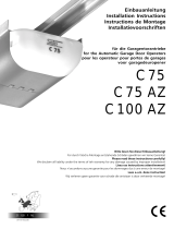
Ext. Empfänger, 4-Kanal, 433MHz
4. Kanal:
Schiebetor
2. Kanal:
Beleuchtung
1. Kanal:
Torantrieb
1. Kanal am Empfänger
muß frei bleiben, da bereits
für Torantrieb verwendet!
Antennenstecker
DIP-Schalter:
Impuls- oder Per-
manentschaltung
für jeden Kanal
wählbar (Standar-
deinstellung ist
Impuls (OFF)).
Torantrieb mit eige-
nem Empfänger; 1.
Kanal des Senders
ist eingelernt
Beispielkon guration
Anschlüsse
Anschlüsse / Bestandteile des Empfängers
Anschlüsse zur Ansteuerung externer Komponenten
A+B potentialfreier Anschluß, 1. Kanal
D+E
C+E
potentialfreier Anschluß, 2. Kanal (NO)
potentialfreier Anschluß, 2. Kanal (NC)
F+G potentialfreier Anschluß, 3. Kanal
H+I potentialfreier Anschluß, 4. Kanal
Stromversorgung (Nur eine Versorgungsart wählen, niemals 24V und 230V
gleichzeitig anschließen!)
J+K Stromversorgung 230V
L+M Stromversorgung 24V
DIP-Schalter
Über die DIP-Schalter wird zwischen den Modi „Dauer“ und „Impuls“ gewählt.
„Impuls“ entspricht dem normalen Tastbetrieb - das Relais wird für die Dauer
der Impulsgebung angezogen und bei Lösen der Handsendertaste wieder gelöst.
Impuls ist die Standardeinstellung zur Ansteuerung von Torantrieben!
„Dauer“ entspricht dem Funktionsprinzip eines Lichtschalters: der erste Taster-
impuls zieht das Relais an. Das Relais bleibt solange angezogen, bis ein zweiter
Tasterimpulse empfangen wird.
Die Funktionen „Impuls“ oder „Dauer“ sind für jeden Kanal separat einstellbar:
DIP
Nr. 1
ON: „Dauer“ für 1. Kanal
OFF: „Impuls“ für 1. Kanal
DIP
Nr. 2
ON: „Dauer“ für 2. Kanal
OFF: „Impuls“ für 2. Kanal
DIP
Nr. 3
ON: „Dauer“ für 3. Kanal
OFF: „Impuls“ für 3. Kanal
DIP
Nr. 4
ON: „Dauer“ für 4. Kanal
OFF: „Impuls“ für 4. Kanal
MINI
1
2
rote LED
HF-
Modul
LERN-
Taster
A B
1.
C D E
2.
F G
3.
H I
4.
J K
230V
L M
24V
MIDI
1
2
3
4

B43A224014
(24+230V)
www.seip.com
Important information on the external receiver:
The receiver will automatically store all four hand-transmitter buttons in
its memory. E.g. once one hand-transmitter button is programmed into
the receiver, all other transmitter buttons are automatically also
programmed in. The same applies to the two buttons on the MINI-trans-
mitter.
The channels on the hand-transmitter are:
Channel 1 on the hand-transmitter always is channel 1 on the receiver.
The same applies to channels 2, 3 and 4.
Before starting the programming procedure, please check that the anten-
na is plugged onto the receiver!
Registering a transmitter with the receiver:
1) Press the learn-button for approx. 1 Sec. until the red LED starts
ashing
2) Press any hand-transmitter button and release it
3) The receivers‘ LED stops ashing and stays on until you release the
hand-transmitter button.
Cancelling the receivers‘ memory:
1) Press the LEARN-button - after one second the red LED starts ashing:
keep the LEARN-button pressed for a further 5 seconds until the red LED-
light stays on permanently. Release the LEARN-button and the memory is
completely cancelled.
Maximum no. of hand-transmitters: 256
When you try to register more than 256 hand-transmitters with
one receiver, then the latest registered hand-transmitter will be
overwritten by the new hand-transmitter.
For use with all SKR433 and SKR433-1 hand transmitters.
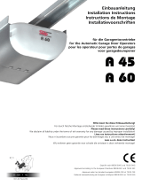
Sample Con guration
English
Ext. Receiver, 4-channel, 433 MHz
Fourth
channel for
sliding door
Second channel
for ext. light
First channel
for garage
door operator
The rst channel on the ext. receiver
must remain unused, as the rst channel
is already in use for the garage door
operator
A B
1.
First channel is
programmed for
the garage door
operator
Connections and Parts of the receiver
Connector (output signals for external devices)
A + B oating connector, rst channel (NO)
D + E
C + E
oating connector, second channel (NO)
oating connector, second channel (NC)
F + G oating connector, third channel (NO)
H + I oating connector, fourth channel
Connectors for Power Supply (use either or, not both!)
J + K 230 V Power Supply
L + M 24 V Power Supply
DIP-switches
With the DIP-switches you can change between the modes „permanent“ and
„impulse“.
„Impulse“ is used for items, which only need a short impulse to start running.
The receivers‘ relais will close as long as the hand-transmitters‘ button is pressed
and it will be released, when the hand-transmitters‘ button is released. This is the
standard for garage door operators.
With „Permanent“ the receiver will work light a light-switch: the rst impulse
from the hand-transmitter will close the relais and it will remain closed until the
next impulse from the hand-transmitter is received.
The functions „impulse“ or „permanent“ may be adjusted seperately for each
channel:
DIP
No. 1
ON: „Permanent“ for 1. channel
OFF: „Impulse“ for 1. channel (standard-setting)
DIP
No. 2
ON: „Permanent“ for 2. channel
OFF: „Impulse“ for 2. channel (standard-setting)
DIP
No. 3
ON: „Permanent“ for 3. channel
OFF: „Impulse“ for 3. channel (standard-setting)
DIP
No. 4
ON: „Permanent“ for 4. channel
OFF: „Impulse“ for 4. channel (standard-setting)
MIDI
1
2
3
4
MINI
1
2
Plug for the antenna LED-lamp
Receiver
Module
LEARN
Button
DIP-switches to
adjust impulse
or permanent
signal (standard
setting: OFF
(=impulse))
C D E
2.
F G
3.
H I
4.
J K
230V
L M
24V
/