Page is loading ...

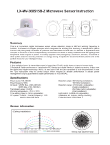
SMS751ELV MICROWAVE MOTION SENSOR electrical and installation specification effective 22/2/2022.
IMPORTANT: IN THE INTEREST OF PRODUCT PERFORMANCE AND SAFETY PLEASE READ THESE INSTALLATION AND WARRANTY INSTRUCTIONS BEFORE INSTALLING THE PRODUCT.
MUST BE INSTALLED
BY A LICENSED
ELECTRICIAN
DIY
SAL products are designed in accordance with all mandatory International and Australian Standards, which require installation
in accordance with AS/NZS3000 by a qualified installer and regular cleaning and maintenance of the equipment. Products are
sold in accordance with the following instructions and SAL standard terms and conditions of sale, available via www.sal.net.au.
Due to continued product and information updates, product data sourced from sal.net.au shall not form part of any contract and or technical performance
guarantee unless expressly confirmed in writing by SAL at the time of order.
SAL National Pty Ltd.
40 Biloela Street
Villawood NSW 2163 ABN 21 633 189 474
Copyright SAL V17 FEB22 |
www.sal.net.au
| Page 1 of 4
General product application requirements (if applicable) :
1. CCT or POWER selections (where supplied) – IMPORTANT, where CCT colour temperature or POWER selection switching is provided, it is important to switch OFF the
power before the selection is made, otherwise equipment damage may occur.
2. Recycling – SAL encourages recycling, please consider the environment when disposing of packaging, batteries & components.
3. Switching or test intervals – For optimum product performance, good design practice does not encourage 24/7 operation of lighting products without the provision
of a routine switching or regulatory test cycle. As a guide for continual operation installations, a twelve (12) hour duration for Industrial and Commercial applications
and a six (6) hour duration for Residential applications should be considered.
4. Product maintenance – In line with the relevant design standards and to protect your investment, it is important to have in place a routine cleaning program that
reflects the installation environment and maintains the product in a clean and functional condition.
IMPORTANT - The supply must be isolated before any product maintenance or cleaning is conducted. In addition, damage to ANY cable or cord supplied with the
product must be addressed as follows; For attachment type X having a specially prepared cable, if the external flexible cable is damaged, it must be replaced by an
equivalent cable exclusively available from the manufacturer or authorised installer. For attachment type Y, if the external flexible cable is damaged, it must be
exclusively replaced by an equivalent cable by the manufacturer or authorised installer. For attachment type Z, if the external flexible cable is damaged, the cable
cannot be replaced and the luminaire must be destroyed.
5. Adverse, corrosive and coastal installation environments – Unless the product is specifically designated for such applications in these installation instructions, which is
supported by a professional maintenance program; installation of equipment in such environments is not recommended.
6. Dimming products – Dimming circuits and product compatibility must be validated by the installer before installation; SAL cannot be responsible for third party
changes in dimmer compatibility.
7. Suspended products – For installation safety, any suspended products must NOT be installed in high air movement spaces or locations subject to impact.
8. Light source replacements – (Non-replaceable light sources) - The light source of the product is deemed not replaceable, when the product reaches its end of life,
the complete product must be replaced by a qualified installer. (Non-user replaceable light sources) - The light source of the product must only be replaced by the
manufacturer or qualified installer. Caution, risk of electric shock.
9. Interior downlights and sensors with remote drivers and electrical accessories – The mounting facilities provided for the device (if any), need only be utilized if in the
application of the product is required by AS/NZS3000. Drivers are not designed for installation environments that restrict conventional airflow.
10. Ripple injection, induced flicker (QLD & NSW regions) – Installations subject to off-peak ripple induced flicker, (which are beyond the manufactures control), should
strongly consider the use of circuit filtering products, or for interior downlight installations, the use of products designed to block the signal interferences, such as the
SAL SFI series.
11. Floodlight products – Unless nominated aiming restrictions or installation parameters apply, products are designed for installation environments between ground and
15 metres in height, subject to the desired optical performance being achieved. For floodlight installation environments that have restricted access (eg: columns
and roof-lines) which are subject to unstable electrical supply or electrical surges (which void warranty), consideration of the installation of an independent surge
protector is strongly recommended.
12. Emergency enabled products – In the interest of transport and safety, emergency products are supplied with the battery disconnected. In addition to specific
emergency commissioning instructions, this battery MUST be connected at the time of installation. Continual use in emergency mode greater than 240 hours without
recharge, will result in battery failure and void battery warranty.
HF System Product installation orientation
Operating ambient min/max (°C) Product application
Operating humidity Pixie connectivity
Storage ambient limit (°C) IP rating*
Storage humidity Power consumption
Enclosed in approved product
5.8GHz ±75MHz
IP rating for interior products: The designated IP rating is “from below the ceiling” unless otherwise specified.
IP rating ALL products: Termination of the product must be made in accordance with the IP rating.
-20 to 40 Interior residential or commercial
10% to 85% RH, NC
-25 to 40 20
< 0.5WMax. 95%
No
Model No. Input (V DC)
Dimension L x W x H (mm)Colour Sensor type
Microwave
SMS751ELV 12 - 24 0-10V Max.30mA sinking current White 122 x 31 x 29
Dim Control Output

STAND-BY LEVEL: 5
13.2.4 Stand-by Light Level Setting
The setting is used to select the desired dimmed light level used in periods of
absence for enhanced comfort and safety.
13.2.5 Stand-by Time Setting
13. Specific installation procedures (if any) - this device must be installed by a licensed electrician:
SAL National Pty Ltd.
40 Biloela Street
Villawood NSW 2163 ABN 21 633 189 474
Copyright SAL V17 FEB22 |
www.sal.net.au
| Page 2 of 4
STAND-BY TIME:6
HOLD TIME: 3,4 0 0 10S
5Min1 0
1Min0 1
1 1 15Min
5
1 50%
0 20%
6
1
030Min
3 4
1
LUX: 2
(Daylight sensor disable)
0
2
1
0
ON
OFF
1
0
ON
OFF
1
0
ON
OFF
1
0
ON
OFF
1
0
ON
OFF SENSITIVITY: 1
13.2.1 Detection Range Setting (Sensitivity)
Detection range is the term used to describe the radii (circular) detection zone
produced on the ground after mounting the sensor light at a height of 2-4m.
050%
1100%
1
13.1 SMS751ELV
WIRING DIAGRAMS
VCC
DIM-
DIM+
0-10V LED DIMMABLE DRIVER
SENSOR COVERAGE
1
0
2 - 4 m
Min: 1.5m
Max: 8m Max: 8m
Height of installation 2 - 4m Detection range Detection angle
13.2.2 Light-control Setting (Lux)
Min:
1.5m
Min:
1.5m
30Lux/300Lux (Daylight sensor is function
(30luxset on/300lux set off))
When lux switch is set to 0, daylight sensor is disabled. only the motion
sensor and corridor function are active. When the lux switch is
set to
1, the daylight sensor is activated.
13.2.3 Hold Time Setting:
The light can be set to 100% brightness for any period of time between
approx-.10sec and a maximum of 15min. Any movement detected before
this time lapse will re-start the timer. It is recommended to select the shortest
time for adjusting the detection zone and for performing the walk
test.
This is the time you would like to keep at the low light level before it’s
completely switched off in the extended absence of movement
13.2
PARAMETER SETTING BY DIP SWITCH:
Consider the picture: 1 set sensitivity; 2 set the lux (daylight sensor function);
3,4 set hold time; 5 set stand-by light level ; 6 set stand-by
time;
12V+

The sensor switches on the
light 100% automatically
when presence is detected.
The light dims to
stand-by level at
20% brigtness after
the 15min hold-
time .
The light dims to
stand-by level at
50% brightness
after the 5min
hold-time .
The light remains in
20% brightness
dimming level at night
if it can not sense any
movement.
The light dims to off
after 30min stand-by
time if no movement
is detected
When the natural light
level exceeds setpoint
(>300lux), the light will
turn off even if the
space is occupied.
The light automatically
turns on at 50% when
natural light is <30lux
even no any
movement detected
The light switches on
at 100% when natural
light is <30lux and
there is movement
detected.
SAL National Pty Ltd.
40 Biloela Street
Villawood NSW 2163 ABN 21 633 189 474
Copyright SAL V17 FEB22 |
www.sal.net.au
| Page 3 of 4
100% on when movement
detected, and dims to 20%
in long absence.
35goes in cycle
at night ...
6
08:10
When the natural light
level exceeds setpoint
(>300lux), the light will
turn off even if the
space is occupied.
6
08:10
1
17:40
3
21:00
5
21:45
4
21:15
3
21:00
5
21:35
4
21:05
1
17:40
The light will turn off
if it can not sense
any movement
after 30min.
The light will stay on
20% brightness if
there is still no
movement
detected.
2
18:10
2
18:10 3 5 goes in cycle
at night ...
100% on when movement
detected, and dims to 50%
at stand-by time, after stand-by
time without motion, the light
goes off.
Setpoint off
13.3
Motion Sensor and Corridor Function (Daylight sensor disabled)
Settings on demostration1:
Setpoint off
Settings on demonstration 3:
Setpoint off
Hold-time Setpoint on Stand-by Dim Stand-by Time
1min / / 20% 30min or +∞
Hold-time Setpoint on Stand-by Dim Stand-by Time
15min 30lux 300lux 20% +∞
Hold-time Setpoint on Stand-by Dim Stand-by Time
5min 30lux 300lux 50% 30min
The light automatically
turns on at 20%
brightness when natural
light is <30lux even no
any movement
detected.
W hen th e lux switch i s s
et
to the 0 p osition the daylight sensor is disabled. (It is a motion sensor with
corridor functi on).
Wh en pe ople leave,
there is no motion sensed for 1
min hold ti me , light dims to
20% stan d-by level .
L ight switches off automatically
after the stand -by period
(30min) or stay on 20% stand-by
level +.
13.4 DAYLIGH T
SEN SOR P RIOR ITIZED
When the lux switch i s s
et
to 1 posi tion the d
aylight
sensor i s activated.
Settings on dem onstrati on
2
:
The light switches on
at 100% brightness
when natural light is
<30lux and there is
movement detected.

SAL National Pty Ltd.
40 Biloela Street
Villawood NSW 2163 ABN 21 633 189 474
Copyright SAL V17 FEB22 |
www.sal.net.au
| Page 4 of 4
14. Warranty – In accordance with SAL’s standard terms and conditions of sale, SAL warrant this product to be free from defects in materials and or workmanship for a
period as stated below for goods not subject to incorrect installation, maintenance, operation, mishandling, environmental, unauthorised modifications or electrical
operating conditions outside the nominated product specification as detailed in these installation instructions. The benefits to you given by this warranty are in addition to
other rights and remedies you have under law. Our goods come with guarantees that cannot be excluded under the Australian Consumer Law. You are entitled to a
replacement or refund for a major failure and compensation for any other reasonably foreseeable loss or damage. You are also entitled to have the goods repaired or
replaced if the goods fail to be of acceptable quality and the failure does not amount to a major failure.
Warranty term – Residential usage (12) months, Commercial usage (12) months, Replaceable Lamps (where supplied) (12) months and Lithium batteries where supplied
(24) months from date of purchase. For New Zealand, please refer to www.sal.co.nz for warranty conditions and service.
How to make a claim?
Step # 1 – Within 30 days of the fault discovery, please contact the original place of the SAL product purchase during standard (local) business hours, with the following
information (a) proof of purchase (b) description and quantity of the claimed fault (c) address of installation. (d) operating hours of the product.
Step # 2 – It is then the responsibility of the original place of product purchase to report the matter to SAL aftersales;
NSW | ACT - SAL National Pty Ltd, 40 Biloela Street Villawood NSW 2163 | P # 02 9723 3099
QLD - SAL National Pty Ltd, 36 Whitelaw Place Richlands QLD 4077 | P # 07 3879 5999
VICT | TAS - SAL National Pty Ltd, 46-48 Keys Road Moorabbin Victoria 3189 | P # 03 9532 3168
SA | NT - SAL National Pty Ltd, Unit 1, 9 Alfred Avenue, Beverley SA 5009 | P # 08 7084 1958
WA - SAL National Pty Ltd, 29 Beringarra Av Malaga WA 6090 | P # 08 9248 7458
NZ - Hamer, 130 Bush Road, Albany, Auckland, 0632 | P # 0800 239 239
Step # 3 - Upon review of your claim and if the product is required to be returned to SAL for technical evaluation, then at the owners expense the product must be
returned to SAL as per the above nominated locations.
Step # 4 - Pending the evaluation, the claim will be validated resulting in the product being repaired or replaced with the same or best equivalent product at the
discretion of SAL, or rejected if the product fault was found to be caused by conditions beyond the responsibility of SAL warranty obligations. Consideration of
installation, product removal, return freight and or testing fees are not the responsibility of SAL.
/