IntelliSense® IS2535/IS2535T Passive Infrared Motion Sensor Product Information
MOUNTING LOCATION GUIDELINES
The IS2535 and IS2535T are designed for use indoors. The sensor can be corner,
wall, or bracket mounted (see Accessories section). Make sure that the sensor
has a clear line-of-sight to the protected area: infrared light cannot penetrate solid
objects, and the sensor must “see” an area in order to detect a moving person.
The sensor should be pointed into the room interior, and away from windows and
heating/cooling sources. Additionally, the sensor should be installed on a surface
where the temperature is similar to that of the area being protected and not pointed
at direct or reflected sunlight.
SPECIAL INSTRUCTIONS FOR INSTALLATION WITH PETS
To take full advantage of the pet immunity in the IS2535/IS2535T, follow the
guidelines below:
•Mount the center of the sensor at 2.3 m (7.5 feet) high.
•Set the sensor to the Low or Lowest sensitivity setting (see Step 7, on page 1),
as required by the application.
•In Lowest sensitivity setting, total combined weight of animals may not exceed
36 kg (80 lb).
•In Low sensitivity setting, total combined weight of animals may not
exceed 18 kg (40 lb).
•The Look-down mask must be installed (see Step 6 - factory installed).
•The pet immune lens (P/N 5-532-719) must be installed (factory installed).
•Mount where pets cannot come within 1.8 m (6 feet) of the sensor by climbing
on furniture, boxes or other objects.
•Do not aim the sensor at stairways or furniture/objects that can be climbed on
by animals.
•Environmental differences and the amount of heat radiated by an animal
will vary the animal immunity levels exhibited by the sensor. Each
installation should be tested to determine the exact level of
attainable animal immunity.
Note: Pet immunity characteristics for this sensor have not been verified by
Underwriter’s Laboratories, Inc.
TAMPER SWITCH
The IS2535T is equipped with normally-closed (NC) cover tamper. Each
sensor is shipped with the cover tamper operational.
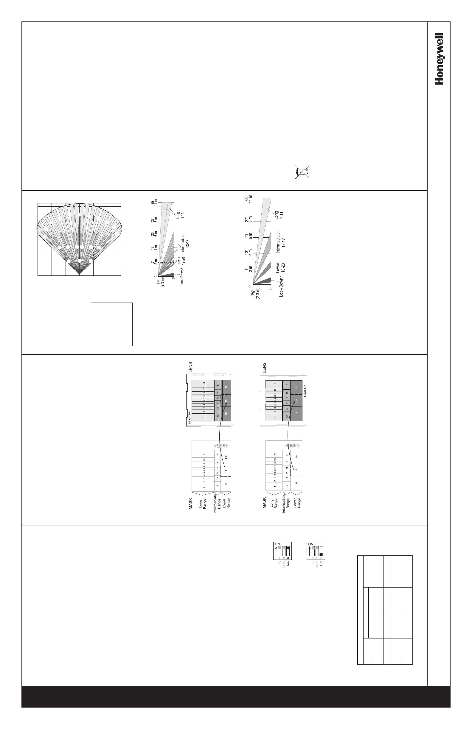
DETECTION PATTERNS
Top View
Wide Angle Pet Immune
Lens (installed)
and
Wide Angle High
Security/Non-Pet
Immune Lens (included)
OPTIONAL LENS DETECTION PATTERN
SPECIFICATIONS
Range:
11 m x 12 m (35’ x 40’)
Pet/Animal Immunity:
36.3 kg, 18.1 kg, 0 kg
(80 lb, 40 lb and 0 lb)
Mounting Height:
2.3 m - 2.7 m (7.5’ - 9’) [Note: 2.3 m
(7.5’) is the optimum mounting height.]
Power requirements:
8.5 - 15.4 VDC (UL:10-14VDC); 17 mA nominal
at 12 VDC, 20 mA max; AC Ripple: 50 to 120
Hz, 3 V peak-to-peak at nominal 12 VDC
Alarm relay:
Form A (normally closed)
30 mA, 24 VDC;
40 Ohms resistance max
Tamper switch (IS2535T):
Form A (normally closed with cover installed)
30 mA, 24 VDC
RFI immunity:
30 V/m, 10 MHz-1000 MHz
PIR white light immunity:
6,500 Lux (min.)
Sensitivity:
Switch selectable (Lowest, Low,
Medium and High)
Operating temperature:
-10o to 55o C (14o to 131o F)
(Indoor use environment)
Relative Humidity:
5% to 95%; non-condensing
Temperature Compensation:
Advanced dual slope
PIR fields-of-view:
Dual element
Pet Immune Lens:
44 long range 36 intermediate
18 lower 4 look-down
High Security/Non-Pet Immune Lens:
22 long range 12 intermediate
6 lower 4 look-down
Dimensions:
11.2 cm x 6.0 cm x 4.0 cm
4-3/8" x 2-1/4” x 1-1/2”
Weight:
89 g (3.14 oz)
Packaged Product: Approx. 155 g (5.47 oz)
Accessories Included:
Mounting hardware
Pet Immune Lens Mask Label
(P/N K9854)
High Security/Non-Pet Immune Lens Mask
Label (P/N K9855)
High Security Non-Pet Immune Lens
(P/N 5-532-477)
Accessories Available:
SMB-10 Swivel Mount Bracket
(P/N 0-000-110-01)
SMB-10C Swivel Mount Ceiling
Bracket (P/N 0-000-111-01)
SMB-10T Swivel Mount Bracket w/
Tamper (P/N 0-000-155-01)
Note: The High Security/Non-Pet Immune
Lens Option and Swivel Mount Brackets
should not be used in pet applications.
EN 50131-1 Compliant Accessories:
SMB-10T Swivel Mount Bracket w/
Tamper (P/N 0-000-155-01)
Approvals/listings:
FCC part 15, Class B verified
IC, ICES-003, Class B verified
CE C-Tick cULus listed
SIA PIR-01
Passive Infrared detector standard
features for false alarm immunity
Finland-IS2535T
FCF: No. RL05145
Enclosure rating: IP30 IK04
IS2535T ONLY:
Tested and certifed to EN 50131-1 and TS
50131-2-2 Security Grade 2; Environmental
Class II by Telefication B.V.
PD6662
Note: In TS 50131-2-2 compliant installations:
mount the sensor at 2.3 m, select the high
sensitivity setting, and install a cover screw
(included).
Suitable for connection to an EN 60950
Class II Limited Power Source in European
installations.
To obtain applicable EU compliance
Declaration of Conformities for this
product, please refer to our Website,
http://www.security.honeywell.com/hsce/
international/index.html. For any additional
information regarding the compliance of
this product to any EU specific require-
ments, please contact:
Quality Assurance Department,
Honeywell Security & Custom Electronics,
Newhouse Industrial Estate
Motherwell,
Lanarkshire ML1 5SB,
Scotland,
United Kingdom.
Tel: +44(0)1698 738200
IMPORTANT: The IS2535/IS2535T should be tested at least once each year.
For proper wiring methods, refer to the National Electrical Code NFPA 70.
© 2004 Honeywell International Inc. • Honeywell and IntelliSense are registered trademarks of Honeywell International Inc. All other
trademarks are the properties of their respective owners. All rights reserved. P/N 5-051-683-00 Rev C
LED OPERATION
To Enable the alarm LED, turn switch S3 ON.
To Disable the alarm LED, turn switch S3 OFF. The LED
will temporarily remain enabled for 10 to 12 minutes.
This feature gives the installer time to walk-test the unit
as explained below.
Automatic Walk-Test Mode with alarm LED disabled
(switch S3 OFF):
After applying power to the sensor, it will warm up for
up to three minutes, and then the LED will temporarily
remain enabled for a 10 minute walk-test period. After
10 minutes, the LED will automatically switch to
disabled.
To restart the 10 minute walk-test mode, switch S3 ON,
and then OFF again.
Side View
Pet Immune Lens
(installed)
* Look-down fingers are enabled only when
the look-down mask is removed (see Step 6).
[Note: Enabling the look-down fingers is not
recommended in pet immune installations.]
Side View
High Security/Non-Pet
Immune Lens (included)
Note:
Detection may occur
beyond the distance
illustrated. A walk-
test is required after
mounting to ensure
proper detection.
MASKING THE LENS
If the installation requires some segments of the detection pattern to be blocked off,
you can mask part of the lens pattern with the lens masking label material (included).
To mask segments of the detection pattern:
•Open the sensor housing and remove the lens (see Step 5).
•Select the appropriate segments to be masked, and
place the lens mask label over the inside of the lens.
•Use Lens Mask K9854 to mask Long, Intermediate and Lower Range segments
on the Pet Immune Lens (P/N 5-532-719, installed).
•Use Lens Mask K9855 to mask Long, Intermediate and Lower Range segments
on the High Security/Non-Pet Immune Lens (P/N 5-532-477, included).
LED
Enabled
LED
Disabled
OPERATION
Enabled
Warm Up
(up to 3 minutes)
Normal
Alarm
Trouble
Disabled
Conditions Alarm LED Alarm Relay
Closed
Closed
Opened
for 3 seconds
See
Troubleshooting
FCC NOTICE: This device complies with Part 15 of the FCC Rules. Operation is subject to the following two conditions: (1) This
device may not cause harmful interference, and (2) this device must accept any interference received, including interference that
may cause undesired operation.
The user is cautioned that changes or modifications not expressly approved by Honeywell could void the user’s authority to operate
this equipment.
NOTE: This equipment as been tested and found to comply with the limits for a Class B digital device, pursuant to Part 15 of the FCC
Rules. These limits are designed to provide reasonable protection against harmful interference in a residential installation. This
equipment generates, uses and can radiate radio frequency energy and, if not installed and used in accordance with the instruc-
tions, may cause harmful interference to radio communications. However, there is no guarantee that interference will not occur in
a particular installation. If this equipment does cause harmful interference to radio or television reception, which can be determined
by turning the equipment off and on, the user is encouraged to try to correct the interference by one or more of the following
measures: 1) Reorient or relocate the receiving antenna; 2) increase the separation between the equipment and receiver; 3) connect
the equipment into an outlet on a circuit different from that to which the receiver is connected; 4) consult the dealer or an experi-
enced radio/television technician for help.
IC Notice: This Class B digital apparatus complies with the Canadian ICES-003.
Cet appareil numérique de la Classe B est conforme à la norme NMB-003 du Canada.
TROUBLESHOOTING
•Symptom: Sensor is not operating.
Corrective Action: Check to make sure the Power terminals are wired correctly. If the
power terminals are wired correctly, and the sensor does not operate when power is
applied, replace the sensor.
•Symptom: Fast Blinking LED -- Trouble condition; two possible causes.
1. Temperature Compensation failure: This sensor checks Temperature once
every 100 ms. When a Temperature Compensation failure occurs, the sensor
defaults to room temperature sensitivity and continues to operate normally
while signalling trouble. The trouble is stored in memory, and when the next
valid alarm condition is detected, the alarm relay latches open.
2. PIR self-test failure: In the absence of PIR signals, the sensor internally checks its
PIR circuit once every ten minutes. If six consecutive self-tests fail, the sensor
signals trouble with its LED, and the relay latches closed. Subsequent detection of
a valid PIR Signal will clear the trouble, and the relay will return to normal operation.
Corrective Action: Replace the sensor.
Slow Blink
OFF
ON for 3
seconds
Fast Blink
Slow Blink
OFF
*See LED
Operation
Fast Blink
0
7’
2m
20’
6m
27’
8m
35’
11 m
0
7’
2m
20’
6m
13’
4m
13’
4m
7’
2m
20’
6m
13’
4m
12
3
4
5
10
9
8
7
6
11
12
13
14
15
16
17
18
19
20

