Hilti HUS3 Operating instructions

Type
Operating instructions

Hilti HUS3: The Ultimate Seismic Fixing Solution for Metal Deck Floors

The Hilti HUS3 is a high-performance mechanical anchor system designed to provide exceptional seismic resistance in concrete-filled metal deck floors. With its unique design and rigorous testing, the HUS3 offers reliable and safe anchoring solutions for a wide range of applications.

Features:

  • Ultimate seismic performance: HUS3 anchors are engineered to meet the stringent requirements of seismic design categories C1 and C2, ensuring the highest level of structural integrity during earthquakes.
  • Versatile application: Suitable for use in both the upper and lower flutes of ComFlor® 60 and 80 metal decks, as well as similar profiles with conforming geometry.
Updated: Oct-21
HILTI COMPOSITE
METAL DECK FLOOR
SEISMIC FIXING
SOLUTION
Hilti HUS3 and HST3 ultimate
performance mechanical anchor
system
Pg. 1/3
HUS3 Screw Anchor
Ultimate-performance screw anchor for seismic actions into ComFlor® 60 and 80
Updated: Oct-21
Pg. 2/3
All data in Table 1 applies to:
Correct installation. See anchor box or Hilti.co.nz for details including hole cleaning and installation torque
No edge distance and spacing influence. Only one anchor can be used in the lower flute at a time with the min. spacing
between anchors along the length of the flute to be at least 3 x hef. This datasheet does not give information for the design of
fasteners in a group.
f’c= 30 MPa concrete. For higher compressive strengths, the tension loads may be increased by (f’c /30)0.5
− αgap = 1.0 (no hole clearance between anchor and fixture) was used to in the formula VRd,s,deck,C1 = αgap x αeq x VRk,s,deck,C1 / gMs,V
In case of connections with hole clearance according to EN 1992-4 Table 6.1, αgap = 0.5 should be used.
Testing in accordance with ACI 355.2 and AC 193. Evaluated in accordance with AC 193 and EAD 330232 and EOTA TR 049
For anchoring into the upper flute, either use Table 1 data below conservatively or refer to ETA-13/1038. Additionally, C2 seismic
performance category is not included in ACI 355.2 and AC 193. C2 seismic performance category may be designed in the upper
flute using all guidelines and parameters provided in ETA-13/1038.
ComFlor® is a registered trademark used in Australia and New Zealand under licence from Tata Steel UK Limited. © Copyright
2017 ComFlor® New Zealand. S&T Stainless Ltd.
Hilti New Zealand Ltd
Level 1, Building B, 600 Great South Rd
P.O. Box 112-030 | Ellerslie, Auckland 1051
P 0800 444 584 | E [email protected]m
Setting Information Sym. Units Nominal anchor diameter (mm)
6 8 10
Nominal bit diameter
domm 6 8 10
Effective min. embedment
hef mm 30 46.4 54.9 58.6 67.1
Nominal embedment
hnom mm 40 60 70 75 85
Min. hole depth
homm 43 70 80 85 95
Setting tool
[1] - -
SIW 22A
Hilti SIW T-A
Loads according to Figure 1
Minimum concrete thickness over upper
flute
hmin,deck mm 70
Minimum distance to edge of lower flute
cmin,deck mm 45 45 45 47 47
Characteristic pullout resistance in non
-
cracked concrete
NRk,p,deck,uncr
kN 7.1 14.7 18.6 16.6 26.6
Characteristic pullout resistance in
cracked concrete
N
Rk,p,deck,cr kN 2.5 11.0 13.9 12.5 15.8
Characteristic pullout resistance, seismic
C1
N
Rk,p,deck,C1 kN 2.5 11.0 13.9 12.5 15.8
Design pullout resistance, seismic C1
N
Rd,p,deck,C1 kN 1.4 7.3 9.3 8.3 10.5
Partial safety factor for pullout resistance
gc- 1.5
Robustness factor for pullout resistance
ginst - 1.2 1.00
Characteristic steel resistance for shear
HUS3
-H, -P, -PS, -C VRk,s,deck kN 10.8 11.4 16.8 20.2 20.2
Characteristic steel resistance for shear,
seismic C1, HUS3
-H, -P, -PS, -C
V
Rk,s,deck,C1 kN 4.3 7.1 9.1 11.3 11.3
Design steel resistance for shear, seismic
C1, HUS3
-H, -P, -PS, -C
V
Rd,s,deck,C1 kN 2.9 4.7 6.1 7.5 7.5
Partial safety factor for steel resistance
for shear
gMs,V - 1.5
Table 1 - Hilti HUS3 anchors tension and shear design data for installation in the soffit of f’c= 30 MPa, normal weight concrete-filled profile deck
assemblies for hammer drilled installations
Figure 1 - Hilti HUS3 in the soffit of concrete filled profile steel deck assemblies
[1] Installation with other impact screw driver of equivalent power is possible. See ETA-13/1038 for full setting details.
ComFlor® 60 or ComFlor® 80 metal deck or
similar profile with conforming geometry
AS 1397 - G500, min 0.75 mm thick
HST3 Expansion Anchor
Ultimate-performance expansion anchor for seismic actions into ComFlor® 60 and 80
Updated: Oct-21
Pg. 3/3
Hilti New Zealand Ltd
Level 1, Building B, 600 Great South Rd
P.O. Box 112-030 | Ellerslie, Auckland 1051
P 0800 444 584 | E [email protected]m
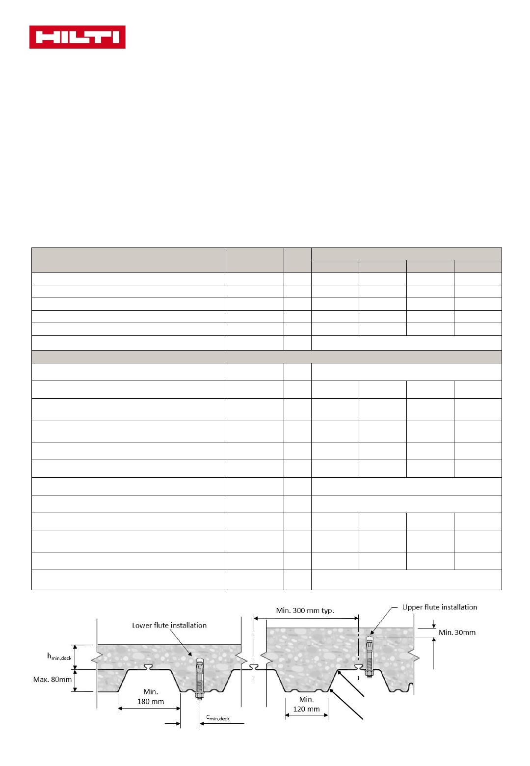
Figure 2 - Hilti HST3 in the soffit of concrete filled profile steel deck assemblies
All data in Table 2 applies to:
Correct installation. See anchor box or Hilti.co.nz for details including hole cleaning and installation torque
No edge distance and spacing influence. Only one anchor can be used in the lower flute at a time with the min. spacing
between anchors along the length of the flute to be at least 3 x hef. This datasheet does not give information for the design of
fasteners in a group.
f’c= 30 MPa concrete. For higher compressive strengths, the tension loads may be increased by (f’c /30)0.5
− αgap = 1.0 (no hole clearance between anchor and fixture) was used to in the formula VRd,s,deck,C1 = αgap x αeq x VRk,s,deck,C1 / gMs,V
In case of connections with hole clearance according to EN 1992-4 Table 6.1, αgap = 0.5 should be used
Testing in accordance with ACI 355.2 and AC 193. Evaluated in accordance with AC 193 and EAD 330232 and EOTA TR 049
For anchoring into the upper flute, either use Table 2 data below conservatively or refer to ETA-98/0001. Additionally, C2 seismic
performance category is not included in ACI 355.2 and AC 193. C2 seismic performance category may be designed in the upper
flute using all guidelines and parameters provided in ETA-98/0001.
ComFlor® is a registered trademark used in Australia and New Zealand under licence from Tata Steel UK Limited. © Copyright
2017 ComFlor® New Zealand. S&T Stainless Ltd.
Setting Information Sym.
Units
Nominal anchor diameter (mm)
810 12 16
Nominal bit diameter
domm 810 12 16
Effective min. embedment
hef mm 47 60 70 85
Nominal embedment
hnom mm 54 68 80 98
Min. hole depth
homm 59 73 88 106
Installation torque
Tinst Nm 20 45 60 110
Methods for application of torque moment
- -
Machine torquing using a Hilti SIW 6AT
-A22 impact wrench with SI-AT
-
A22 adaptive torque module or manual torquing using a torque wrench
Loads according to Figure 2
Minimum concrete thickness over upper flute
hmin,deck mm 70
Minimum distance to edge of lower flute
cmin,deck mm 43 45 47 50
Characteristic pullout resistance in non
-
cracked
concrete
NRk,p,deck,uncr kN 11.9 18.6 20.6 29.2
Characteristic pullout resistance in cracked
concrete
NRk,p,deck,cr kN 8.0 12.7 16.5 20.4
Chacteristic pullout resistance, seismic C1
NRk,p,deck,C1 kN 8.0 12.7 16.5 20.4
Design pullout resistance, seismic C1
NRd,p,deck,C1 kN 5.3 8.4 11.0 13.6
Partial safety factor for pullout resistance
gc-1.5
Robustness factor for pullout resistance
ginst - 1.0
Characteristic steel resistance for shear
VRk,s,deck kN 15.0 24.2 21.4 26.0
Characteristic steel resistance for shear, seismic
C1
VRk,s,deck,C1 kN 13.6 21.9 19.4 22.9
Design steel resistance for shear, seismic C1
VRd,s,deck,C1 kN 9.0 14.6 13.0 15.3
Partial safety factor for steel resistance for shear
gMs,V - 1.25
Table 2 - Hilti HST3 anchors tension and shear design data for installation in the soffit of f’c= 30 MPa, normal weight concrete-filled profile deck
assemblies for hammer drilled installations
ComFlor® 60 or ComFlor® 80 metal deck or
similar profile with conforming geometry
AS 1397 - G500, min 0.75 mm thick
  • Page 1 1
  • Page 2 2
  • Page 3 3

Hilti HUS3 Operating instructions

Type
Operating instructions

Hilti HUS3: The Ultimate Seismic Fixing Solution for Metal Deck Floors

The Hilti HUS3 is a high-performance mechanical anchor system designed to provide exceptional seismic resistance in concrete-filled metal deck floors. With its unique design and rigorous testing, the HUS3 offers reliable and safe anchoring solutions for a wide range of applications.

Features:

  • Ultimate seismic performance: HUS3 anchors are engineered to meet the stringent requirements of seismic design categories C1 and C2, ensuring the highest level of structural integrity during earthquakes.
  • Versatile application: Suitable for use in both the upper and lower flutes of ComFlor® 60 and 80 metal decks, as well as similar profiles with conforming geometry.

Ask a question and I''ll find the answer in the document

Finding information in a document is now easier with AI