Page is loading ...

(800) 999-5099
strongtie.com
Available in
316 and 304
stainless steel
in
",
½
",
",
¾
"
diameters
Stainless-Steel Titen HD
®
Heavy-Duty Screw Anchor

2
© 2018 Simpson Strong-Tie Company Inc. F-A-THDSS18-R
Drill It. Drive It. Forget It.
The Next Era of Stainless-Steel Screw Anchor for
Concrete and Masonry
Titen HD screw anchors are a trusted anchor solution because
they offer the performance that specifiers need and the ease of
installation that contractors demand. Until now, however, they were
not for use in permanent exterior or corrosive environments. The
Titen HD stainless-steel screw anchor for concrete and masonry
sets the new standard for when the job calls for installation in
multiple types of environments. It is the ultimate choice to provide
fast and efficient installation, combined with long-lasting corrosion
resistance for an unsurpassed peace-of-mind.
Innovative — The serrated carbon-steel threads on the tip of
the stainless-steel Titen HD are vital because they undercut the
concrete as the anchor is driven into the hole, making way for the
rest of the threads to interlock with the concrete. In order for these
threads to be durable enough to cut into the concrete, they are
formed from carbon steel that is then hardened and brazed onto the
tip of the anchor.
Corrosion Resistant — For dry, interior applications, carbon-
steel corrosion is not a risk, but in any kind of exterior, coastal
or chemical environment the anchor would be susceptible to
corrosion. With the introduction of the THDSS, there is finally
a state-of-the-art anchor solution that combines the corrosion
resistance of Type 300 Series stainless steel with the undercutting
ability of heat-treated carbon-steel cutting threads.
Installation of stainless-steel Titen HD screw anchor.
Features:
• THDSS is now the first stainless-
steel screw anchor available in ⅝"
and ¾" diameters, in addition to the
" and
½
" sizes
• Ideal for exterior or corrosive
environments
• Less carbon steel, less expansion
• Installs with an impact wrench
or by hand tool
Material: Type 316 and Type 304
stainless steel with carbon-steel lead
threads
Codes: Code listed in IAPMO
UES ER-493 (concrete) and
ICC-ES ESR-1056 (masonry)
Anatomy of the Stainless-Steel Titen HD
®
(THDSS)
The THDSS screw anchor gets its cutting ability from a proprietary bi-metal design that
incorporates a carbon-steel helical-coil thread brazed into the shank of the anchor. The
serrated carbon-steel leading thread cuts a channel for the stainless-steel threads to
engage into.
Innovative carbon-steel thread
effectively cuts the concrete while
significantly limiting the amount of
carbon steel in the anchor.
Deck ledgers
Water treatment plants Outdoor fixtures
Cracked
Concrete
CODE LISTED
Stainless-Steel Titen HD
®
Screw Anchor
Type
304

3
© 2018 Simpson Strong-Tie Company Inc. F-A-THDSS18-R
Don’t Let Other Bi-Metal
Stainless-Steel Anchors
Ruin Your Concrete
Other stainless-steel bi-metal anchors are made by welding
a full carbon segment onto the end of the anchor to facilitate
cutting. With time, the carbon-steel segment embedded in
the concrete is vulnerable to rust. As carbon steel rusts, it
can expand up to ten times its original volume, cracking and
damaging concrete if installed near an edge. The carbon-steel
content of the stainless-steel Titen HD has been minimized.
While the helical-coil thread at the tip of the anchor is hardened
to cut grooves in the concrete during installation, its mass is
likely too small to cause concrete damage when it corrodes.
Carbon-Steel Content Comparison
The ratio of carbon-steel vs. stainless-steel
content in a ½" x 5" stainless-steel screw anchor.
100%
80%
60%
40%
20%
0%
Stainless steel
Carbon steel
Other
½" x 5"
SS Screw
Anchor
18% < 1%
Titen HD
½" x 5"
SS Screw
Anchor
The minimal carbon-steel
content of the stainless-steel
Titen HD greatly reduces the
likelihood of concrete
damage due to corrosion.
Bi-metal anchors can
cause rust-related concrete
failure, including cracking and
spalling at the edge.
The stainless-steel Titen HD screw anchor sets the new
standard for installation in many corrosive environments.
Stainless-Steel Titen HD
®
Screw Anchor

4
© 2018 Simpson Strong-Tie Company Inc. F-A-THDSS18-R
Additional Installation Information
Titen HD
Diameter
(in.)
Wrench Size
(in.)
Recommended
Fixture Hole
Size (in.)
Min. Hole
Depth Overdrill
(in.)
⁄ ½
to
⁄ ¼
½ ¾
to
⁄ ½
⁄ ¾
to
⁄ ½
¾
1
to
⁄ ½
Fixture hole sizes are for structural steel thicker than 12 gauge only. Larger holes are
not required for wood or cold-formed steel members.
Stainless-Steel Titen HD
®
Screw Anchor
Installation
Caution: Holes in steel fixtures to be mounted should match the diameter
specified in the table below if steel is thicker than 12 gauge.
Caution: Use a Titen HD screw anchor one time only — installing the
anchor multiple times may result in excessive thread wear and reduce load
capacity.
Do not use impact wrenches to install into hollow CMU.
Caution: Oversized holes in base material will reduce or eliminate the
mechanical interlock of the threads with the base material and reduce the
anchor’s load capacity.
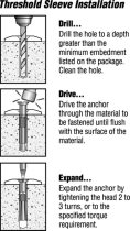
1. Drill a hole in the base material using a carbide drill bit (complying with ANSI
B212.15) with the same diameter as the nominal diameter of the anchor to
be installed. Drill the hole to the specified minimum hole depth overdrill (see
table below) to allow the thread tapping dust to settle, and blow it clean
using compressed air. (Overhead installations need not be blown clean.)
Alternatively, drill the hole deep enough to accommodate embedment depth
and the dust from drilling and tapping.
2. Insert the anchor through the fixture and into the hole.
3. Tighten the anchor into the base material until the hex-washer head
contacts the fixture.
Stainless-Steel Titen HD Screw Anchor Installation
⅜
" dia. = ¼"
½
" dia. = ½"
" dia. =
¼
"
½
",
",
¾
" dia. =
½
"
Stainless-Steel Titen HD Anchor Product Data
Size
(in.)
Model No.
(Type 316)
Model No.
(Type 304)
Drill Bit Dia.
(in.)
Wrench Size
(in.)
Quantity
Box Carton
x 3 THD37300H6SS THD37300H4SS
⁄
50 200
x 4 THD37400H6SS THD37400H4SS
⁄
50 200
x 5 THD37500H6SS THD37500H4SS
⁄
50 100
x 6 THD37600H6SS THD37600H4SS
⁄
50 100
½
x 3 THD50300H6SS THD50300H4SS
½ ¾
25 100
½
x 4 THD50400H6SS THD50400H4SS
½ ¾
20 80
½
x 5 THD50500H6SS THD50500H4SS
½ ¾
20 80
½
x 6 THD50600H6SS THD50600H4SS
½ ¾
20 80
½
x 6
½
THD50612H6SS THD50612H4SS
½ ¾
20 40
½
x 8 THD50800H6SS THD50800H4SS
½ ¾
20 40
x 4 THDB62400H6SS THDB62400H4SS
⁄
10 40
x 5 THDB62500H6SS THDB62500H4SS
⁄
10 40
x 6 THDB62600H6SS THDB62600H4SS
⁄
10 40
x 6
½
THDB62612H6SS THDB62612H4SS
⁄
10 40
x 8 THDB62800H6SS THDB62800H4SS
⁄
10 20
¾
x 4 THD75400H6SS THD75400H4SS
¾
1
10 40
¾
x 5 THD75500H6SS THD75500H4SS
¾
1
5 20
¾
x 6 THD75600H6SS THD75600H4SS
¾
1
5 20
¾
x 7 THD75700H6SS THD75700H4SS
¾
1
5 10
¾
x 8
½
THD75812H6SS THD75812H4SS
¾
1
5 10

5
© 2018 Simpson Strong-Tie Company Inc. F-A-THDSS18-R
Stainless-Steel Titen HD
®
Screw Anchor
Stainless-Steel Titen HD Installation Information
1
Characteristic Symbol Units
Nominal Anchor Diameter (in.)
½ ¾
Installation Information
Nominal Diameter d
a
(d
o
)
4
in.
½
¾
Drill Bit Diameter d
bit
in.
½
¾
Minimum Baseplate Clearance Hole Diameter
2
d
c
in.
½
¾
Maximum Installation Torque
3
T
inst,max
ft.-lbf 40 70 85 150
Maximum Impact Wrench Torque Rating T
impact,max
ft.-lbf 150 345 345 380
Minimum Hole Depth h
hole
in. 2
¾
3
½
3
¾
4
½
4
½
6 6 6
¾
Nominal Embedment Depth h
nom
in. 2
½
3
¼
3
¼
4 4 5
½
5
½
6
¼
Effective Embedment Depth h
ef
in. 1.40 2.04 1.86 2.50 2.31 3.59 3.49 4.13
Critical Edge Distance c
ac
in. 4
½
5
½
6 5
¾
6 6
6
¾
7
Minimum Edge Distance c
min
in. 1
¾
1
¾
1
¾
2
¼
1
¾
1
¾
1
¾
1
¾
1
¾
Minimum Spacing s
min
in. 3 3 4 3 3 3 3 3 3
Minimum Concrete Thickness h
min
in. 4 5 5 6
¼
6 8
½
8
¾
10
Anchor Data
Yield Strength f
ya
psi 98,400 91,200 83,200 92,000
Tensile Strength f
uta
psi 123,000 114,000 104,000 115,000
Minimum Tensile and Shear Stress Area A
se
5
in.
2
0.099 0.1832 0.276 0.414
Axial Stiffness in Service Load Range — Uncracked Concrete
β
uncr
lb./in. 807,700 269,085 111,040 102,035
Axial Stiffness in Service Load Range — Cracked Concrete
β
cr
lb./in. 113,540 93,675 94,400 70,910
1. The information presented in this table is to be used in conjunction with the design criteria of ACI
318-14 Chapter 17 or ACI 318-11 Appendix D, as applicable.
2. The minimum hole size must comply with applicable code requirements for the
connected element.
3. T
inst,max
applies to installations using a calibrated torque
wrench.
4. For the 2006 IBC d
o
replaces d
a
. The notation in parenthesis
is for the 2006 IBC.
5. A
se,N
= A
se,V
= A
se
Stainless-Steel Titen HD Characteristic Tension Strength Design Values
1,5
Characteristic Symbol Units
Nominal Anchor Diameter (in.)
½
¾
Anchor Category 1, 2 or 3 — 1
Nominal Embedment Depth h
nom
in. 2
½
3
¼
3
¼
4 4 5
½
5
½
6
¼
Steel Strength in Tension ( ACI 318-14 17.4.1 or ACI 318-11 Section D.5.1)
Tension Resistance of Steel N
sa
lbf 12,177 20,885 28,723 47,606
Strength Reduction Factor — Steel Failure
2
f
sa
— 0.75
Concrete Breakout Strength in Tension (ACI 318-14 17.4.2 or ACI 318 Section D.5.2)
Effective Embedment Depth h
ef
in. 1.40 2.04 1.86 2.50 2.31 3.59 3.49 4.13
Critical Edge Distance c
ac
in. 4
½
5
½
6 5
¾
6 6
6
¾
7
Effectiveness Factor — Uncracked Concrete k
uncr
— 27 24 27 24 24 24 27 27
Effectiveness Factor — Cracked Concrete k
cr
— 21 17 17 17 17 17 17 21
Modification Factor
Ψ
c,N
— 1
Strength Reduction Factor — Concrete Breakout Failure
3
f
cb
— 0.65
Pullout Strength in Tension (ACI 318-14 17.4.3 or ACI 318-11 Section D.5.3)
Pullout Resistance Uncracked Concrete (f'
c
= 2,500 psi)
N
p,uncr
lbf N/A
4
N/A
4
N/A
4
N/A
4
3,820
5
9,080
7
N/A
4
N/A
4
Pullout Resistance Cracked Concrete (f'
c
= 2,500 psi)
N
p,cr
lbf 1,675
5
2,415
5
1,995
5
N/A
4
N/A
4
N/A
4
N/A
4
N/A
4
Strength Reduction Factor — Pullout Failure
6
f
p
— 0.65
Tension Strength for Seismic Applications (ACI 318-14 17.2.3.3 or ACI 318-11 Section D.3.3.3)
Nominal Pullout Strength for Seismic Loads (f'
c
= 2,500 psi)
N
p,eq
lbf 1,675
5
2,415
5
1,995
5
N/A
4
N/A
4
N/A
4
N/A
4
N/A
4
Strength Reduction Factor for Pullout Failure
6
f
eq
— 0.65
For Sl: 1 in. = 25.4 mm, 1 ft.-lbf. = 1.356 N-m, 1 psi = 6.89 kPa, 1 in
2
= 645 mm
2
, 1 lb./in. = 0.175 N/mm.
1. The information presented in this table is to be used in conjunction with
the design criteria of ACI 318-14 Chapter 17 or ACI 318-11 Appendix D,
as applicable.
2. The tabulated value of
f
sa
applies when the load combinations of Section
1605.2 of the IBC, ACI 318-14 Section 5.3 or ACI 318-11 Section 9.2 are
used, as applicable. If the load combinations of ACI 318-11 Appendix C
are used, the appropriate value of
f
must be determined in accordance
with ACI 318 D.4.4(b), as applicable.
3. The tabulated values of
f
cb
applies when both the load combinations of
Section 1605.2 of the IBC, ACI 318-14 Section 5.3 or ACI 318-11 Section
9.2, as applicable, are used and the requirements of ACI 318-11 D.4.3(c)
for Condition B are met. Condition B applies where supplementary
reinforcement is not provided in concrete. For installations where
complying reinforcement can be verified, the
f
cb
factors described in ACI
318-14 17.3.3(c) or ACI 318-11 D.4.3(c), as applicable, may be used for
Condition A. If the load combinations of ACI 318 Appendix C are used,
the appropriate value of
f
must be determined in accordance with ACI
318 D.4.4(c) for Condition B.
4. N/A denotes that pullout resistance does not govern and does not need to be
considered.
5. The characteristic pullout resistance for greater compressive strengths may be increased
by multiplying the tabular value by (f'
c
/2,500)
0.5
.
6. The tabulated value of
f
p
or
f
eq
applies when both the load combinations of ACI
318-14 Section 5.3 or ACI 318-11 Section 9.2, as applicable, are used and the
requirements of ACI 318-11 D.4.3(c) for Condition B are met. Condition B applies
where supplementary reinforcement is not provided in concrete. For installations where
complying reinforcement can be verified, the
f
p
or
f
eq
factors described in ACI 318-14
17.3.3(c) or ACI 318-11 D.4.3(c), as applicable, may be used for Condition A. If the
load combinations of ACI 318 Appendix C are used, the appropriate value of
φ
must be
determined in accordance with ACI 318 D.4.4(c) for Condition B.
7. The characteristic pullout resistance for greater compressive strengths may be increased
by multiplying the tabular value by (f'
c
/2,500)
0.5
.

6
© 2018 Simpson Strong-Tie Company Inc. F-A-THDSS18-R
Stainless-Steel Titen HD
®
Screw Anchor
Stainless-Steel Titen HD Tension Design Strengths
in Normal-Weight Concrete (f'
c
= 2,500 psi)
Anchor
Dia.
(in.)
Nominal
Embed.
Depth
(in.)
Min.
Concrete
Thickness
h
min
(in.)
Critical
Edge
Distance
C
ac
(in.)
Minimum
Edge
Distance
C
min
(in.)
Tension Design Strength (lb.)
Edge Distances =
C
ac
on all sides
Edge Distances =
C
min
on one side and C
ac
on three sides
SDC A-B
5
SDC C-F
6,7
SDC A-B
5
SDC C-F
6,7
Uncracked Cracked Uncracked Cracked Uncracked Cracked Uncracked Cracked
2
½
4 4
½
1
¾
1,455 1,090 1,090 815 590 985 440 735
3
¼
5 5
½
1
¾
2,270 1,570 1,705 1,175 865 1,100 650 825
½
3
¼
5 6 1
¾
2,225 1,295 1,670 970 745 1,010 560 760
4 6
¼
5
¾
1
¾
3,085 2,185 2,310 1,635 1,240 1,345 930 1,010
4 6 6 1
¾
2,485 1,940 1,860 1,455 1,015 1,245 760 930
5
½
8
½
6
1
¾
5,300 3,760 3,975 2,820 2,370 1,985 1,775 1,490
¾
5
½
8
¾
6
¾
1
¾
5,720 3,600 4,290 2,700 2,370 1,925 1,775 1,440
6
¼
10 7
1
¾
7,360 5,730 5,520 4,295 3,115 2,885 2,335 2,160
1. Tension design strengths are based on the strength design provisions of ACI
318-11 Appendix D or ACI 318-14 Chapter 17.
2. Tabulated values are for a single anchor with no influence of another anchor.
3. Interpolation between embedment depths is not permitted.
4. Strength reduction factor,
f
, is based on using a load combination from ACI
318-11 Section 9.2, Section 1605.2 of the IBC, or ACI 318-14 Section 5.3.
5. The tension design strength listed for SDC (Seismic Design Category) A-B may
also be used in SDC C-F when the tension component of the strength-level
seismic design load on the anchor does not exceed 20% of the total factored
tension load on the anchor associated with the same load combination.
6. When designing anchorages in SDC C-F, the designer shall consider the
ductility requirements of ACI 318-11 Section D.3.3 or ACI 318-14 Section
17.2.3.
7. Tension design strengths in SDC C-F have been adjusted by a 0.75 factor
in accordance with ACI 318-11 Section D.3.3.4.4 or ACI 318-14 Section
17.2.3.4.4.
SD
Stainless-Steel Titen HD Characteristic Shear Strength Design Values
1
Characteristic Symbol Units
Nominal Anchor Diameter (in.)
½ ¾
Anchor Category 1, 2 or 3 — 1
Nominal Embedment Depth h
nom
in. 2
½
3
¼
3
¼
4 4 5
½
5
½
6
¼
Steel Strength in Shear (ACI 318-14 17.5.1 or ACI 318-11 Section D.6.1)
Shear Resistance of Steel V
sa
lbf 3,790 4,780 6,024 7,633 10,422 10,649 13,710 19,161
Strength Reduction Factor — Steel Failure
2
f
sa
— 0.65
Concrete Breakout Strength in Shear (ACI 318-14 17.5.2 or ACI 318-11 Section D.6.2)
Nominal Diameter d
a
(d
o
)
4
in. 0.375 0.500 0.625 0.750
Load Bearing Length of Anchor in Shear l
e
in. 1.40 2.04 1.86 2.50 2.31 3.59 3.49 4.13
Strength Reduction Factor — Concrete Breakout Failure
3
f
cb
— 0.70
Concrete Pryout Strength in Shear (ACI 318-14 17.5.3 or ACI 318-11 Section D.6.3)
Coefficient for Pryout Strength k
cp
— 1.0 2.0 1.0 2.0
Strength Reduction Factor — Concrete Pryout Failure
3
f
cp
— 0.70
Shear Strength for Seismic Applications (ACI 318-14 17.2.3.3 or ACI 318-11 Section D.3.3.3)
Shear Resistance — Single Anchor for Seismic Loads (f'
c
= 2,500 psi)
V
sa,eq
lbf 3,790 4,780 5,345 6,773 9,367 9,367 10,969 10,969
Strength Reduction Factor - Steel Failure
2
f
eq
— 0.65
For Sl: 1 in. = 25.4 mm, 1 lbf. = 4.45 N.
1. The information presented in this table is to be used in conjunction with the
design criteria of ACI 318-14 Chapter 17 or ACI 318-11 Appendix D, as
applicable.
2. The tabulated value of
f
sa
and
f
eq
applies when the load combinations of
Section 1605.2 of the IBC, ACI 318-14 Section 5.3 or ACI 318-11 Section
9.2, as applicable, are used. If the load combinations of ACI 318 Appendix
C are used, the appropriate value of f must be determined in accordance
with ACI 318 D.4.4(b).
3. The tabulated values of
f
cb
and
f
cp
applies when both the load combinations of
Section 1605.2 of the IBC ACI 318-14 Section 5.3 or ACI 318-11 Section 9.2
are used and the requirements of ACI 318-11 D.4.4(c) for Condition B are met.
Condition B applies where supplementary reinforcement is not provided in
concrete. For installations where complying reinforcement can be verified, the
f
cb
and
f
cp
factors described in ACI 318-14 17.3.3(c) or ACI 318-11 D.4.3(c),
as applicable, can be used for Condition A. If the load combinations of ACI
318 Appendix C are used, the appropriate value of
f
cb
must be determined in
accordance with ACI 318 D.4.5(c) for Condition B.
4. The notation in parenthesis is for the 2006 IBC.

7
© 2018 Simpson Strong-Tie Company Inc. F-A-THDSS18-R
Stainless-Steel Titen HD
®
Screw Anchor
Stainless-Steel Titen HD Allowable Tension Loads in Normal-Weight Concrete
(f'
c
= 2,500 psi) — Seismic Load
Anchor
Dia.
(in.)
Nominal
Embed.
Depth
(in.)
Min.
Concrete
Thickness
h
min
(in.)
Critical Edge
Distance
C
ac
(in.)
Minimum
Edge
Distance
C
min
(in.)
Allowable Tension Load (lb.)
Edge Distances =
C
ac
on all sides
Edge Distances =
C
min
on one side and C
ac
on three sides
SDC A-B
4
SDC C-F
5,6
SDC A-B
4
SDC C-F
5,6
Uncracked Cracked Uncracked Cracked Uncracked Cracked Uncracked Cracked
2
½
4 4
½
1
¾
1,020 765 765 570 415 690 310 515
3
¼
5 5
½
1
¾
1,590 1,090 1,195 820 605 770 455 580
½
3
¼
5 6 1
¾
1,560 905 1,170 680 520 705 390 530
4 6
¼
5
¾
1
¾
2,160 1,530 1,615 1,145 870 940 650 705
4 6 6 1
¾
1,740 1,360 1,300 1,020 710 870 530 650
5
½
8
½
6
1
¾
3,710 2,630 2,785 1,975 1,660 1,390 1,245 1,045
¾
5
½
8
¾
6
¾
1
¾
4,005 2,520 3,005 1,890 1,660 1,350 1,245 1,010
6
¼
10 7
1
¾
5,150 4,010 3,865 3,005 2,180 2,020 1,635 1,510
1. Allowable tension loads are calculated based on the strength design provision
of ACI 318-11 Appendix D or ACI 318-14 Chapter 17 using a conversion
factor of a = 1 /0.7 = 1.43. The
conversion factor
a
is based on the load
combination assuming 100% seismic load.
2. Tabulated values are for a single anchor with no influence of another anchor.
3. Interpolation between embedment depths is not permitted.
4. The tension design strength listed for SDC (Seismic Design Category) A-B may
also be used in SDC C-F when the tension component of the strength-level
seismic design load on the anchor does not exceed 20% of the total factored
tension load on the anchor associated with the same load combination.
5. When designing anchorages in SDC C-F, the designer shall consider the
ductility requirements of ACI 318-11 Section D.3.3 or ACI 318-14 Section
17.2.3.
6. Tension design strengths in SDC C-F have been adjusted by a 0.75 factor
in accordance with ACI 318-11 Section D.3.3.4.4 or ACI 318-14 Sectoin
17.2.3.4.4.
Stainless-Steel Titen HD Allowable Tension Loads in Normal-Weight Concrete
(f'
c
= 2,500 psi) — Static Load
Anchor
Dia.
(in.)
Nominal
Embed. Depth
(in.)
Min. Concrete
Thickness
h
min
(in.)
Critical
Edge Distance
C
ac
(in.)
Minimum
Edge Distance
C
min
(in.)
Allowable Tension Load (lb.)
Edge Distances =
C
ac
on all sides
Edge Distances =
C
min
on one side and C
ac
on three sides
Uncracked Cracked Uncracked Cracked
2
½
4 4
½
1
¾
1,040 780 420 705
3
¼
5 5
½
1
¾
1,620 1,120 620 785
½
3
¼
5 6 1
¾
1,590 925 530 720
4 6
¼
5
¾
1
¾
2,205 1,560 885 960
4 6 6 1
¾
1,775 1,385 725 890
5
½
8
½
6
1
¾
3,785 2,685 1,695 1,420
¾
5
½
8
¾
6
¾
1
¾
4,085 2,570 1,695 1,375
6
¼
10 7
1
¾
5,260 4,095 2,225 2,060
1. Allowable tension loads are calculated based on the strength design provision
of ACI 318-11 Appendix D or ACI 318-14 Chapter 17 using a conversion
factor of a = 1.4.The conversion factor a is based on the load combination
1.2D + 1.6L assuming 50% dead load and 50% live load:
1.2(0.5) + 1.6(0.5) = 1.4.
2. Tabulated values are for a single anchor with no influence of another anchor.
3. Interpolation between embedment depths is not permitted.
Stainless-Steel Titen HD Allowable Tension Loads in Normal-Weight Concrete
(f'
c
= 2,500 psi) — Wind Load
Anchor
Dia.
(in.)
Nominal
Embed.
Depth
(in.)
Min.
Concrete
Thickness
h
min
(in.)
Critical
Edge
Distance
C
ac
(in.)
Minimum
Edge
Distance
C
min
(in.)
Allowable Tension Load (lb.)
Edge Distances =
C
ac
on all sides
Edge Distances =
C
min
on one side and C
ac
on three sides
Uncracked Cracked Uncracked Cracked
2
½
4 4
½
1
¾
875 655 355 590
3
¼
5 5
½
1
¾
1,360 935 520 660
½
3
¼
5 6 1
¾
1,335 775 445 605
4 6
¼
5
¾
1
¾
1,850 1,310 745 805
4 6 6 1
¾
1,490 1,165 610 745
5
½
8
½
6
1
¾
3,180 2,255 1,420 1,190
¾
5
½
8
¾
6
¾
1
¾
3,430 2,160 1,420 1,155
6
¼
10 7
1
¾
4,415 3,440 1,870 1,730
1. Allowable tension loads are calculated based on the strength design provision
of ACI 318-11 Appendix D or ACI 318-14 Chapter 17 using a conversion factor
of
a
= 1 /0.6 = 1.67. The conversion factor
a
is based on the load combination
assuming 100% wind load.
2. Tabulated values are for a single anchor with no influence of another anchor.
3. Interpolation between embedment depths is not permitted.

F-A-THDSS18-R
7/18
exp.
12/20
(
800
)
999-5099
strongtie.com
This flier is effective until December 31, 2020, and reflects information available as of July 1, 2018.
This information is updated periodically and should not be relied upon after December 31, 2020.
Contact SimpsonStrong‑Tie for current information and limited warranty or see strongtie.com.
© 2018 SimpsonStrong‑Tie Company Inc. • P.O. Box 10789, Pleasanton, CA 94588
Type 316 stainless steel
• Wastewater treatment
• Fertilizer storage buildings
• Sill plates in coastal environments
• Marine/port restoration
• Light rail (transportation)
• Parking structures
• Tunnels
• Balconies in coastal environments
• Outdoor railings in coastal environments
Type 304 stainless steel
• Stadium seating
• Curtain walls
• Clean rooms
• Central utility plant facilities
• Food-processing facilities
• Ledger bolts for decks
• DOT signs and fixtures
• Agricultural facilities
• Cooling towers
• Pulp and paper mills
• Scaffolding
• Parking structures
• Tunnels
• Balconies
• Refineries
• Breweries and wineries
• Fencing
• Outdoor railings
Stainless-Steel Titen HD
®
Screw Anchor
Type 300 Series stainless-steel screw anchors have different corrosion-resistant properties for different
environments. When matched to the appropriate environment and application, anchors made from Type 300
Series stainless steel will resist the effects of corrosion and maintain their strength and integrity. Type 316 is the
optimal choice for applications in corrosive or extreme environments such as salt water, or when chemical or
corrosive solutions are present. Type 304 is a cost-effective solution for less extreme applications where the
environment may be wet, moist or damp.
For Use in Seating, Catwalks, Machinery, Piping, Railings and More
Deck ledgers General exterior applications
Stadiums
Clean rooms
Food processing Central utility plants
Marine port restoration
Water treatment plants
Parking structures
/