Page is loading ...

#ONFORMSTO!.3)5,
3TD#ERTIFIEDTO
#!.#3!3TD
#.O
312063S
EN
Repair - Parts
Hydraulic, Heated, Plural Component Proportioner. For spraying polyurethane foam and
polyurea coatings. For professional use only.
Not for use in explosive atmospheres.
See page 3 for model information, including
maximum working pressure and approvals.
Important Safety Instructions
Read all warnings and instructions in this manual.
Save these instructions.
TI9830a
Model H-40 Shown
For patent information, see
www.graco.com/patents.

2 312063S
Contents
Models . . . . . . . . . . . . . . . . . . . . . . . . . . . . . . . . . . . 3
Supplied Manuals . . . . . . . . . . . . . . . . . . . . . . . . . . 5
Related Manuals . . . . . . . . . . . . . . . . . . . . . . . . . . . 5
Warnings . . . . . . . . . . . . . . . . . . . . . . . . . . . . . . . . . 6
Temperature Control Diagnostic Codes . . . . . . . . 8
E01: High fluid temperature . . . . . . . . . . . . . . . . 8
E02: High zone current . . . . . . . . . . . . . . . . . . . . 9
E03: No zone current . . . . . . . . . . . . . . . . . . . . . 9
E04: Fluid Temperature Sensor (FTS) or
thermocouple disconnected . . . . . . . . . . . . 10
E05: Circuit board overheated . . . . . . . . . . . . . 10
E06: Communication cable unplugged . . . . . . . 10
Motor Control Diagnostic Codes . . . . . . . . . . . . . 11
Alarms . . . . . . . . . . . . . . . . . . . . . . . . . . . . . . . . 11
Warnings . . . . . . . . . . . . . . . . . . . . . . . . . . . . . . 11
E21: No component A transducer . . . . . . . . . . . 12
E22: No component B transducer . . . . . . . . . . . 12
E23: High fluid pressure . . . . . . . . . . . . . . . . . . 12
E24: Pressure imbalance . . . . . . . . . . . . . . . . . 12
E27: High motor temperature . . . . . . . . . . . . . . 14
E30: Momentary loss of communication . . . . . . 14
E31: Pumpline reversing switch
failure/high cycle rate . . . . . . . . . . . . . . . . . 14
E99: Loss of communication . . . . . . . . . . . . . . . 15
Troubleshooting . . . . . . . . . . . . . . . . . . . . . . . . . . 16
Reactor Electronics . . . . . . . . . . . . . . . . . . . . . . 16
Primary Heaters (A and B) . . . . . . . . . . . . . . . . 18
Hose Heat System . . . . . . . . . . . . . . . . . . . . . . 19
Hydraulic Drive System . . . . . . . . . . . . . . . . . . . 21
Proportioning System . . . . . . . . . . . . . . . . . . . . 23
Repair . . . . . . . . . . . . . . . . . . . . . . . . . . . . . . . . . . . 27
Pressure Relief Procedure . . . . . . . . . . . . . . . . 27
Flushing . . . . . . . . . . . . . . . . . . . . . . . . . . . . . . . 28
Proportioning Pumps . . . . . . . . . . . . . . . . . . . . . 28
Circuit Breaker Module . . . . . . . . . . . . . . . . . . . 30
Electric Motor . . . . . . . . . . . . . . . . . . . . . . . . . . . 31
Motor Control Board . . . . . . . . . . . . . . . . . . . . . 32
Transducers . . . . . . . . . . . . . . . . . . . . . . . . . . . . 34
Electric Fan . . . . . . . . . . . . . . . . . . . . . . . . . . . . 34
Temperature Control Module . . . . . . . . . . . . . . . 35
Primary Heaters . . . . . . . . . . . . . . . . . . . . . . . . . 37
Heated Hose . . . . . . . . . . . . . . . . . . . . . . . . . . . 39
Fluid Temperature Sensor (FTS) . . . . . . . . . . . . 40
Display Module . . . . . . . . . . . . . . . . . . . . . . . . . 42
Inlet Fluid Strainer Screen . . . . . . . . . . . . . . . . . 44
Pump Lubrication System . . . . . . . . . . . . . . . . . 44
Change Hydraulic Fluid and Filter . . . . . . . . . . . 45
Parts . . . . . . . . . . . . . . . . . . . . . . . . . . . . . . . . . . . . 48
Parts Used on All Models . . . . . . . . . . . . . . . . . 54
Parts that Vary by Model . . . . . . . . . . . . . . . . . . 56
Sub Assemblies . . . . . . . . . . . . . . . . . . . . . . . . . 59
Proportioner Assembly . . . . . . . . . . . . . . . . . . . 59
10.2 kW and 6.0 kW Heaters . . . . . . . . . . . . . . . 61
8.0 kW Dual Zone Heater . . . . . . . . . . . . . . . . . 62
7.65 kW Single Zone Heater . . . . . . . . . . . . . . . 63
Hydraulic Cylinder . . . . . . . . . . . . . . . . . . . . . . . 64
Display . . . . . . . . . . . . . . . . . . . . . . . . . . . . . . . . 65
Temperature Control . . . . . . . . . . . . . . . . . . . . . 66
Fluid Manifold . . . . . . . . . . . . . . . . . . . . . . . . . . 67
Circuit Breaker Modules . . . . . . . . . . . . . . . . . . 68
Dimensions . . . . . . . . . . . . . . . . . . . . . . . . . . . . . . . 72
Technical Data . . . . . . . . . . . . . . . . . . . . . . . . . . . . 73
Graco Standard Warranty . . . . . . . . . . . . . . . . . . . 74
Graco Information . . . . . . . . . . . . . . . . . . . . . . . . . 74

Models
312063S 3
Models
H-25 SERIES
H-40 SERIES
H-50 SERIES
Part, Series
Full Load
Peak Amps*
Per Phase
Voltage
(phase)
System
Watts†
Primary
Heater
Watts
Max Flow
Rate◆
lb/min
(kg/min)
Approximate
Output per
Cycle (A+B)
gal. (liter)
Hydraulic
Pressure
Ratio
Maximum Fluid
Working
Pressure
psi (MPa, bar)
255400, F 69 230V (1) 15,960 8,000 22 (10) 0.063 (0.24) 1.91:1 2000 (13.8, 138)
255401, F 46 230V (3) 15,960 8,000 22 (10) 0.063 (0.24) 1.91:1 2000 (13.8, 138)
255402, F 35 400V (3) 15,960 8,000 22 (10) 0.063 (0.24) 1.91:1 2000 (13.8, 138)
255406, F 100 230V (1) 23,260 15,300 22 (10) 0.063 (0.24) 1.91:1 2000 (13.8, 138)
255407, F 59 230V (3) 23,260 15,300 22 (10) 0.063 (0.24) 1.91:1 2000 (13.8, 138)
255408, F 35 400V (3) 23,260 15,300 22 (10) 0.063 (0.24) 1.91:1 2000 (13.8, 138)
Part,
Series
Full Load
Peak Amps*
Per Phase
Voltage
(phase)
System
Watts†
Primary
Heater
Watts
Max Flow
Rate◆
lb/min
(kg/min)
Approximate
Output per
Cycle (A+B)
gal. (liter)
Hydraulic
Pressure
Ratio
Maximum Fluid
Working
Pressure
psi (MPa, bar)
★253400, E 100 230V (1) 23,100 12,000 45 (20) 0.063 (0.24) 1.91:1 2000 (13.8, 138)
253401, E 71 230V (3) 26,600 15,300 45 (20) 0.063 (0.24) 1.91:1 2000 (13.8, 138)
253402, E 41 400V (3) 26,600 15,300 45 (20) 0.063 (0.24) 1.91:1 2000 (13.8, 138)
253407, E 95 230V (3) 31,700 20,400 45 (20) 0.063 (0.24) 1.91:1 2000 (13.8, 138)
253408, E 52 400V (3) 31,700 20,400 45 (20) 0.063 (0.24) 1.91:1 2000 (13.8, 138)
Part,
Series
Full Load
Peak Amps*
Per Phase
Voltage
(phase)
System
Watts†
Primary
Heater
Watts
Max Flow
Rate◆
lb/min
(kg/min)
Approximate
Output per
Cycle (A+B)
gal. (liter)
Hydraulic
Pressure
Ratio
Maximum Fluid
Working
Pressure
psi (MPa, bar)
★253725, E 100 230V (1) 23,100 12,000 52 (24) 0.073 (0.28) 1.64:1 1700 (11.7, 117)
253726, E 71 230V (3) 26,600 15,300 52 (24) 0.073 (0.28) 1.64:1 2000 (13.8, 138)
253727, E 41 400V (3) 26,600 15,300 52 (24) 0.073 (0.28) 1.64:1 2000 (13.8, 138)
256505, E 95 230V (3) 31,700 20,400 52 (24) 0.073 (0.28) 1.64:1 2000 (13.8, 138)
256506, E 52 400V (3) 31,700 20,400 52 (24) 0.073 (0.28) 1.64:1 2000 (13.8, 138)

Models
4 312063S
H-XP2 SERIES
H-XP3 SERIES
*
Full load amps with all devices operating at maximum capabilities. Fuse requirements at various flow rates and mix
chamber sizes may be less.
† Total system watts, based on maximum hose length for each unit:
• Parts 255400 through 255408, 310 ft (94.6 m) maximum heated hose length, including whip hose.
• Parts 253400 through 253408, 253725 through 25372, 256505, and 256506, 410 ft (125 m) maximum heated
hose length, including whip hose.
◆ Maximum flow rate given for 60 Hz operation. For 50 Hz operation, maximum flow rate is 5/6 of 60 Hz maximum
flow.
★ CE approval does not apply.
Part, Series
Full Load
Peak Amps*
Per Phase
Voltage
(phase)
System
Watts†
Primary
Heater
Watts
Max Flow
Rate◆
gpm (lpm)
Approximate
Output per
Cycle (A+B)
gal. (liter)
Hydraulic
Pressure
Ratio
Maximum Fluid
Working
Pressure
psi (MPa, bar)
255403, F 100 230V (1) 23,260 15,300 1.5 (5.7) 0.042 (0.16) 2.79:1 3500 (24.1, 241)
255404, F 59 230V (3) 23,260 15,300 1.5 (5.7) 0.042 (0.16) 2.79:1 3500 (24.1, 241)
255405, F 35 400V (3) 23,260 15,300 1.5 (5.7) 0.042 (0.16) 2.79:1 3500 (24.1, 241)
Part,
Series
Full Load
Peak Amps*
Per Phase
Voltage
(phase)
System
Watts†
Primary
Heater
Watts
Max Flow
Rate◆
gpm (lpm)
Approximate
Output per
Cycle (A+B)
gal. (liter)
Hydraulic
Pressure
Ratio
Maximum Fluid
Working
Pressure
psi (MPa, bar)
253403, E 100 230V (1) 23,100 12,000 2.8 (10.6) 0.042 (0.16) 2.79:1 3500 (24.1, 241)
253404, E 95 230V (3) 31,700 20,400 2.8 (10.6) 0.042 (0.16) 2.79:1 3500 (24.1, 241)
253405, E 52 400V (3) 31,700 20,400 2.8 (10.6) 0.042 (0.16) 2.79:1 3500 (24.1, 241)

Supplied Manuals
312063S 5
Supplied Manuals
The following manuals are shipped with the Reactor
™
Proportioner. Refer to these manuals for detailed equip-
ment information.
Order Part 15M334 for a compact disk of Reactor manu-
als translated in several languages.
Manuals are also available at www.graco.com.
Translations
The Reactor Repair-Parts manual is available in the fol-
lowing languages. See the following chart for specific
languages and corresponding part numbers.
Related Manuals
The following manuals are for accessories used with the
Reactor
™
.
Order Part 15M334 for a compact disk of Reactor manu-
als translated in several languages. Order Part 15B381
for a compact disk of Fusion manual translated in sev-
eral languages.
Reactor Hydraulic Proportioner
Part Description
312062 Reactor Hydraulic Proportioner, Oper-
ation Manual (English)
Reactor Electrical Diagrams
Part Description
312064 Reactor Hydraulic Proportioner, Elec-
trical Diagrams (English)
Proportioning Pump
Part Description
312068 Proportioning Pump Repair-Parts
Manual (English)
Part Language
312063 English
312428 Chinese
312429 Dutch
312430 French
312431 German
312432 Italian
312433 Japanese
312434 Korean
312435 Russian
312436 Spanish
Feed Pump Kits
Part Description
309815 Instruction-Parts Manual (English)
Air Supply Kit
Part Description
309827 Instruction-Parts Manual (English) for
Feed Pump Air Supply Kit
Circulation and Return Tube Kits
Part Description
309852 Instruction-Parts Manual (English)
Heated Hose
Part Description
309572 Instruction-Parts Manual (English)
Circulation Kit
Part Description
309818 Instruction-Parts Manual (English)
Circulation Valve Kit
Part Description
312070 Instruction-Parts Manual (English)
Data Reporting Kit
Part Description
309867 Instruction-Parts Manual (English)
Rupture Disk Assembly Kit
Part Description
309969 Instruction-Parts Manual (English)
Proportioning Pump Repair Kits
Part Description
312071 Seal Kits Instruction-Parts Manual
(English)

Warnings
6 312063S
Warnings
The following warnings are for the setup, use, grounding, maintenance, and repair of this equipment. The exclama-
tion point symbol alerts you to a general warning and the hazard symbol refers to procedure-specific risk. Refer back
to these warnings. Additional, product-specific warnings may be found throughout the body of this manual where
applicable.
WARNING
ELECTRIC SHOCK HAZARD
Improper grounding, setup, or usage of the system can cause electric shock.
• Turn off and disconnect power cord before servicing equipment.
• Use only grounded electrical outlets.
• Use only 3-wire extension cords.
• Ensure ground prongs are intact on sprayer and extension cords.
• Do not expose to rain. Store indoors.
TOXIC FLUID OR FUMES HAZARD
Toxic fluids or fumes can cause serious injury or death if splashed in the eyes or on skin, inhaled, or swallowed.
• Read MSDS’s to know the specific hazards of the fluids you are using.
• Store hazardous fluid in approved containers, and dispose of it according to applicable guidelines.
• Always wear impervious gloves when spraying or cleaning equipment.
PERSONAL PROTECTIVE EQUIPMENT
You must wear appropriate protective equipment when operating, servicing, or when in the operating area of the
equipment to help protect you from serious injury, including eye injury, inhalation of toxic fumes, burns, and hearing
loss. This equipment includes but is not limited to:
• Protective eyewear
• Clothing and respirator as recommended by the fluid and solvent manufacturer
• Gloves
• Hearing protection
SKIN INJECTION HAZARD
High-pressure fluid from gun, hose leaks, or ruptured components will pierce skin. This may look like just a cut, but it
is a serious injury that can result in amputation. Get immediate surgical treatment.
• Engage trigger lock when not spraying.
• Do not point gun at anyone or at any part of the body.
• Do not put your hand over the spray tip.
• Do not stop or deflect leaks with your hand, body, glove, or rag.
• Do not spray without tip guard and trigger guard installed.
• Follow Pressure Relief Procedure in this manual, when you stop spraying and before cleaning, checking, or
servicing equipment.
• Tighten all fluid connections before operating the equipment.
• Check hoses and couplings daily. Replace worn or damaged parts immediately.
FIRE AND EXPLOSION HAZARD
Flammable fumes, such as solvent and paint fumes, in work area can ignite or explode. To help prevent fire and
explosion:
• Use and clean equipment only in well ventilated area.
• Eliminate all ignition sources; such as pilot lights, cigarettes, portable electric lamps, and plastic drop cloths
(potential static arc).
• Keep work area free of debris, including solvent, rags and gasoline.
• Do not plug or unplug power cords or turn lights on or off when flammable fumes are present.
• Ground equipment, personnel, object being sprayed, and conductive objects in work area. See Grounding
instructions.
• Use only Graco grounded hoses.
• Check gun resistance daily.
• If there is static sparking or you feel a shock, stop operation immediately. Do not use equipment until you
identify and correct the problem.
• Do not flush with gun electrostatics on. Do not turn on electrostatics until all solvent is removed from system.
• Keep a working fire extinguisher in the work area.

Warnings
312063S 7
THERMAL EXPANSION HAZARD
Fluids subjected to heat in confined spaces, including hoses, can create a rapid rise in pressure due to the thermal
expansion. Over-pressurization can result in equipment rupture and serious injury.
• Open a valve to relieve the fluid expansion during heating.
• Replace hoses proactively at regular intervals based on your operating conditions.
PRESSURIZED ALUMINUM PARTS HAZARD
Do not use 1,1,1-trichloroethane, methylene chloride, other halogenated hydrocarbon solvents or fluids containing
such solvents in pressurized aluminum equipment. Such use can cause serious chemical reaction and equipment
rupture, and result in death, serious injury, and property damage.
EQUIPMENT MISUSE HAZARD
Misuse can cause death or serious injury.
• This equipment is for professional use only.
• Do not leave the work are while the equipment is energized or under pressure. Turn off all equipment and follow
the Pressure Relief Procedure in this manual when the equipment is not in use.
• Do not operate the unit when fatigued or under the influence of drugs or alcohol.
• Do not exceed the maximum working pressure or temperature rating of the lowest rated system component.
See Technical Data in all equipment manuals.
• Use fluids and solvents that are compatible with equipment wetted parts. See Technical Data in all equipment
manuals. Read fluid and solvent manufacturer’s warnings. For complete information about your material,
request MSDS forms from distributor or retailer.
• Check equipment daily. Repair or replace worn or damaged parts immediately with genuine manufacturer’s
replacement parts only.
• Do not alter or modify equipment.
• Use equipment only for its intended purpose. Call your distributor for information.
• Route hoses and cables away from traffic areas, sharp edges, moving parts, and hot surfaces.
• Do not kink or over bend hoses or use hoses to pull equipment.
• Keep children and animals away from work area.
• Comply with all applicable safety regulations.
MOVING PARTS HAZARD
Moving parts can pinch or amputate fingers and other body parts.
• Keep clear of moving parts.
• Do not operate equipment with protective guards or covers removed.
• Pressurized equipment can start without warning. Before checking, moving, or servicing equipment, follow the
Pressure Relief Procedure in this manual. Disconnect power or air supply.
BURN HAZARD
Equipment surfaces and fluid that’s heated can become very hot during operation. To avoid severe burns, do not
touch hot fluid or equipment. Wait until equipment/fluid has cooled completely.
WARNING

Temperature Control Diagnostic Codes
8 312063S
Temperature Control Diagnostic Codes
Temperature control diagnostic codes appear on tem-
perature display.
These alarms turn off heat. E99 clears automatically
when communication is regained. Codes E03 through
E06 can be cleared by pressing . For other codes,
turn main power OFF then ON to
clear.
E01: High fluid temperature
Causes of E01 Errors
• Thermocouple A or B (310) senses a fluid tempera-
ture above 230°F (110°C).
• Fluid temperature sensor (FTS) senses a fluid tem-
perature above 230°F (110°C).
• Overtemperature switch A or B (308) senses a fluid
temperature above 230°F (110°C) and opens. At
190°F (87°C) the switch closes again.
• Thermocouple A or B (310) fails, is damaged, is not
touching the heater element (307), or has a poor
connection to the temperature control board.
• Overtemperature switch A or B (308) fails in the
open position.
• The temperature control board fails to turn off any
heat zone.
• Zone power wires or thermocouples are switched
from one zone to another.
• Failed heater element where thermocouple is
installed.
• Loose wire
• On 8 kW heater models only: Jumper wire on J1
connector, between module (3) and display (4), is
loose or incorrectly wired.
Checks
Check which zone is displaying the E01 error.
1. Check that connector B is firmly plugged into tem-
perature control module (see F
IG
. 8, page 35).
2. Clean and re-plug connections.
3. Check connections between the temperature con-
trol module and overtemperature switches A and B
(308), and between temperature control module and
thermocouples A and B (310) or FTS (21) [depend-
ing on which zone is displaying E01]. See T
ABLE
6,
page 35. Ensure that all wires are securely con-
nected to connector B.
NOTICE
To prevent damage to soft key buttons, do not
press the buttons with sharp objects such as pens,
plastic cards, or fingernails.
Code Code Name Alarm
Zone
Corrective
Action page
01 High fluid temperature Individual
8
02 High zone current Individual
9
03 No zone current with
hose heater on
Individual
9
04 FTS not connected Individual
10
05 Board overtemperature Individual
10
06 Communication cable
unplugged from module
Individual
10
99 Loss of communication A
15
For hose zone only, if FTS is disconnected at
startup, display will show hose current 0A.
Troubleshooting this equipment requires access to
parts that may cause electric shock or other serious
injury if work is not performed properly. Have a quali-
fied electrician perform all electrical troubleshooting.
Be sure to shut off all power to the equipment before
repairing.

Temperature Control Diagnostic Codes
312063S 9
4. Remove connector B from temperature control mod-
ule, and check continuity of overtemperature
switches A and B, thermocouples A and B, or FTS
by measuring resistance across the pins on the plug
end; see T
ABLE
1.
5. Verify fluid temperature, using an external tempera-
ture sensing device.
• If temperature
is
too high (sensor reading is
229°F [109°C] or above):
6. Check if thermocouples A and B are damaged, or
not contacting the heater element, page 38.
7. To test that temperature control module turns off
when equipment reaches temperature setpoint:
a. Set temperature setpoints far below displayed
temperature.
b. Turn zone on. If temperature rises steadily,
power board is failing.
c. Verify by swapping with another power module.
See Replacing Temperature Control Assem-
bly Modules, page 36.
d. If the swapped module does not fix the problem,
the power module is not the cause.
8. Verify continuity of heater elements with an ohmme-
ter, see page 37.
E02: High zone current
1. Turn main power OFF .
2. Relieve pressure, page 27.
3. Disconnect hose connector (D) at Reactor.
4. Using an ohmmeter, check between the two termi-
nals of the connector (D). There should be no conti-
nuity.
5. Exchange zone module with another one. Turn
zone on and check for error. If error disappears,
replace faulty module.
For hose zone:
If error still occurs, perform Trans-
former Primary Check and Transformer Secondary
Check starting on page 41.
E03: No zone current
1. Check for tripped circuit breaker inside electrical
cabinet or at power source for that zone. Replace
circuit breaker if it trips habitually.
2. Check for loose or broken connection at that zone.
3. Exchange zone module with another one. Turn
zone on and check for error (see page 36). If error
disappears, replace faulty module.
4. If E03 occurs for all zones, the contactor may not be
closing. Verify wiring from heater control to contac-
tor coil.
a.
Hose zone
: test hose continuity, page 39.
b. Perform Transformer Primary Check and
Transformer Secondary Check, starting on
page 41.
Before doing the following checks, note which zone
(A, B, FTS, or all) has high fluid temperature.
Table 1: Sensor Connector Continuity Checks
Pins Description Reading
1 & 2 OT switch A nearly 0 ohms
3 & 4 OT switch B nearly 0 ohms
5 & 6 Thermocouple A 4-6 ohms
8 & 9 Thermocouple B 4-6 ohms
11 & 12 FTS approximately 35
ohms per 50 ft (15.2
m) of hose, plus
approximately 10
ohms for FTS
10 & 12 FTS open
Disconnect whip hose.
When there is a a high current error, the LED on
that zone’s module will turn red while the error is
displayed.
When a no current error occurs, the LED on the
specific zone’s module turns red when the error is
displayed.

Temperature Control Diagnostic Codes
10 312063S
E04: Fluid Temperature Sensor
(FTS) or thermocouple
disconnected
1. Check temperature sensor connections to long
green connector (B) on temperature control module,
page 35. Unplug and re-plug sensor wires.
2. Test fluid temperature sensor continuity with ohm-
meter, page 8.
3. If an error occurred for the hose zone, check FTS
connections at each section of hose.
4. If an error occurred for the hose zone, test FTS by
plugging directly into machine.
5. To verify heater control module is not causing the
problem, use a wire to short-circuit the two pins cor-
responding to the FTS (red and yellow for A or B
zone, red and purple for hose). The display will
show the control heater module temperature.
6. If an error occurred for the hose zone, temporarily
use the current control mode. Refer to Reactor
Operation manual 312062.
E05: Circuit board overheated
1. Check that fan above electrical cabinet is operating.
2. Check that electrical cabinet door is properly
installed.
3. Check for obstructions blocking cooling holes in bot-
tom of electrical cabinet.
4. Clean heatsink fins behind heater control modules.
5. Ambient temperature may be too high. Allow Reac-
tor to cool by moving to a cooler location.
E06: Communication cable
unplugged
1. Unplug and re-plug cable that connects heater con-
trol module to heater module.
2. Replace communication cable if problem persists.
ti9878a
F
Each module has an on-board temperature sensor.
Heat is turned off if module temperature exceeds
185°F (85°C) within the heater module.

Motor Control Diagnostic Codes
312063S 11
Motor Control Diagnostic Codes
Motor control diagnostic codes E21 through E27 appear
on pressure display.
There are two types of motor control codes: alarms and
warnings. Alarms take priority over warnings.
Alarms
Alarms turn off Reactor. Turn main power OFF
then ON to clear.
Warnings
Reactor will continue to run. Press to clear. A
warning will not recur for a predetermined amount of
time (varies for different warnings), or until main power
is turned OFF then ON .
Alarms can also be cleared, except for code 23, by
pressing .
Code Code Name Alarm (A) or
Warning (W)
Corrective
Action
page
21 No transducer (compo-
nent A)
A
12
22 No transducer (compo-
nent B)
A
12
23 High fluid pressure A
12
24 Pressure imbalance A/W (to
select, see
page 32)
12
27 High motor temperature A
14
30 Momentary loss of com-
munication
A
14
31 Pumpline reversing switch
failure/high cycle rate
A
14
99 Loss of communication A
15

Motor Control Diagnostic Codes
12 312063S
E21: No component A
transducer
1. Check transducer A connection at J3 on motor con-
trol board, page 33, and clean contacts.
2. Reverse A and B transducer connections. If error
moves to transducer B (E22), replace transducer A,
page 34. If error does not move, replace motor con-
trol board, page 32.
E22: No component B
transducer
1. Check transducer B connection at J8 on motor con-
trol board, page 33, and clean contacts.
2. Reverse A and B transducer connections. If error
moves to transducer A (E21), replace transducer B,
page 34. If error does not move, replace motor con-
trol board, page 32.
E23: High fluid pressure
1. Relieve pressure. Verify low pressure with analog
gauges. Turn main power OFF then ON
. If error persists, do checks below.
2. If pressure imbalance is set to Warning instead of
Alarm (see page 32), an E23 will occur. See E24:
Pressure imbalance for causes and checks.
E24: Pressure imbalance
Fast E24 Errors
Fast E24 errors occur:
• within 10 seconds of turning the pumps on, or
• as soon as you trigger the gun.
Causes of Fast E24 Errors
• one side of the gun is plugged.
• a pressure transducer has failed.
• damaged pump seals or check valve.
• no feed pressure or empty material drum
• plugged heater.
• plugged hose.
• plugged manifold.
• one PRESSURE RELIEF/SPRAY valve is leaking or
is set to PRESSURE RELIEF/CIRCULATION .
Checks for Fast E24 Errors
• If the gauge readings are very close:
1. Clear the error (page 11) and try running the unit
again.
2. If E24 recurs and the gauge readings are still very
close, a pressure transducer has failed.
Upon initial start-up this diagnostic code will not
cause an alarm for 2 minutes.
If the pressure difference between components A
and B exceeds 500 psi (3.5 MPa, 35 bar), an E24
will occur. This default value is adjustable; see the
operation manual.
E24 can be an alarm or a warning, as desired. Set
DIP switch on motor control board ON for alarm,
OFF for warning. See page 32.
If a fast E24 error occurs, first check the readings of
the analog gauges.

Motor Control Diagnostic Codes
312063S 13
The digital display always shows the higher of the
two pressures. As soon as the higher analog pres-
sure drops below the lower analog pressure, the
display changes to the new higher reading. Knowing
this, the following checks will show which trans-
ducer has failed, or if the motor control board has
failed.
3. For testing purposes only, set DIP switch 2 on the
motor control board to OFF. See page 32. This will
allow the Reactor to continue to run with a pressure
imbalance.
c. Run the unit until pressure is 1000-1500 psi
(7-10.5 MPa, 70-105 bar). Shut down the unit,
clear the alarm, and power back up, but do not
depressurize the unit.
d. Check the analog gauges to see which pressure
is higher, and check if the display matches.
If the higher gauge and display match,
that
transducer is communicating with the motor
control board. Continue with step e.
If the higher gauge and display do not
match,
that transducer is not communicating
with the motor control board. Check wire con-
nections and replace transducer, page 34.
4. To test if the failure is with the transducer or the
socket on the motor control board:
a. Reverse connections at J3 and J8 on the motor
control board.
b. Run the unit until pressure is 1000-1500 psi
(7-10.5 MPa, 70-105 bar).
c. If the problem stays on the same side as before,
replace the motor control board. If the problem
appears to move to the other side, replace the
transducer.
• If the gauge readings are not very close:
2. If you cannot get the pressures to balance:
a. Check for damaged pump seals or check
valves.
b. Check if you’ve run out of material.
c. Check for a plugged fluid path by using the feed
pump to push fluid through the gun manifold.
3. If you are able to balance pressures, try running the
unit.
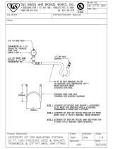
e. Turn pumps off. Reduce pressure of higher
component by slightly turning PRESSURE
RELIEF/SPRAY valve for that component
toward PRESSURE RELIEF/CIRCULATION
, while watching the display and the analog
gauges. As soon as the higher analog pressure
drops below the lower analog pressure, the dis-
play should change to the new higher reading.
Continue reducing the original higher pressure
an additional 200 psi (1.4 MPa, 14 bar); digital
display should stop dropping.
f. Repeat for the other side, to check the other
transducer.
ti9877a
1
Turn valve slightly
to reduce pressure
of higher
1
1. Secure bleed lines in grounded waste containers, or
route back to respective component A or B supply
drum. Reduce pressure of higher component by
slightly turning PRESSURE RELIEF/SPRAY valve
for that component toward PRESSURE
RELIEF/CIRCULATION , until gauges show
balanced pressures.
Turn PRESSURE RELIEF/SPRAY valve only
enough to balance pressure. If you turn it com-
pletely, all pressure will bleed off.
ti9877a
1
Turn valve slightly
to reduce pressure
of higher
1

Motor Control Diagnostic Codes
14 312063S
4. If a fast E24 error occurs again, and the gauges
readings are not very close:
a. Check and clean the gun inlet screens.
b. Check and clean the gun mix chamber impinge-
ment ports and center port. See gun manual.
Slow E24 Errors
Slow E24 errors occur gradually. The pressures are bal-
anced when you begin spraying, but slowly become
imbalanced until an E24 occurs.
Causes of Slow E24 Errors
• one side of the gun is partially plugged.
• the A or B proportioner pump has failed.
• the A or B feed pump has failed.
• the A or B feed pump pressure is set too high.
• the A or B proportioner pump inlet screen is
plugged.
• the hose is not heating properly.
• kinked supply hose.
• bottom of drum is damaged, causing blockage of
feed pump inlet.
• drum is not vented.
E27: High motor temperature
Causes of E27 Errors
• Motor temperature is too high. Reduce pressure,
gun tip size, or move Reactor to a cooler location.
Allow 1 hour for cooling.
• Make sure there is no obstruction to fan airflow.
Ensure that the motor/fan shroud is installed.
• Check that the motor overtemperature wire assem-
bly is plugged into J9 on the motor control board,
page 33.
• If the preceding checks do not correct the problem,
perform the following tests:
1. Turn main power OFF .
2. Allow motor to cool completely. Check continuity
between pins 1 and 2 on connector J9 on the motor
control board, page 32. If the resistance is infinity,
the motor thermal switch or the wire harness is bad.
Check wiring, measure thermal switch continuity at
motor, and replace failed part.
3. Unplug motor from J9 on motor control board. Install
jumper across pins 1 and 2 on board. If error still
occurs, replace motor control board.
4. If the E27 error is still occurring, the problem is with
the motor control board.
E30: Momentary loss of
communication
If communication is lost between the display and the
motor control board, the display will normally show E99.
The motor control board will register E30 (the red LED
will blink 30 times). When communications are recon-
nected, the display may show E30 briefly (no more than
2 seconds). If the display shows E30 continuously, there
is a loose connection causing the display and board to
repeatedly lose and regain communication.
E31: Pumpline reversing switch
failure/high cycle rate
Failure of a pumpline switch or switch mechanism may
result in a high cycle rate, causing an E31 to occur.
Replace the switch or switch mechanism. See Pumps
Do Not Reverse Direction, page 26.
E31 may also occur if the system is modified to produce
a higher flow rate.
Some mix chambers have counter bored impinge-
ment ports, requiring two drill sizes to clean com-
pletely.

Motor Control Diagnostic Codes
312063S 15
E99: Loss of communication
If communication is lost between the motor control dis-
play and the motor control board, or the temperature
control display and the temperature control module, the
affected display will show E99.
1. Check all wiring between the display and the motor
control board and the temperature control module.
Pay close attention to the wire crimping at J13 on
the motor control board (page 33) and (C) on the
temperature control module (page 35). Unplug and
re-plug connectors.
2. Incoming voltage should be 230 Vac. Check the
temperature control module voltage at terminal
block (805) on the circuit breaker module (see page
68). Check the motor control board voltage at
motor/pumps circuit breaker (813), see page 30.
• Check if temperature control module or motor
control board is causing error:
3. Swap display connection on temperature control
module (C) with display connection on motor control
board (J13).
4. If error no longer occurs, the board or module was
at fault. Switch connections back to ensure connec-
tor was not poorly connected.

Troubleshooting
16 312063S
Troubleshooting
Reactor Electronics
Before performing any troubleshooting procedures:
1. Relieve pressure, page 27.
2. Turn main power OFF .
3. Allow equipment to cool.
Try the recommended solutions in the order given for
each problem, to avoid unnecessary repairs. Also,
determine that all circuit breakers, switches, and con-
trols are properly set and wiring is correct before assum-
ing there is a problem.
PROBLEM CAUSE SOLUTION
Both sides of display do not
illuminate.
No power.
Plug in power cord.
Turn disconnect ON .
Low voltage. Ensure input voltage is within specifi-
cations, page 42.
Loose wire. Check connections, page 42.
Display disconnected. Check cable connections, page 42.
Temperature display does not
illuminate.
Display disconnected. Check cable connections, page 42.
Display cable damaged or corroded. Clean connections; replace cable if is
damaged.
Defective circuit board. Swap display connection to motor
control board with connection to
heater control board. If temperature
display illuminates, heater control
board is causing problem. Otherwise,
display cable or display is failing.
Pressure display does not
illuminate.
Display disconnected. Check cable connections, page 42.
Display cable damaged or corroded. Clean connections; replace cable if is
damaged.
Defective circuit board. Swap display connection to motor
control board with connection to
heater control board. If pressure dis-
play illuminates, motor control board
is causing problem. Otherwise, dis-
play cable or display is failing.
Erratic display; display turns on and
off.
Low voltage. Ensure input voltage is within specifi-
cations, page 42.
Poor display connection. Check cable connections, page 42.
Replace damaged cable.
Display cable damaged or corroded. Clean connections; replace cable if is
damaged.
Display cable not grounded. Ground cable, page 42.
Display extension cable too long. Must not exceed 100 ft (30.5 m)

Troubleshooting
312063S 17
Hose display reads OA at startup. FTS disconnected or not installed. Verify proper installation of FTS (see
Operation manual 312062), or adjust
FTS to desired current setting.
Display does not respond properly to
button pushes.
Poor display connection. Check cable connections, page 42.
Replace damaged cable.
Display cable damaged or corroded. Clean connections; replace cable if is
damaged.
Ribbon cable on display circuit board
disconnected or broken.
Connect cable (page 42) or replace.
Broken display button. Replace, page 42.
Red stop button does not work. Broken button (fused contact). Replace, page 42.
Loose wire. Check connections, page 42.
Fan not working.
Blown fuse. Verify with ohmmeter; replace if nec-
essary (page 42).
Loose wire. Check fan wire.
Defective fan. Replace, page 42.
PROBLEM CAUSE SOLUTION

Troubleshooting
18 312063S
Primary Heaters (A and B)
Before performing any troubleshooting procedures:
1. Relieve pressure, page 27.
2. Turn main power OFF .
3. Allow equipment to cool.
Try the recommended solutions in the order given for
each problem, to avoid unnecessary repairs. Also,
determine that all circuit breakers, switches, and con-
trols are properly set and wiring is correct before assum-
ing there is a problem.
PROBLEM CAUSE SOLUTION
Primary heater(s) does not heat.
Heat turned off.
Press or zone
keys.
Temperature control alarm. Check temperature display for diag-
nostic code, page 8.
Signal failure from thermocouple. See E04: Fluid Temperature Sen-
sor (FTS) or thermocouple discon-
nected, page 10.
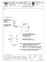
Control of primary heat is abnormal;
high temperature overshoots or E01
error occurs intermittently.
Dirty thermocouple connections. Examine connection of thermocou-
ples to long green plug on heater
control board. Unplug and re-plug
thermocouple wires, cleaning off any
debris. Unplug and re-plug long
green connector.
Thermocouple not contacting heater
element.
Loosen ferrule nut (N), push in ther-
mocouple (310) so tip (T) contacts
heater element (307). Holding themo-
couple tip (T) against heater element,
tighten ferrule nut (N) 1/4 turn past
tight. See page 38 for illustration.
Failed heater element. See Primary Heaters, page 37.
Signal failure from thermocouple. See E04: Fluid Temperature Sen-
sor (FTS) or thermocouple discon-
nected, page 10.
Thermocouple wired incorrectly. See E04: Fluid Temperature Sen-
sor (FTS) or thermocouple discon-
nected, page 10. Power up zones
one at a time and verify that tempera-
ture for each zone rises.
A
B

Troubleshooting
312063S 19
Hose Heat System
Before performing any troubleshooting procedures:
1. Relieve pressure, page 27.
2. Turn main power OFF .
3. Allow equipment to cool.
Problems
Try the recommended solutions in the order given for
each problem, to avoid unnecessary repairs. Also,
determine that all circuit breakers, switches, and con-
trols are properly set and wiring is correct before assum-
ing there is a problem.
PROBLEM CAUSE SOLUTION
Hose heats but heats slower than usual
or it does not reach temperature.
Ambient temperature is too cold. Use auxiliary hose heat system.
FTS failed or not installed correctly. Check FTS, page 10.
Low supply voltage. Verify line voltage. Low line voltage sig-
nificantly reduces power available to
hose heat system, affecting longer
hose lengths.
Hose does not maintain temperature
while spraying.
A and B setpoints too low. Increase A and B setpoints. Hose is
designed to maintain temperature, not
to increase it.
Ambient temperature is too cold. Increase A and B setpoints to increase
fluid temperature and keep it steady.
Flow too high. Use smaller mix chamber. Decrease
pressure.
Hose was not fully preheated. Wait for hose to heat to correct tem-
perature before spraying.
Low supply voltage. Verify line voltage. Low line voltage sig-
nificantly reduces power available to
hose heat system, affecting longer
hose lengths.
Hose temperature exceeds setpoint.
A and/or B heaters are overheating
material.
Check primary heaters for either a ther-
mocouple problem or a failed element
attached to thermocouple, page 10.
Faulty thermocouple connections. Verify that all FTS connections are
snug and that pins of connectors are
clean. Examine connection of thermo-
couples to long green plug on heater
control board. Unplug and re-plug ther-
mocouple wires, cleaning off any
debris. Unplug and re-plug long green
connector on heater control board.
Missing or damaged insulation around
FTS, causing the hose heat to be ON
constantly.
Make sure the hose bundle has ade-
quate insulation evenly covering the
entire length and connection joints.

Troubleshooting
20 312063S
Erratic hose temperature.
Faulty thermocouple connections. Verify that all FTS connections are
snug and that pins of connectors are
clean. Examine connection of thermo-
couples to long green plug on heater
control board. Unplug and re-plug ther-
mocouple wires, cleaning off any
debris. Unplug and re-plug long green
connector.
FTS not installed correctly. FTS should be installed close to end of
hose in same environment as gun. Ver-
ify FTS installation, page 40.
Missing or damaged insulation around
FTS, causing the hose heat to be ON
constantly.
Make sure the hose bundle has ade-
quate insulation evenly covering the
entire length and connection joints.
Hose does not heat.
FTS failed or is not contacting
correctly.
Check FTS, page 40.
FTS not installed correctly. FTS should be installed close to end of
hose in same environment as gun. Ver-
ify FTS installation, page 40.
Temperature control alarm. Check temperature display or diagnos-
tic code, page 40.
Hoses near Reactor are warm, but
hoses downstream are cold.
Shorted connection or failed hose heat-
ing element.
With hose heat on and temperature
setpoint above displayed hose zone
temperature, verify voltage between
connectors at each section of hose.
Voltage should drop incrementally for
each section of hose further from Reac-
tor. Use safety precautions when hose
heat is turned on.
PROBLEM CAUSE SOLUTION
/