
Right choice for ultimate yield
LSIS strives to maximize customers' profit in gratitude of choosing us for your partner.
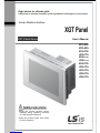
Human Machine Interface
XGT Panel
User’s Manual
Read this manual carefully before
installing,
wiring, operating, servicing
or inspecting this equipment.
Keep this manual within easy reach
for quick reference.
XGT Panel Series
http://eng.lsis.biz
XP30-
BTE
XP30-
BTA
XP30-
TTE
XP30-TT
A
XP40-
TTE
XP40-
TTA
XP50-
TTE
XP50-
TTA
XP70-
TTA
XP80-
TTA
XP90-
TTA

Safety Precautions
1
Before using the product…
To use the product safely and effectively, please read this instruction manual thoroughly before use.
► Please keep to the safety precaution, for it is to prevent accidents and potential danger from
occurring.
► Safety precaution is classified into ‘Warning’ and ‘Caution’ and their meanings are as follows.
Violating the instruction may result in serious personal injury or death.
Violating the instruction may result in slight personal injury or product
damage.
► The indicated illustrations on the product and in the manual have the following meanings.
Be cautious, for danger may be present.
Be cautious, for there is a possibility of an electric shock.
► After reading the instruction manual, keep it handy for quick reference.
Warning
Caution

Safety Precautions
2
Design Precautions
Design Precautions
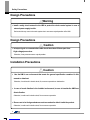
Installation Precautions
Install a safety circuit external to the HMI to protect the whole control system in case of
external power supply trouble.
Serious trouble may occur to the entire system due to erroneous output/operation of the HMI.
Warning
In/output signal or communication cable should be at least 100mm apart from
High-voltage/power wires.
Otherwise, it may cause erroneous output/operation.
Use the HMI in an environment that meets the general specification contained in this
manual or datasheet.
Otherwise, it could result in electric shock, fire, erroneous operation or deterioration.
In case of much vibration in the installed environment, be sure to insulate the HMI from
direct vibration.
Otherwise, it could result in electric shock, fire or erroneous operation.
Be sure not to let foreign substances such as conductive debris inside the product.
Otherwise, it could result in electric shock, fire or erroneous operation.
Caution
Caution

Safety Precautions
3
Wiring Precautions
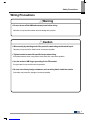
Be sure to turn off the HMI and external power before wiring.
Otherwise, it may result in an electric shock or damage to the product.
Wire correctly by checking each of the product’s rated voltage and terminal layout.
Otherwise, it may result in fire, electric shock or erroneous operation.
Tighten terminal screws with specified torque when wiring.
If terminal screws are loose, it may result in short circuits, fire or erroneous operation.
Use the exclusive HMI 3-type grounding for the FG terminal.
If not grounded, it may result in erroneous operation.
Be sure not to let any foreign substances such as wiring debris inside the module.
Such debris may cause fire, damage or erroneous operation.
Cautio
n
Warning

Safety Precautions
4
Startup and Maintenance Precautions
Disposal Precaution
Do not touch the terminals while power is on.
Otherwise, it may cause electric shock or erroneous operation.
Turn off the PLC and external power when cleaning or tightening the terminal.
Otherwise, it may cause electric shock or erroneous operation.
Do not charge, disassemble, heat, short circuit, solder, etc. the battery.
Mishandling the battery may cause overheating, crack, fire and may result in injury or fire.
Do not disassemble PCB from the product case or modify the product.
Otherwise, it may result in fire, electric shock or erroneous operation.
Use cellular phone or walky-talky at least 30cm away from the PLC.
Otherwise, it may result in erroneous operation.
When disposing of this product or battery, treat it as industrial waste.
Otherwise, it may cause poisonous pollution or explosion.
Warning
Caution
Caution

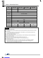
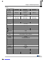
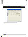
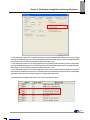
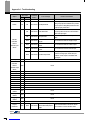
Revision History
Revision History
Version Date Contents Revised location
V1.0 ‘07.4 First Edition -
V2.0 ’09.10 1. Initial screen changed (horizontal bar -> square box type)
2. Menu name of initial screen changed
(Download From USB -> Storage Download)
3. Selecting one project file among many project files is available
4. Sending project file by CF card is available
5. File backup function by external storage equipment added
6. Format of backup file is changed into CSV format
7. New module XP80-TTA/AC added
8. Project upload function by external storage equipment added
9. Update function by external storage equipment added
10. XP30-BTE interface added
11. Figure and name of each part for XP30-BTE added
12. Specification of XP30-BTE added
13. Aux diagnosis function added
14. Dimension of XP30-BTE added
15. Specification of XP90-TTA/AC, XP70/80-TTA/DC added
16. Dimension of XP90-TTA/AC, XP70/80-TTA/DC added
17. PLC communication setting option in device menu added
18. Multi-Touch function in environment setting added
CH4, CH5, CH6, CH8
CH7.1
CH7
CH7
CH9
CH9
CH3, CH12, APP2
CH7
CH7
CH1
CH2
CH3
CH5
APP2
CH3, CH10
APP2
CH6.7
CH4.1
V2.1 ’10.06 1. XP30-TTE/DC added
2. Clear Data function in Environment Setting added
CH2.1, CH3.2, CH10
CH4.7
V2.2 ’11. 06 1. XP50-TTE/DC added
CH2.1, CH3.2, CH10
V2.3 ’12. 06 1. XP40-TTE(TTA)/DC added
2. Important User Information added
(about protection sheet and using ferrite core)
3. CE Standard Certification updated
CH2,CH3.2,CH5,CH10
CH10.1, CH10.2
CH12.1
The number of User’s manual is indicated the right side of the back cover.
LS Industrial Systems Co., Ltd 2006 All Rights Reserved.

Contents
8
Chapter. 1 General Introduction ..................................................................................... 1-1~1-6
1.1 Usage of User Manual ................................................................................................................................................. 1-1
1.2 Feature .......................................................................................................................................................................... 1-2
1.3 Terminology ................................................................................................................................................................... 1-6
Chapter. 2 System Configuration ..................................................................................... 2-1~2-6
2.1 Name and Function of Each Part ................................................................................................................................ 2-1
2.2 System Configuration ................................................................................................................................................... 2-5
Chapter. 3 Standard Specification ................................................................................. 3-1~3-7
3.1 General Standards ........................................................................................................................................................ 3-1
3.2 Function Standards ....................................................................................................................................................... 3-3
Chapter. 4 System Configuration .................................................................................. 4-1~4-6
4.1 Touch Calibration .......................................................................................................................................................... 4-1
4.2 Backlight Setting ........................................................................................................................................................... 4-2
4.3 Date Time Setting ......................................................................................................................................................... 4-3
4.4 PC Connection Setting ................................................................................................................................................. 4-3
4.5 Ethernet Setting ............................................................................................................................................................ 4-4
4.6 Contrast Setting (only for XP30-BTA/DC) ................................................................................................................... 4-5
4.7 Environment Setting ..................................................................................................................................................... 4-5
Chapter. 5 Diagnostics .................................................................................................... 5-1~5-6
5.1 Screen Diagnosis ......................................................................................................................................................... 5-1
5.2 Touch Diagnosis ........................................................................................................................................................... 5-2
5.3 Backup Memory Diagnosis .......................................................................................................................................... 5-2
5.4 Flash Memory Diagnosis Function .............................................................................................................................. 5-3
5.5 CF Card Diagnosis ....................................................................................................................................................... 5-3
5.6 Serial Communication Diagnosis ................................................................................................................................. 5-4
5.7 LED Diagnosis .............................................................................................................................................................. 5-6
5.8 Aux Diagnosis ............................................................................................................................................................... 5-6
Chapter. 6 Viewing Information of PLC Connection Status ..................................... 6-1~6-8

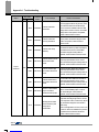
Contents
9
6.1 Connection Information ................................................................................................................................................ 6-2
6.2 PLC Information ............................................................................................................................................................ 6-3
6.3 History of PLC Error .................................................................................................................................................... 6-4
6.4 History of PLC Mode Conversion .............................................................................................................................. 6-5
6.5 History of PLC Power ................................................................................................................................................. 6-6
6.6 History of PLC System ............................................................................................................................................... 6-7
6.7 PLC Communication Configuration Settings ............................................................................................................ 6-8
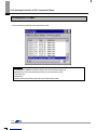
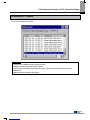
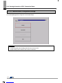
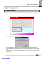
Chapter. 7 Storage Function................................................................................................... 7-3
7.1 General Introduction ................................................................................................................................................... 7-1
7.2 Downloading Project through the Storage Equipment ............................................................................................... 7-2
7.3 Uploading Project through the Storage Equipment .................................................................................................... 7-2
7.4 Updating the Device through Storage Equipment ...................................................................................................... 7-3
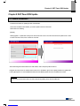
Chapter. 8 XGT Panel S/W Update ......................................................................................... 8-1
8.1 General Introduction ................................................................................................................................................... 8-1
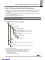
Chapter. 9 File Backup through External Storage Equipment .......................................... 9-5
9.1 Path Structure in case of File Backup .......................................................................................................................... 9-1
9.2 Operation setting when there is no Space for Backup ................................................................................................ 9-3
9.3 Monitoring Connection Status of External Storage Equipment .................................................................................. 9-4
Chapter. 10 Installation and Wiring .......................................................................... 10-1~10-10
10.1 Installation ................................................................................................................................................................. 10-1
10.1.1 Installation environment ................................................................................................................................. 10-1
10.1.2 Notice in handling ........................................................................................................................................... 10-2
10.1.3 Notice in installing the panel .......................................................................................................................... 10-2
10.2 Wiring ........................................................................................................................................................................ 10-6
10.2.1 Power wiring ................................................................................................................................................... 10-6
10.2.2 Ground wiring ............................................................................................................................................... 10-10
Chapter. 11 Maintenance ............................................................................................. 11-1~11-3
11.1 Maintenance............................................................................................................................................................... 11-1
11.2 Daily Maintenance ..................................................................................................................................................... 11-1
11.3 Periodical Maintenance ............................................................................................................................................. 11-2

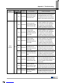
Contents
10
Chapter. 12 EMC Standard Certification ................................................................. 12-1~12-2
12.1 Requirement for EMC Standard Certification ........................................................................................................ 12-1
12.1.1 CE standard certification .............................................................................................................................. 12-1
12.1.2 MIC standard certification ............................................................................................................................ 12-2
12.2 Requirement for Low Voltage Command Suitability ............................................................................................... 12-2
12.2.1 Standard applied for XGT Panel ................................................................................................................... 12-2
12.2.2 Selection of XGT Panel ............................................................................................................................... 12-2
Appendix 1. Troubleshooting ..................................................... Appendix1-1~Appendix1-18
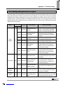
1. Type of Problem .............................................................................................................................................. Appendix 1-1
2. Problem when Starting ................................................................................................................................... Appendix 1-1
3. Reaction Problem when touching .................................................................................................................. Appendix 1-2
4. Display Problem of Figure and Object ........................................................................................................... Appendix 1-2
5. Communication Problem ................................................................................................................................ Appendix 1-5
6. CF/USB Removal of Memory Card ............................................................................................................... Appendix 1-6
7. Error Message during Execution of Program ................................................................................................ Appendix 1-7
Appendix 2. Dimension ............................................................... Appendix 2-1~ Appendix 2-4

Chapter 1. General Introduction
1-1
Chapter 1. General Introduction
1.1 Usage of User Manual
This manual provides information of each product’s specification, usage and so on. This is necessary to use XGT Panel for medium
and large HMI system.
The user manual’s configuration is as follows.
Sequence Category Contents
Chapter 1 General Introduction It describes this manual’s configuration, product’s feature and term.
Chapter 2 System Configuration It describes feature and system configuration of each XGT Panel.
Chapter 3 Standard Specification It describes XGT Panel’s general and function specification.
Chapter 4 System Configuration It describes XGT Panel’s system configuration.
Chapter 5 Diagnostics It describes XGT Panel’s self-diagnosis.
Chapter 6 Viewing information of
PLC Connection Status
It describes the way on connection status information of PLC which is
connected with XGT Panel.
Chapter 7 Transmission of Project
from USB Storage Device
It describes the way to execute the project by using USB storage device.
Chapter 8 XGT Panel S/W Update It describes the way to update engine at XGT Panel.
Chapter 9 Backup files by using
Storage Devices
It describes the way to backup recipe, logging and etc. files by using
storage devices.
Chapter 10 Installation and Wiring It describes an installation, wiring and caution for reliability of PLC system.
Chapter 11 Maintenance It describes inspection category and method for long normal operation of PLC
system.
Chapter 12 EMC Standard It describes system configuration for EMC standard.
Appendix 1
Troubleshooting It describes a variety of error contents and measure.
Appendix 2
Dimension It describes the dimension of XGT Panel.
Appendix 3
Warranty and
Environment Policy -
Remark
This manual doesn’t describe connection with XP-Builder and PLC. For their own function, Please refer to the related
manuals.

Chapter 1. General Introduction
1-2
1.2 Feature
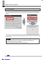
XGT Panel has the following features.
(1)
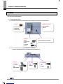
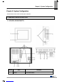
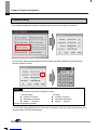
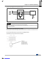
Diverse external interface
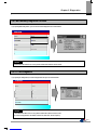
(a) It maximizes custom’s use by providing diverse external interface including USB, CF card and Ethernet.
(b) It can be connected with control device such as PLC, INVERTER.
• It can be connected by RS-232C, RS-422/485, Ethernet (10/100 BASE-T).
Ethernet
Open network
• Inverter
•
Inverter
CF card
Memory Interface
Logging data
Image/font data
Expansion connector
USB host
E
tc.
Tool port (RS
-
232C): XP
-
Builder
Printer
USB Storage
Device
Keyboard,
Mouse
Communication
Module

Chapter 1. General Introduction
1-3
(c) XP30-BTE(TTE), economic type, is not supported for Ethernet, expansion connector and CF card.
(2)
Based on Windows CE
(a) Adoption of Microsoft Company’s Windows CE
• Windows CE 5.0
(b) Advantage
• It provides stable software capacity by using Microsoft Company’s platform.
• It can process diverse function simultaneously.
• It provides diverse interface including Ethernet, USB, and CF card.
• The user interface including mouse and keyboard can be connected.
• It has high flexibility like computer software.
• Fast reaction is available when adding new equipment.
• Wide data sharing and management with upper system is available. (Later)
(3)
Improvement of project transmission time
(a) It provides Ethernet which is faster than RS-232C.
(b) It provides the transmission function from USB storage device.
(4)
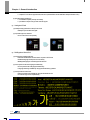
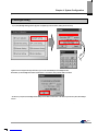
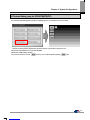
High quality screen
(a) It provides the high quality screen and clearness by high quality LCD.
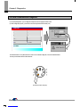
Download
Upload
Data change
RS232C
RS422/RS485
Terminal Block Type
Battery Cover
USB Port

Chapter 1. General Introduction
1-4
• It adopts TFT LCD which supports the 65,536 colors. (XP30-BTE/DC and XP30-BTA/DC adopts STN Mono LCD.)
(b) It provides diverse graphic type.
• It is available to express precisely and actually.
• It provides the simple moving function with GIF support.
(5)
Analog touch Panel
(a) It adopts analog (resistor film method) Touch Panel.
• Visibility is improved without the grids.
(b) It provides high touch resolution.
• It can control Touch Panel precisely.
(6)
Multilingual and diverse font
(a) It supports the multilingual function.
• It transmits the Windows/User font used in computer to XGT Panel.
• Additional language development is not necessary.
• Multilingual language is an advantage of Windows CE.
(b) It can express four kinds of language simultaneously.
• It can express 8 kinds of language simultaneously.
• Language switching is available by using special switch during operation.
(c) It can provide the various fonts.
• Various expressions are available by using the Windows/User font.
• Font size and type can be adjusted freely.

Chapter 1. General Introduction
1-5
(7)
Advanced function
(a) Alarm function
• The History alarm can be classified alarm group and alarm list and selected alarm can be expressed by alarm search.
• The Flow alarm indicates current or the latest alarm at the bottom of screen.
• The System alarm indicates the important problems from operation.
(b) Logging function
• It provides conditional logging according to device condition and continuous periodic logging which operates periodically
according to time and device status.
• It provides 255Kbyte areas for backup.
• Backup into CF card or USB storage device is available.
• Backup data’s type is stored in Excel, it is easy to use.
(c) Recipe function
• It provides READ/WRITE function.
• A recipe provides Max. 100 DWORDs and 16 blocks.
• Backup into the CF card or USB storage device is available.
• Backup data’s type is stored in Excel, it is easy to use.
(d) Scheduler function
• It can be set up to Max. 32.
(e) Print function
• It provides a Screen/Alarm print function.
• It can be printed by USB printer.
(f) Script function
• It provides more flexible function by user Script.
• It can be diversely applied to such as including Global/Object/Screen indication and so on.
(8)
Stable product suitable for international standards
(a)
CE, KC standard acquisition
(b) UL(cUL) standard acquisition

Chapter 1. General Introduction
1-6
1.3 Terminology
It describes terms used in this manual.
Term Definition Example
Module
A standard element that has a specified function which configures the system.
Devices such as I/O board, which inserted onto the mother board or base unit.
Ex.) CPU module
Power module,
I/O module
Unit
A single module or group of modules that perform an independent
operation as a part of PLC system.
Ex.) Basic unit,
Extension unit
PLC system
System consisted of PLC and peripheral device which can be controlled by
user program. -
XP-Builder Software used to write and edit the project. -
Cnet module
Computer Link
-
FEnet module Fast Ethernet Network -
RTC Abbreviation of ‘Real Time Clock’. It is used to call general IC that contains
clock function. -

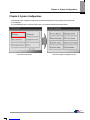
Chapter 2. System Configuration
2-1
Chapter 2. System Configuration
Here describes the feature of XGT Panel and system configuration.
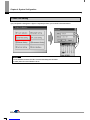
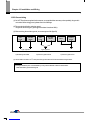
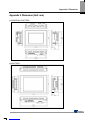
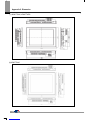
2.1 Name and Function of Each Part
1.
1. 1.
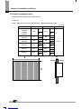
1. XP30-BTA, XP30/50/70/80-TTA
Number
Name Description
Front view 1) Analog touch panel: User touch input
2) LCD: screen indication

Chapter 2. System Configuration
2-2
Number
Name Description
LED Status
Indicates operation status of device
Green
Normal RUN status
(monitoring, downloading the project data)
Initializing the status when booting
(HMI does not operate)
Red Error occurs
(communication error, project data error)
Panel fixed part XGT Panel is fixed at panel by bracket.
CF card interface 1) Logging/recipe/screen data backup
2) Upgrade of windows CE is available.
Power connection terminal It consists of power input and FG terminal.
USB interface
It consists of 2 ports.
1) USB memory connection: logging/recipe/screen data backup
2) USB memory connection: project data transmission/backup
3) User interface connection: use of mouse/keyboard
4) Printer connection: printing is available
Extension port Extension module installation
Reset switch Hardware reset switch
TOOL interface
RS-232C interface
1) project data transmission
2) logging/recipe/alarm/screen data backup
3) machine software upgrade
Setting switch
Device setting switch
No.1 Reserved
No.2
A setting
Normal operation (default)
B setting
When upgrading Windows CE
No.3
A setting
Watchdog On (default)
B setting
Watchdog Off
No.4
A setting
RS-422/485 Terminal Switch On (120Ω)
B setting
RS-422/485 Terminal Switch Off (120Ω)
Extension module fixation hall Extension module fixation hall
RS-422/485 connector RS-422/485: PLC/control machine communication
RS-232C connector RS-232C: PLC/control machine communication
Ethernet terminal
Ethernet: 10Base-T / 100Base-TX
1) Project data transmission
2) logging/recipe/alarm/screen data backup
3) machine software upgrade
4) PLC/control machine communication
FG terminal FG terminal hole for extension module
Remark
(1) For details about communication connection, please refer to the communication user manual.
(2) For details about installation, please refer to the Chapter 10

Chapter 2. System Configuration
2-3
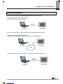
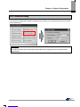
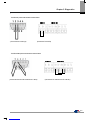
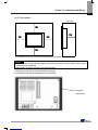
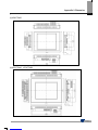
When you use the XGT Panel, the prevention tape is installed to prevent battery discharge.
If you remove this prevention tape, backup is available.
In order to remove tape, pull tape downward like the following figure.
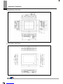
2. XP30-BTE, XP30-TTE, XP50-TTE, XP40-TTA(TTE)
Prevention
tape

Chapter 2. System Configuration
2-4
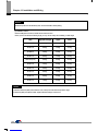
Number Name Description
Front view 1) Analog touch panel: User touch input
2) LCD: screen display
LED Status
Indicates operation status of module.
Green
Normal RUN status
(monitoring, downloading the project data)
Initializing mode when booting
(HMI does not Ready)
Red Error occurs
(communication error, project data error)
Panel fixed part XGT Panel is fixed at panel by bracket.
Power terminal
cover Prevention from electric shock
USB interface
1) USB memory connection: logging/recipe/screen data backup
2) USB memory connection: project data transmission/backup
3) User interface connection: use of mouse/keyboard
4) Printer connection: printing is available
Communication
interface RS-232C, RS-422/485: For communication with controller (PLC)
Reset switch Hardware reset switch
Battery cover Open or close when replacing the battery
Tool interface
RS-232C interface
1) Project data transmission
2) Logging/recipe/alarm/screen data backup
3) Machine software upgrade
Setting switch
Module setting switch
No.1 Reserved
No.2
A setting
Normal operation (default)
B setting
When upgrading Windows CE
No.3
A setting
Watchdog On (default)
B setting
Watchdog Off
No.4
A setting
RS-422/485 Terminal Switch On (120Ω)
B setting
RS-422/485 Terminal Switch Off (120Ω)
Power terminal It consists of power input and FG terminal
Ethernet terminal
Ethernet: 10Base-T / 100Base-TX
1) Project data transmission
2) logging/recipe/alarm/screen data backup
3) machine software upgrade
4) PLC/control machine communication
Supported on XP40-TTA

Chapter 2. System Configuration
2-5
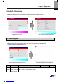
2.2 System Configuration
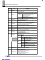
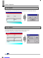
In order to use XGT Panel, write project data at the XP-Builder and transmit it to the XGT Panel.
XGT Panel can be basically connected through RS-232C.
Maximum communication speed is 115,200 [bps].
RS-232C communication speed is not fast so it takes long time to transmit project data into XGT Panel.
Project data can be quickly transmitted through Ethernet.
When LAN system is configured like the following figure, you can use it easily and effectively.
In case that LAN system is not configured, it provides 1:1 connection. (LAN cable should be cross cable.)
LAN
Ethernet
Page is loading ...
Page is loading ...
Page is loading ...
Page is loading ...
Page is loading ...
Page is loading ...
Page is loading ...
Page is loading ...
Page is loading ...
Page is loading ...
Page is loading ...
Page is loading ...
Page is loading ...
Page is loading ...
Page is loading ...
Page is loading ...
Page is loading ...
Page is loading ...
Page is loading ...
Page is loading ...
Page is loading ...
Page is loading ...
Page is loading ...
Page is loading ...
Page is loading ...
Page is loading ...
Page is loading ...
Page is loading ...
Page is loading ...
Page is loading ...
Page is loading ...
Page is loading ...
Page is loading ...
Page is loading ...
Page is loading ...
Page is loading ...
Page is loading ...
Page is loading ...
Page is loading ...
Page is loading ...
Page is loading ...
Page is loading ...
Page is loading ...
Page is loading ...
Page is loading ...
Page is loading ...
Page is loading ...
Page is loading ...
Page is loading ...
Page is loading ...
Page is loading ...
Page is loading ...
Page is loading ...
Page is loading ...
Page is loading ...
Page is loading ...
Page is loading ...
Page is loading ...
Page is loading ...
Page is loading ...
Page is loading ...
Page is loading ...
Page is loading ...
Page is loading ...
Page is loading ...
Page is loading ...
Page is loading ...
Page is loading ...
Page is loading ...
Page is loading ...
Page is loading ...
Page is loading ...
Page is loading ...
Page is loading ...
Page is loading ...
Page is loading ...
Page is loading ...
Page is loading ...
Page is loading ...
-
 1
1
-
 2
2
-
 3
3
-
 4
4
-
 5
5
-
 6
6
-
 7
7
-
 8
8
-
 9
9
-
 10
10
-
 11
11
-
 12
12
-
 13
13
-
 14
14
-
 15
15
-
 16
16
-
 17
17
-
 18
18
-
 19
19
-
 20
20
-
 21
21
-
 22
22
-
 23
23
-
 24
24
-
 25
25
-
 26
26
-
 27
27
-
 28
28
-
 29
29
-
 30
30
-
 31
31
-
 32
32
-
 33
33
-
 34
34
-
 35
35
-
 36
36
-
 37
37
-
 38
38
-
 39
39
-
 40
40
-
 41
41
-
 42
42
-
 43
43
-
 44
44
-
 45
45
-
 46
46
-
 47
47
-
 48
48
-
 49
49
-
 50
50
-
 51
51
-
 52
52
-
 53
53
-
 54
54
-
 55
55
-
 56
56
-
 57
57
-
 58
58
-
 59
59
-
 60
60
-
 61
61
-
 62
62
-
 63
63
-
 64
64
-
 65
65
-
 66
66
-
 67
67
-
 68
68
-
 69
69
-
 70
70
-
 71
71
-
 72
72
-
 73
73
-
 74
74
-
 75
75
-
 76
76
-
 77
77
-
 78
78
-
 79
79
-
 80
80
-
 81
81
-
 82
82
-
 83
83
-
 84
84
-
 85
85
-
 86
86
-
 87
87
-
 88
88
-
 89
89
-
 90
90
-
 91
91
-
 92
92
-
 93
93
-
 94
94
-
 95
95
-
 96
96
-
 97
97
-
 98
98
-
 99
99


LSIS XP90-TTA User manual
- Type
- User manual
Ask a question and I''ll find the answer in the document
Finding information in a document is now easier with AI
Other documents
-
POWER ACCESSORIES PB003 User manual
-
Pecron S1000 User manual
-
Omron NB Series Programmable Terminals Host User guide
-
-
Pro-face GP4000 SERIES Replacement Manualbook
-
Maxon XPO Datasheet
-
LS XGI-CPUU User manual
-
 Profile Design HSF Aerodrink BTA Tilt Bracket Operating instructions
-
-
Sanyo PLC-XP30 User manual
