Part number 550-141-589/0501
Front Section Repair Kit
Part Number 382-200-300 for Series 1 & 2
Part Number 382-200-300 for Series 3 & 4
GV BOILERGV BOILER
GV BOILERGV BOILER
GV BOILER
Replacement InstructionsReplacement Instructions
Replacement InstructionsReplacement Instructions
Replacement Instructions
Failure to follow items below can cause severe personal injury, death or substantial property damage:
These instructions are for use by a qualified installer/service technician. Follow all instructions in proper order.
Shut off main gas valve and disconnect electricity to boiler.
Wait until boiler is cooled down before proceeding with replacement.
WARNING Indicates presence of hazard which
can cause severe personal injury,
death or substantial property damage.
WARNING
The following terms are used in these instructions to bring attention to presence of hazards of various risk levels, or to important
information concerning the life of the product.
Ignitor Replacement Kit
Studs, nuts, washers, adapters, flange gaskets pump/
return water tubing
Square cut seals, silicone sealant
Instructions
Instructions for blower motor/replacement
Contents of Kit:
CAUTION Indicates presence of hazard which will
or can cause minor personal injury or
property damage.
1. Remove jacket top and front panels. Lay aside boiler
insulation.
2. Close isolation valves between boiler and system.
Drain boiler.
3. Remove:
All wiring connectors from control tray.
Control tray (if applicable).
External system gas and water piping from boiler.
Thermostat wiring.
External vent piping.
External combustion air piping, if used.
Vent condensate drain hose.
Blower assembly and burner. See “Blower Assembly
or Burner Replacement Instructions,” part number
550-141-608, packed with kit.
High limit control and well.
External relief valve piping.
External air vent piping (if used).
Remaining outside and interior jacket panels.
Block temperature limit switch.
Circulator(s).
4. Tilt block assembly onto back section to rest on 2
short pieces of 2 x 4’s.
5. Remove drain valve and all other remaining piping on
front section.
6. Remove vent ell and clean silicone sealant from vent
ell (Series 1 & 2 only).
CAUTION Do not use any cleaner containing
petroleum-based distillate (oil). Square
cut seal failure will occur.
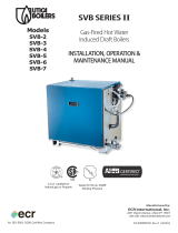
11. Apply bead of silicone sealant around perimeter of
intermediate section, NOT on inside of waterway holes
(see Figure 1).
Figure 1
Silicone
Sealant
12. Insert new square cut seals.
13. Align front section and lay it on top of intermediate
section.
7. Remove base rail assembly and tie rods from block
assembly.
8. Remove front section from block and remove
silicone sealant from mating intermediate section.
9. Clean new front section and mating intermediate
section of any oil and dirt - silicone sealant will not
adhere properly.
10. Clean square cut sealing surfaces on new and
mating sections.
Do Not
Apply
Silicone
Sealant
Here
Do Not
Apply
Silicone
Sealant
Here
CAUTION Section block is heavy - care must be
taken in moving to avoid personal
injury.