Page is loading ...

Owner’s Manual
HTS “Wn” Type
Automatic
Transfer Switch
600 through 2600 Amp,
600 Volts
This manual should remain with the unit.

Generac cannot anticipate every possible circumstance that might
involve a hazard. The warnings in this manual, and on tags and
decals affixed to the unit are, therefore, not all-inclusive. If using a
procedure, work method or operating technique the manufacturer
does not specifically recommend, ensure that it is safe for others.
Also make sure the procedure, work method or operating tech-
nique utilized does not render the transfer switch unsafe.
Throughout this publication, and on tags and decals affixed to the
generator, DANGER, WARNING, CAUTION and NOTE blocks are
used to alert personnel to special instructions about a particular
operation that may be hazardous if performed incorrectly or care-
lessly. Observe them carefully. Their definitions are as follows:
DANGER
After this heading, read instructions that, if not
strictly complied with, will result in serious per-
sonal injury, including death, or property damage.
After this heading, read instructions that, if not
strictly complied with, may result in personal injury
or property damage.
After this heading, read instructions that, if not
strictly complied with, could result in damage to
equipment and/or property.
NOTE:
After this heading, read explanatory statements that require
special emphasis.
These safety warnings cannot eliminate the hazards that they
indicate. Common sense and strict compliance with the special
instructions while performing the service are essential to prevent-
ing accidents.
Four commonly used safety symbols accompany the DANGER,
WARNING and CAUTION blocks. The type of information each
indicates follows:
This symbol points out important safety informa-
tion that, if not followed, could endanger personal
safety and/or property of others.
This symbol points out potential explosion hazard.
This symbol points out potential fire hazard.
This symbol points out potential electrical shock
hazard.
GENERAL HAZARDS
Any AC generator that is used for backup power if a NORMAL •
(UTILITY) power source failure occurs, must be isolated from
the NORMAL (UTILITY) power source by means of an approved
transfer switch. Failure to properly isolate the NORMAL and
STANDBY power sources from each other may result in injury
or death to electric utility workers, due to backfeed of electrical
energy.
Improper or unauthorized installation, operation, service or •
repair of the equipment is extremely dangerous and may result
in death, serious personal injury, or damage to equipment and/
or personal property.
Extremely high and dangerous power voltages are present inside •
an installed transfer switch. Any contact with high voltage ter-
minals, contacts or wires will result in extremely hazardous,
and possibly LETHAL, electric shock. DO NOT WORK ON THE
TRANSFER SWITCH UNTIL ALL POWER VOLTAGE SUPPLIES
TO THE SWITCH HAVE BEEN POSITIVELY TURNED OFF.
Competent, qualified personnel should install, operate and ser-•
vice this equipment. Adhere strictly to local, state and national
electrical and building codes. When using this equipment,
comply with regulations the National Electrical Code (NEC),
CSA Standard; C22.1 Canadian Electric Code and Occupational
Safety and Health Administration (OSHA) have established.
IMPORTANT SAFETY INSTRUCTIONS
Read the following information carefully before attempting to install, operate or service this equip-
ment. Also read the instructions and information on tags, decals, and labels that may be affixed to the
transfer switch. Replace any decal or label that is no longer legible.
DANGER! Connection of a generator to an electrical system normally supplied by an electric utility
shall be by means of suitable transfer equipment so as to isolate the electric system from utility dis-
tribution system when the generator is operating (Article 701 Legally Required Standby Systems or
Article 702 Optional Standby Systems, as applicable). Failure to isolate electric system by these
means may result in damage to generator and may result in injury or death to utility workers due to
backfeed of electrical energy.

Table of Contents
1
Safety Rules .................................. Inside Front Cover
Section 1 — General Information .............................. 2
1.1 Introduction ................................................................................2
1.2 Equipment Description ................................................................2
1.3 Transient Voltage Surge Suppression ..........................................2
1.4 Communications ........................................................................3
1.5 Operation with Loss of Communications .....................................3
1.6 Transfer Switch Data Label .........................................................3
1.7 Transfer Switch Enclosure ..........................................................3
1.8 Safe Use Of Transfer Switch .......................................................3
Section 2 — Installation ............................................. 4
2.1 Introduction to Installation ..........................................................4
2.2 Unpacking ..................................................................................4
2.3 Mounting ....................................................................................4
2.4 Connecting Power Source and Load Lines ..................................4
2.5 Connecting Controller Communication Wires ..............................5
2.6 Setting DIP Switches ..................................................................5
2.7 Programming .............................................................................6
2.8 Auxiliary Contacts ......................................................................6
Section 3 — Operation............................................... 7
3.1 Functional Tests & Adjustments ..................................................7
3.2 Manual Operation .......................................................................7
3.3 Voltage Checks ..........................................................................8
3.4 Electrical Operation.....................................................................9
3.5 Transfer Mechanism ...................................................................9
3.6 Transfer Mechanism Operation ...................................................9
3.7 Switches and Indicators .............................................................9
3.8 Sequence of Operation .............................................................10
3.9 Transfer Switch Options............................................................12
Section 4 – Maintenance.......................................... 13
4.1 Operate Transfer Switch ...........................................................13
4.2 Clean and Inspect Transfer Switch ............................................13
4.3 Lubrication ...............................................................................13
4.4 Main Current Carrying Contacts ................................................13
4.5 Batteries ...................................................................................13
Section 5 – Notes ..................................................... 14
Section 6 – Mounting Dimensions .......................... 16
Section 7 – Wiring Diagrams & Electrical
Schematics ........................................... 28
Section 8 – Exploded Views & Parts Lists .............. 36
Section 9 – Warranty .................................Back Cover
Never handle any kind of electrical device while standing •
in water, while barefoot, or while hands or feet are wet.
DANGEROUS ELECTRICAL SHOCK MAY RESULT.
Because jewelry conducts electricity, wearing it may cause •
dangerous electrical shock. Remove all jewelry (such as rings,
watches, bracelets, etc.) before working on this equipment.
If work must be done on this equipment while standing on metal •
or concrete, place insulative mats over a dry wood platform.
Work on this equipment only while standing on such insulative
mats.
Never work on this equipment while physically or mentally •
fatigued.
Keep the transfer switch enclosure door closed and bolted at all •
times. Only qualified personnel should be permitted access to
the switch interior.
In case of an accident caused by electric shock, immediately •
shut down the source of electrical power. If this is not possible,
attempt to free the victim from the live conductor but AVOID
DIRECT CONTACT WITH THE VICTIM. Use a nonconducting
implement, such as a rope or board, to free the victim from the
live conductor. If the victim is unconscious, apply first aid and
get immediate medical help.
When an automatic transfer switch is installed for a standby •
generator set, the generator engine may crank and start at
any time without warning. To avoid possible injury that might
be caused by such sudden start-ups, the system’s automatic
start circuit must be disabled before working on or around
the generator or transfer switch. For that purpose, a SAFETY
DISCONNECT is provided inside the transfer switch. Always
set that switch to its MANUAL position before working on the
equipment. Then place a “DO NOT OPERATE” tag on the trans-
fer switch and on the generator.

2
Section 1 — General Information
HTS “Wn” Type Transfer Switch
1.1 INTRODUCTION
This manual has been prepared especially for the purpose of famil-
iarizing personnel with the design, application, installation, opera-
tion and servicing of the applicable equipment. Read the manual
carefully and comply with all instructions. This will help to prevent
accidents or damage to equipment that might otherwise be caused
by carelessness, incorrect application, or improper procedures.
Every effort has been expended to make sure that the contents
of this manual are both accurate and current. The manufacturer
reserves the right to change, alter or otherwise improve the prod-
uct at any time without prior notice.
1.2 EQUIPMENT DESCRIPTION
The commercial transfer switch range (HTS) is designed to oper-
ate in conjunction with the Power Manager Gxxx and Hxxx series
of Generator controllers. The transfer switch has a simple 2-wire
communications link to the Generator controller and can thus be
mounted remote from the Generator.
Utility voltage is monitored by the HTS and fed back to the engine
generator control panel for comparison against setpoints, used to
determine if the Utility voltage is "good".
Operation of the switch is instigated by the generator control
panel, however, all aspects of TDN timing or inphase transfer are
handled locally at the HTS. The HTS monitors a single phase of the
Generator voltage in order to perform inphase transfers.
All timers and voltage setpoints are programmable in the G/H
control panel. Some of the decisions are made by the HTS itself
so the appropriate parameters are passed to the HTS via the com-
munication link. If the communication link were to break, the HTS
will still function. It will monitor the Utility and Generator voltages
and make the transfer determination itself, rather than being com-
manded by the generator control panel. It will either use the last
parameters sent, or, if no parameters were ever sent (communica-
tions were never established), it will take its settings from onboard
DIP Switches and a set of resident parameters.
The automatic transfer switch is used for transferring critical elec-
trical load from a NORMAL (UTILITY) power source to a STANDBY
(EMERGENCY) power source. Such a transfer of electrical loads
occurs automatically when the NORMAL power source has failed
or is substantially reduced and the STANDBY source voltage and
frequency have reached an acceptable level. The transfer switch
prevents electrical feedback between two different power sources
(such as the NORMAL and STANDBY sources) and, for that rea-
son, codes require it in all standby electric system installations.
1.3 TRANSIENT VOLTAGE SURGE
SUPPRESSION
The Transient Voltage Surge Suppression (TVSS) is provided to
protect the load from electrical surges and/or transient voltage
spikes. This device is physically located on the side wall of the
enclosure. It is electrically connected to the load side of the trans-
fer switch. A 30 amp circuit breaker is provided to disconnect the
TVSS from the transfer switch for maintenance or replacement.
The TVSS is made up of multiple solid state Metal Oxide Varistors
(MOV) connected in parallel for each mode of protection. These
devices are equipped with integrated short circuit and individual
component level fusing. They are self-resetting and fully auto-
matic.
1.3.1 MODES OF PROTECTION
The TVSS provides protection on all modes:
Single-phase (6) - L-L, L-N, L-N, L-G, L-G and N-G.•
Three-phase (10) - L-L, L-L, L-L, L-N, L-N, L-N, •
L-G, L-G, L-G and N-G.
1.3.2 RATINGS
Surge Capacity: 88 kA per mode.•
1.3.3 CERTIFICATION
The TVSS is UL recognized to the requirements of UL 1449 2nd
edition.
1.3.4 TVSS DISCONNECT
Each TVSS is provided with a disconnect. The disconnect is a 30
amp circuit breaker, 2-pole for single-phase and 3-pole for three-
phase. This is to allow replacement of the TVSS module without
interruption of the electrical supply to the load.
DANGER
REPLACEMENT OF THE TVSS MODULE WHILE
THE ATS IS ENERGIZED SHOULD ONLY BE
PERFORMED BY A QUALIFIED ELECTRICIAN.
BE SURE TO TURN ON TVSS DISCONNECT
CIRCUIT BREAKER WHEN THE PROCEDURE IS
COMPLETE. IF THE CIRCUIT BREAKER IS NOT
TURNED ON THE TVSS MODULE WILL NOT
PROVIDE ANY SURGE PROTECTION FOR THE
CUSTOMER LOAD.
1.3.5 STATUS INDICATORS
Each TVSS module has comprehensive, solid state, continual
visual status monitoring of each protection mode present. There
are two LED’s provided, located on the cover of the module. The
GREEN LED (left side) is used to indicate that the TVSS module is
energized and in working order. The RED LED (right side) will turn
on in the event the suppressor capability is exceeded or if there is
an internal safety component activating.
When the power is first applied, the unit does a brief internal diag-
nostic test. During this test, the RED LED will illuminate briefly, go
off and then the GREEN LED will illuminate.

3
Section 1 — General Information
HTS “Wn” Type Transfer Switch
For the power source to be available, the associated service dis-
connect circuit breaker must be ON, the associated TVSS discon-
nect circuit breaker must be ON and the associated source must
be present.
The LED status indicators can be viewed directly on the TVSS
module with the enclosure door open.
1.3.6 REMOTE ALARM CONTACTS
Each TVSS module is equipped with a set of alarm contacts to
indicate the TVSS module protection status, to a external alarm.
This is available as a full set of dry relay contacts (C, NO, NC).
The contact ratings are; 3A, 250Vdc or 230Vac maximum. The
contacts are wired to a three position terminal strip for customer
connection.
If the contacts change state, it indicates either a power failure to
the TVSS module or a failure of the TVSS module.
1.4 COMMUNICATIONS
The HTS acts as a Modbus slave on the communications network.
For the "H" series of generator controllers, Port 1 should be used
for a connection. On the "G" series of controllers, Port 0 should be
used. The base Modbus address for the transfer switch is set at
240 but can be modified using dip switches DIP1 - switches 7 and
8. Unless there are two transfer switches on the network, these
switches can be left in the OFF position.
Communications parameters on the Power Manager should be
set to:
Modbus Master Port•
4800 Baud•
No parity, 2 stop bits•
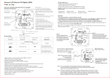
The Network uses Modbus RTU protocol. Communications are
sent at a one second rate. If no Good messages are received
within 20 seconds, the communications link is determined to be
bad and the switch controller will revert to local control. If the link
re-establishes itself the remote control from the H-panel restarts
(Figure 1.1).
Figure 1.1 - Typical Communication Network
H/G Panel
(Master)
PORT 1 (H) or 0 (G)
Remote
Annunciator
(Slave)
H Transfer
Switch
(Slave)
GenLink
via PC
RS485
Remote
Annunciator
(Slave)
1.5 OPERATION WITH LOSS OF
COMMUNICATIONS
Local control means that if the generator is running and there is no
utility, the switch will then transfer to the generator. If utility returns,
the switch will transfer back to utility. The generator will not start or
stop automatically as it cannot communicate with the switch and
does not know utility is missing. It will have to be manually started
and stopped (with the keyswitch set in the manual position).
1.6 TRANSFER SWITCH DATA
LABEL
A Data LABEL is permanently affixed to the transfer switch enclo-
sure. Use this transfer switch only with the specific limits shown
on the DATA LABEL and on other decals and labels that may be
affixed to the switch. This will prevent damage to equipment and
property.
When requesting information or ordering parts for this equipment,
make sure to include all information from the DATA LABEL.
Record the Model and Serial numbers in the space provided for
future reference.
MODEL #
SERIAL #
1.7 TRANSFER SWITCH
ENCLOSURE
The standard switch enclosure is a National Electrical Manufacturer’s
Association (NEMA) 12 type. NEMA 12 type enclosures primarily
provide protection against contact with the enclosed equipment
and provide a degree of protection against dust, falling dirt, and
dripping non-corrosive liquids. NEMA 12 type enclosures are for
indoor use only.
1.8 SAFE USE OF TRANSFER
SWITCH
Before installing, operating or servicing this equipment, read the
SAFETY RULES (inside front cover) carefully. Comply strictly
with all SAFETY RULES to prevent accidents and/or damage to
the equipment. The manufacturer recommends that a copy of the
SAFETY RULES be posted near the transfer switch. Also, be sure
to read all instructions and information found on tags, labels and
decals affixed to the equipment.
The publications that outline the safe use of transfer switches are
the following:
NFPA 70; National Electrical Code•
NFPA 70E; Standard for Electrical Safety in the Workplace•
UL 1008, STANDARD FOR SAFETY-AUTOMATIC TRANSFER •
SWITCHES

4
NOTE:
It is essential to use the latest version of any standard to ensure
correct and current information.
2.1 INTRODUCTION TO
INSTALLATION
This equipment has been wired and tested at the factory. Installing
the switch includes the following procedures:
Mounting the enclosure.•
Connecting power source and load leads.•
Connecting the generator communication circuit.•
Setting DIP switches on ATS controller.•
Programming Gxxx or Hxxx control on engine generator.•
Installing/connecting any options and accessories.•
Testing functions.•
2.2 UNPACKING
Carefully unpack the transfer switch. Inspect closely for any dam-
age that might have occurred during shipment. The purchaser
must file with the carrier any claims for loss or damage incurred
while in transit.
Check that all packing material is completely removed from the
switch prior to installation.
Attach any lifting device to the transfer switch mounting holes or
brackets only. DO NOT LIFT THE SWITCH AT ANY OTHER POINT.
2.3 MOUNTING
Mounting dimensions for the transfer switch enclosure are in this
manual. Enclosures are typically floor standing and mounted to
the wall. Components are generally mounted in a standard NEMA
12-type enclosure. A NEMA 3R, is also available. See TRANSFER
SWITCH OPTIONS section.
Handle transfer switches carefully when install-
ing. Do not drop the switch. Protect the switch
against impact at all times, and against con-
struction grit and metal chips. Never install a
transfer switch that has been damaged.
Install the transfer switch as close as possible to the electrical
loads that are to be connected to it. Stand the enclosure on a flat
surface. If the surface is not flat, it will be necessary to add shims
to make the enclosure level. Mount to a wall or support structure
for vertical stability. To prevent switch distortion, level all mounting
points. If necessary, use washers behind mounting holes to level
the unit.
2.4 CONNECTING POWER SOURCE
AND LOAD LINES
DANGER
Make sure to turn OFF both the NORMAL
(UTILITY) and STANDBY (EMERGENCY) power
supplies before trying to connect power source
and load lines to the transfer switch. Supply
voltages are extremely high and dangerous.
Contact with such high voltage power supply
lines causes extremely hazardous, possibly
lethal, electrical shock.
Wiring diagrams and electrical schematics are provided in this
manual. Power source and load connections are made at a transfer
mechanism, inside the switch enclosure.
2.4.1 TRANSFER MECHANISMS
The transfer mechanism may be either a 2-pole, 3-pole, or 4-pole
type (Figure 2.1). The switch enclosure may include a NEUTRAL
BLOCK for connection of the NEUTRAL line. Connect power source
and load leads to transfer mechanism terminal lugs as follows:
LOAD Leads: Connect to terminals T1, T2, T3, etc.•
NORMAL (• UTILITY) Source Leads: To terminals N1, N2, N3,
etc.
STANDBY (• EMERGENCY) Source Leads: Connect to transfer
mechanism terminal lugs E1, E2, E3, etc.
Figure 2.1 — Transfer Mechanism
U
TILIT
Y
A
ON
B
S
TANDB
Y
O
F
F
A1
A2
B1
B2
AT1
AT2
BT2
BT1
6
47
96
XXXXXX
600
VA
C
CSA
TRAN
S
FER
S
WIT
CH
RATED
CU
RREN
T
4
80
VA
C
UL
RATED V
O
LTA
GE
4
00
AM
P
06
27
0
7-T
06
27
0
7-T
06
27
0
7-T
062707-
T
062707-
T
062707-
T
062707-T
-T
062707-T
T
Section 2 — Installation
HTS “Wn” Type Transfer Switch

5
Section 2 — Installation
HTS “Wn” Type Transfer Switch
NOTE:
Unless otherwise specified, a NEUTRAL block is not supplied
with the transfer switch on single phase, 3-pole units where the
NEUTRAL line is to be switched during transfer action. Similarly,
a NEUTRAL block is not supplied on 3-phase, 4-pole units where
the NEUTRAL line is to be switched during transfer.
Solderless, screw-type terminal lugs are standard. Conductor
sizes must be adequate to handle the maximum current to which
they will be subjected. The installation must comply fully with all
applicable codes, standards and regulations.
Before connecting wiring cables to terminals, remove any surface
oxides from the cable ends with wire brush. If ALUMINUM conduc-
tors are used, apply joint compound. Tighten terminal lugs to the
torque values in the following chart.
SWITCH RATING WIRE SIZE TORQUE RATING
600 AMP 500MCM-1/0 375 INCH-LBS
800/1000 AMP 500MCM-1/0 375 INCH-LBS
1200/2600 AMP 750MCM-1/0 500 INCH-LBS
All power cables should enter the switch next to transfer mecha-
nism terminals. Standard terminal lugs on the transfer mechanism
are solderless, screw-type.
Be sure to maintain proper electrical clearance between live metal
parts and grounded metal. Allow at least one inch for circuits over
400 amps.
2.5 CONNECTING CONTROLLER
COMMUNICATION WIRES
Use shielded 2-wire communications cable (such as Belden
#9460) to make the communications line connection from the
HTS transfer switch to the engine generator connection panel.
This cable is to be routed in a separate conduit between the HTS
transfer switch and the engine generator. The cable is to be con-
nected as follows:
HTS transfer switch - 4 position terminal block, in the bottom of
the transfer switch enclosure (labeled "comm. Ports").
Engine generator - terminal strip in connection panel that houses
the circuit breaker. Do not connect the shield at this end.
2.6 SETTING DIP SWITCHES
The dip switches, in the HTS, are read once, only at power up. If
the communications to the Power Manager or the engine controller
are working, it will overwrite the dip switch settings. In this way
there are no conflicts and also the transfer switch will use the latest
settings even if the communications fail.
2.6.1 DIP SWITCH 1
Voltage Codes
THREE PHASE DIP SWITCH SELECTED
Code Dip1_3 2 1
0 = 480 Vac 0 0 0
1 = 600 Vac 0 0 1
2 = 415 Vac 0 1 0
3 = 240 Vac 0 1 1
4 = 220 Vac 1 0 0
5 = 208 Vac 1 0 1
6 = 480 Vac (spare) 1 1 0
7 = 480 Vac (spare) 1 1 1
All voltages listed, are Line - Line and all three phases are
checked.
SINGLE PHASE DIP SWITCH SELECTED
Code Dip1 3 2 1
0 = xxx vac 0 0 0
1 = xxx vac 0 0 1
2 = xxx vac 0 1 0
3 = 240 vac 0 1 1
4 = 220 vac 1 0 0 (usually 50Hz)
5 = xxx vac 1 0 1
6 = xxx vac 1 1 0
7 = xxx vac 1 1 1
All voltages are expressed as line - line, but checked as line - neu-
tral, line - neutral and line - line.
As of the V1.8 software release, there will only be one PCB for all
voltage codes.
TDN/INPHASE - Dip1- switch 4: Set this switch to ON to select •
TDN type transfers.
CTTS/OTTS - Dip1 - switch 5: Set this switch to OFF for a OTTS •
type transfer switch.
THREE PHASE - Dip1 - switch 6: Set this switch to ON for 3 •
phase wiring. Set this switch to OFF for single-phase wiring.
MODBUS ADDRESS - Dip1- switches 7,8: The base Modbus •
address for the transfer switch is set at 240. The transfer switch
will NOT respond to the universal address 250. By changing the
address dip switches, the full range of available addresses for
transfer switches is:
GenLink DCP
Modbus address Dip1 - 8 7 Switch Number
240 0 0 1
241 0 1 2
242 1 0 3
243 1 1 4

6
2.6.2 DIP SWITCH 2
60/50 Hz - Dip2 - switch 1: Set this switch to ON for a 60Hz •
system. This setting is only used if the communications fail.
Normally it will be overridden by the target frequency setting in
the G/H panel. The Generator and Utility must be within 1Hz of
this nominal frequency for an inphase transfer to take place.
2.6.3 SWITCHES 2 TO 6
These switches no longer have any function.
2.6.4 SWITCHES 7 AND 8
These switches select the communications baud rate, they are for
future development and should currently both be set to off (4800
baud).
Baud Rate Dip 8 7
4800 0 0
9600 0 1
38400 1 0 (V1.8)
57600 1 1 (V1.8)
2.6.5 SYNCHRONIZATION LIMITS
Synch requirements are:
Generator frequency within 1Hz of nominal•
Voltage within User Programmed limits•
Absolute Voltage difference within +/- 6V•
Generator/Utility Frequency difference within + 0.2/- 0.0 Hz•
Phase difference within - 7 / +0 degrees•
(i.e. Generator voltage is earlier than Utility and catching up, this
gives some compensation for the transfer switch closing delay).
2.6.6 VOLTAGE LIMITS
Determination of good Utility is done by the H or G controller
against user programmable limits. If the communication link to the
transfer switch breaks down, the following criteria are used for a
local determination.
Dropout — any phase outside - 70 to +130 % of nominal (not
the average voltage)
Pickup — all phases > +75 % of nominal
2.7 PROGRAMMING
The HTS transfer switch is controlled by the G/H control panel on
the engine generator. The timer, voltage pickup, dropout and exer-
cise settings are programmed into the G/H control panel. Please
refer to the G/H control panel manual for details on programming
the HTS transfer switch controls.
2.8 AUXILIARY CONTACTS
It is possible to add Auxiliary Contacts on the transfer switch to
operate customer accessories, remote advisory lights, or remote
annunciator devices. It is necessary to change the single pole limit
switch to a double pole device. Reconnect 0A, 147 and 148 to like
terminals on the double limit switch. A suitable power source must
be connected to the COMMON (C) terminal (Figure 2.3).
Contact operation is shown in the following chart:
Switch Position
Utility Standby
Common to Normally Open Closed Open
Common to Normally Closed Open Closed
NOTE:
Auxiliary Contacts are rated 10 amps at 125 or 250 volts AC.
DO NOT EXCEED THE RATED VOLTAGE AND CURRENT OF THE
CONTACTS.
Figure 2.3 — Auxiliary Contact Diagram
Section 2 — Installation
HTS “Wn” Type Transfer Switch

7
3.1 FUNCTIONAL TESTS AND
ADJUSTMENTS
Following transfer switch installation and interconnection, inspect
the entire installation carefully. A competent, qualified electrician
should inspect it. The installation should comply strictly with all
applicable codes, standards, and regulations. When absolutely
certain the installation is proper and correct, complete a functional
test of the system. Perform functional tests in the exact order pre-
sented in this manual, or the switch could be damaged.
IMPORTANT: Before proceeding with functional tests, read and
make sure all instructions and information in this section are
understood. Also read the information and instructions of labels
and decals affixed to the switch. Note any options or accessories
that might be installed and review their operation.
3.2 MANUAL OPERATION
DANGER
Do NOT manually transfer under load.
Disconnect transfer switch from all power sourc-
es by approved means, such as a main circuit
breaker(s).
A manual HANDLE is shipped with the transfer switch. Manual
operation must be checked BEFORE the transfer switch is operated
electrically. To check manual operation, proceed as follows:
1. In the transfer switch enclosure, set the Maintenance
Disconnect switch to MANUAL. This prevents the generator
from starting automatically as soon as the UTILITY power
source is turn OFF.
2. If so equipped, turn the generator’s AUTO/OFF/ MANUAL
switch to OFF.
3. Turn OFF both NORMAL and STANDBY power supplies to the
transfer switch, with whatever means provided (such as the
main line circuit breaker(s)).
4. Note position of transfer mechanism main contacts by
observing display windows in “A” and “B” in Figure 3.1 as
follows:
Window “A” ON, Window “B” OFF - LOAD terminals (T1, T2, •
T3) are connected to NORMAL terminals (N1, N2, N3).
Window “A” OFF, Window “B” ON - LOAD terminals (T1, T2, •
T3) are connected to STANDBY terminals (E1, E2, E3).
Do not use excessive force when operating the
transfer switch manually or the manual handle
could be damaged.
Section 3 — Operation
HTS “Wn” Type Transfer Switch
Figure 3.1 — Actuating Transfer Switch

8
3.2.1 CLOSE TO NORMAL SOURCE SIDE
Before proceeding, verify the position of the switch by observing
window “A” in Figure 3.1. If window “A” reads “ON”, proceed with
Step 1, and if it reads “OFF”, proceed with Step 2.
Step 1: With the handle attached to the actuating shaft, move •
handle in the direction of the arrow on the switch cover
until it stops — DO NOT FORCE. Release handle slowly
to allow the spring in the switch box to relax. “OFF” now
appears in Window “A” and “ON” appears in Window
“B”. (Proceed with Step 2).
Step 2: With the handle attached to the actuating shaft, move •
handle in the direction of the arrow on the switch cover
until it stops — DO NOT FORCE. Release handle slowly
to allow the spring in the switch box to relax. “ON” now
appears in Window “A” and “OFF” appears in Window
“B”. (Proceed with B: Close to STANDBY Source Side).
3.2.2 CLOSE TO STANDBY SOURCE SIDE
Before proceeding, ensure that the previous 3.2.1, “Step 2” Close
to NORMAL Source Side is completed. See Figure 3.1. This will
ensure that Window “B” on the switch reads “OFF”. With the
handle attached to the actuating shaft, move the handle in the
direction of the arrow on the switch cover until it stops - DO NOT
FORCE. Release handle slowly to allow the spring in the switch
box to relax. “OFF” now appears in Window “A” and “ON” appears
in Window “B”.
3.2.3 RETURN TO NORMAL SOURCE SIDE
Manually actuate switch to return Window “A” to the “ON” posi-
tion.
3.3 VOLTAGE CHECKS
DANGER
Disconnect all loads from the transfer switch
until all voltage checks and phase rotation
checks have been completed to prevent pos-
sible injury to personnel and, or damage to
equipment.
For safety, set the Maintenance Disconnect
switch (inside transfer switch enclosure) to its
MANUAL position before proceeding with volt-
age checks.
Before proceeding, check the transfer switch
data label for switch rated voltage. Make
sure the data label voltage is compatible with
NORMAL and STANDBY power source voltages.
Proceed with caution. Do not touch electrically
hot terminals, wires, etc. During the voltage
checks, the transfer switch is electrically ener-
gized.
Perform voltage checks as follows:
1. Inside the transfer switch enclosure, set the Maintenance
Disconnect switch to MANUAL.
2. If generator is so equipped, set the AUTO-OFF-MANUAL
switch to OFF.
3. Check that the word “ON” is visible in Window “A”, the word
“OFF” in Window “B”. See MANUAL OPERATION for location
of “A” and “B” windows.
IMPORTANT: DO NOT PROCEED UNTIL STEPS 1, 2, AND 3 HAVE
BEEN COMPLETED.
Before proceeding to voltage checks, manu-
ally connect the load to NORMAL power supply.
Window “A” must indicate ON, Window “B” must
indicate OFF before proceeding.
4. Locate the battery disconnect connector on the outside of the
transfer switch controller. Plug the two connectors together.
NOTE:
If BOTH UTILITY and GENERATOR sources are unavailable for
more than 24 hours, disconnect battery by unplugging battery
disconnect leads.
5. Turn ON the NORMAL (UTILITY) power supply to the transfer
switch, with whatever means provided (such as the main line
circuit breaker).
DANGER
The transfer switch is now electrically hot.
Proceed with caution.
6. With UTILITY voltage available to the transfer switch, check
that the SWITCH - POSITION UTILITY LED on the enclosure
door is ON. If the SWITCH - POSITION UTILITY LED is OFF,
turn off the utility power supply to the transfer switch by what-
ever means provided (such as the main line circuit breaker),
then proceed back to Step 1 of “VOLTAGE CHECKS”.
7. On the enclosure door, check that the UTILITY AVAILABLE
LED is ON.
8. With an accurate AC voltmeter, check the phase-to-phase (line-
to-line) and phase-to-neutral (line-to-neutral) voltages present
at transfer mechanism terminals N1, N2, N3 and neutral.
SUPPLIED VOLTAGES MUST BE FULLY COMPATIBLE WITH
TRANSFER SWITCH RATED VOLTAGE.
DANGER
Ensure that the phase rotation of NORMAL
(UTILITY) power lines and transfer switch load
power lines are compatible.
9. Refer to the standby generator instruction manual. Make sure
the generator engine has been properly serviced and prepared
for use, as outlined in that manual. Then start the generator
engine manually. Let the engine stabilize and warm up for a
few minutes.
Section 3 — Operation
HTS “Wn” Type Transfer Switch

9
10. Turn ON the STANDBY (EMERGENCY) power supply to the
transfer switch by whatever means provided (such as the
main line circuit breaker).
11. With the generator running, check that the STANDBY -
OPERATING LED on the switch enclosure door is ON.
12. With an accurate AC voltmeter, check phase-to phase (line-
to-line) and phase-to neutral (line-to neutral) voltages present
at transfer mechanism terminals E1, E2 and E3. Also check
AC frequency at those terminals. Generator AC output voltage
and frequency must be compatible with transfer switch rated
voltage and frequency.
DANGER
Ensure that the phase rotation of STANDBY
(GENERATOR) power lines and transfer switch
NORMAL (UTILITY) and load power lines are
compatible.
13. If supplied voltage or frequency is incorrect, refer to standby
generator Owner’s Manual. If AC frequency is incorrect,
adjust engine governed speed. If voltage is incorrect, adjust
generator’s voltage regulator or correct the problem.
14. When supplied voltage and frequency is correct, shut down
the engine manually.
DANGER
Supplied voltages from both NORMAL (UTILITY)
and STANDBY (EMERGENCY) power sources
must be compatible with transfer switch rated
voltage before proceeding.
15. Connect the transfer switch load to the transfer switch when
“voltage checks” section has been completed. Connect the
load to the transfer switch by whatever means provided (such
as circuit breaker(s)), then proceed with the “ELECTRICAL
OPERATION” section.
3.4 ELECTRICAL OPERATION
Test transfer system electrical operation as follows:
1. On the enclosure door, check that the UTILITY AVAILABLE
LED is ON.
2. On the enclosure door, check that the SWITCH POSITION-
UTILITY LED is ON.
The UTILITY AVAILABLE LED and the SWITCH
POSITION-UTILITY LED (on enclosure door)
must both be ON before proceeding to Step 3.
3. Refer to the appropriate owner’s manual. Be sure the standby
generator is prepared for automatic operation.
4. In the switch enclosure, set the Maintenance Disconnect
switch to AUTOMATIC.
5. Press the “TEST” button on the enclosure door. Generator
startup and transfer to the STANDBY power source should
occur. Refer to the “Sequence of Operation” section.
6. Press the “TEST” button again to initiate the retransfer
sequence. The customer LOAD will be transferred back to the
UTILITY power source, using the preset times. The generator
will shut down once the engine cool down timer has expired.
3.5 TRANSFER MECHANISM
The transfer mechanism houses the main, current carrying con-
tacts, along with other mechanical and electrical components,
required for operating the switch. The main contacts are electri-
cally operated and mechanically latched in place.
Power for the closing, selective and trip coil is taken from the
source of supply that the Customer Load is being transferred to.
Therefore, transfer to any power source cannot occur unless that
power source is available to the switch.
Customer Load contacts are bolted to an insulated plastic pole
piece and are stationary. The UTILITY (NORMAL) and GENERATOR
(EMERGENCY) contacts are moveable.
3.6 TRANSFER MECHANISM
OPERATION
There are three (3) coils inside a "WN" switch that are used in
transferring power to the respective load;
Closing Coil - When energized, closes the main contacts on •
Utility or Generator side, depending on if the select coil is
energized or not.
Select Coil - When energized, the mechanism is configured to •
close the Generator supply contacts when the closing coil is
energized.
Trip Coil - When energized, the main contact latch is released •
and the contacts move to the open position by spring tension.
All 3 solenoids are only energized momentarily.
Refer to the diagnostic repair manual 079247, section 9.6 for
complete operational analysis.
3.7 SWITCHES AND INDICATORS
This section will familiarize the reader with switches and indicators
on the membrane switch panel mounted on the enclosure door,
as well as the Maintenance Disconnect switch inside the switch
enclosure. See Figure 3.2.
Figure 3.2 — OTTS Switch
Section 3 — Operation
HTS “Wn” Type Transfer Switch

10
3.7.1 SYSTEM READY LED
The "System Ready LED" is lit if the Gxxx or Hxxx panel is in Auto,
there are no transfer errors (excluding comm's error or fail to
synch), and the Maintenance Disconnect Switch is in AUTO. If the
comm's are bad then the system ready light will flash but the sys-
tem will still function with local control. Under all circumstances, if
the Generator is not in the AUTO position, the switch controller will
locally close the switch to Utility power if it is available.
3.7.2 STANDBY OPERATING LED
This LED will light when the Generator is running. This is deter-
mined by the Generator frequency being between 20 and 80 Hz.
This LED will flash along with the Utility Available LED to indicate
a "fail to sync" condition.
3.7.3 SWITCH POSITION LED'S
The transfer switch position is monitored by two auxiliary contacts
mounted on the transfer switch mechanism. These LED's display
the position of the main contacts.
If there is a transfer switch error (fail to close or open) the appro-
priate Led will flash. In the case of an OTTS switch, both LED's
will flash.
3.7.4 UTILITY AVAILABLE LED
This LED indicates that Utility voltage is present but does not
indicate that it is within the tolerances set by the H panel (as this
is determined in the H panel). It does indicate that Utility voltage is
within 70-130% of nominal.
This led will flash along with the standby operating led to indicate
a "fail to sync" condition.
3.7.5 TEST SWITCH AND CURTAILMENT INPUT
The Test switch will only operate if the communications link is
active, also the generator must be stopped, i.e., not in minimum
run or cooldown.
Pressing the switch will cause the generator controller to com-
mand a transfer to standby using all the pre-programmed timers
and settings. The unit will transfer back to utility after the switch is
pressed again and the "return to utility" timer expires. Pressing the
"return to normal" switch will force this timer to expire and the unit
to return to the utility position. The switch can also be "mimicked"
via a digital input on (J1-17) for curtailment. The pin needs to be
cycled to start the test and also cycled to stop the test.
3.7.6 FAST TEST BUTTON
The Fast Test button will only operate if the communications link
is active. Pressing the button will cause the Generator controller to
command a transfer to STANDBY using all the standard settings
but with reduced time delays. Specifically the following timers are
reduced to 1 second:
Line Interrupt Delay timer•
Engine Warmup timer•
Engine Minimum Run timer•
Engine Cooldown timer•
Return to Utility timer•
NOT affected are:
Signal Before Transfer timer•
Time Delay Neutral timer•
The unit will initiate a transfer back to Utility after 5 seconds of the
transfer mechanism in the Standby position.
3.7.7 RETURN TO NORMAL SWITCH
This switch will abort the Return to Utility timer and cause the
system to return to Utility operation (assuming the Utility source is
good). It will not operate if the Communications link is bad.
3.7.8 MAINTENANCE DISCONNECT SWITCH (AUTO/
MANUAL)
In the Manual position, the transfer switch is physically isolated
from the signals that tell it to operate, the transfer mechanism will
not change state in the Manual position. This position should be
used when manually operating the transfer switch mechanism. In
the Auto position, the transfer switch is operated by the switch
controller. For automatic operation the switch should be left in the
Auto position.
3.8 SEQUENCE OF OPERATION
When acceptable Utility source voltage is available, the Maintenance
Disconnect switch is in AUTO and the communication link to the
generator is good, observe the following:
Utility Available LED, on front of door, is ON.•
Utility Switch Position LED, on front of door, is ON.•
System Ready LED, on front of door, is ON.•
3.8.1 SEQUENCE 1 - UTILITY VOLTAGE DROPOUT
Utility Voltage goes outside of the value set in the generator •
control panel (range is 5-25 Vrms of nominal voltage, factory
default setting is +/- 25 Vrms). If the communication link is not
good the ATS controller will take control and the range is 70 to
130% of the nominal voltage selected with a 5 second utility
loss timer and a 30 second utility return timer.
Voltage dropout triggers sequence 2.•
Section 3 — Operation
HTS “Wn” Type Transfer Switch

11
3.8.2 SEQUENCE 2 - LINE INTERRUPT DELAY
Line interrupt Delay can be set between 0 and 60 seconds. •
Factory default setting is 2 seconds.
If voltage dropout lasts longer than the Line Interrupt Delay set-•
ting, the generator start sequence will start.
Once the Generator voltage reaches Load Accept Voltage and •
Load Accept Frequency this will trigger Sequence 3.
3.8.3 SEQUENCE 3 - ENGINE MINIMUM RUN AND
ENGINE WARMUP TIMERS
Engine Minimum Run timer starts. The Engine Minimum Run •
timer can be set from 5 to 30 minutes. Factory default setting
is 5 minutes.
Engine Warmup timer starts. The Engine Warmup timer can •
be set from 0 to 1,200 seconds. Factory default setting varies
depending on the engine used.
Standby Operating LED, on front of door, is ON.•
The expiration of the Engine Warmup timer triggers sequence •
4.
3.8.4 SEQUENCE 4 - SIGNAL BEFORE TRANSFER
Signal Before Transfer timer does not operate in a Utility Fail •
sequence.
Sequence 5 starts immediately.•
3.8.5 SEQUENCE 5 - ATS TRANSFER TO GENERATOR
POSITION
ATS transfer mechanism operates to connect the Customer •
Load to the Generator supply. Customer Load will be supplied
from the Generator until sequence 6 is initiated.
Generator Switch Position LED, on front of door, is ON.•
3.8.6 SEQUENCE 6 - UTILITY VOLTAGE PICKUP
The ATS controller continues to monitor the Utility source volt-•
age. When the Utility voltage is above the voltage dropout set-
ting plus the hysteresis value, sequence 7 will be initiated.
3.8.7 SEQUENCE 7 - RETURN TO UTILITY TIMER
Return to Utility timer starts. The Utility source voltage must •
stay above the pickup level. If the Utility voltage falls below the
pickup value, the Return to Utility timer is reset. The Return to
Utility timer can be set from 1 to 30 minutes. Factory default
setting is 1 minute.
The expiration of the Return to Utility timer triggers sequence •
8.
3.8.8 SEQUENCE 8 - SIGNAL BEFORE TRANSFER
Signal Before Transfer timer starts. The Signal Before Transfer •
relay is energized for the duration of the timer. The Signal Before
Transfer timer can be set from 0 to 30 seconds. Factory default
setting is 2 seconds.
The expiration of the Signal Before Transfer timer triggers •
sequence 9.
3.8.9 SEQUENCE 9 - ATS TRANSFER TO UTILITY
POSITION
ATS transfer mechanism operates to connect the Customer •
Load to the Utility supply. Customer Load will be supplied from
the Utility.
The connection of the Customer Load to the Utility source trig-•
gers sequence 10.
Utility Switch Position LED, on front of door, is ON.•
Section 3 — Operation
HTS “Wn” Type Transfer Switch
Summary of Parameters
Parameter Range Default value
Utility voltage deviation 0 - 25 Vrms +/- 25 Vrms
Line Interrupt delay 0 - 60 seconds 2 seconds
Minimum Run timer 5 - 30 minutes 5 minutes
Engine warmup timer 0 - 1,200 seconds Engine dependent
Load Accept Voltage 85 - 95% of nominal 90% of nominal
Load Accept Frequency 85 - 95% of nominal 95% of nominal
Signal Before Transfer timer 0 - 30 seconds 2 seconds
Time Delay Neutral timer 0 - 10 seconds 2 seconds
Utility Voltage Hysteresis 2 - 25 Vrms 10 Vrms
Return to Utility timer 1 - 30 minutes 1 minute
Engine Cooldown timer 0 - 1,200 seconds Engine dependent

12
Section 3 — Operation
HTS “Wn” Type Transfer Switch
3.8.10 SEQUENCE 10 - ENGINE COOLDOWN TIMER
Engine Cooldown timer starts The Engine Cooldown timer can •
be set from 0 to 1,200 seconds. Factory default setting varies
depending on the engine used.
The engine generator will shutdown when the Engine Cooldown •
timer and the Engine Minimum Run timer expires.
NOTE:
At the conclusion of sequence 10 the system is armed and
ready for the next Utility failure or exercise sequence.
3.9 TRANSFER SWITCH OPTIONS
The transfer switch may be equipped with one or more of the fol-
lowing options:
Instrument Package, 3.11.2•
Signal Before Transfer, 3.11.1•
NEMA 3R, 4, 4X or 12 enclosure•
3.9.1 SIGNAL BEFORE TRANSFER
The Signal Before Transfer option includes a signal relay, customer
connection terminal strip and the associated wiring. See Figure
3.3.
Figure 3.3 — Signal Before Transfer
The logic for this option is a part of the G/H-panel controller. The
delay time is adjustable from 0 to 30 seconds. Set the timer to “0”
when this option is not desired.
The basic operation of the option is to delay (for the period of
time set) the transfer of the GTS mechanism while a signal relay
(SR) is energized. When the relay is energized, two sets of the dry
contacts (wires 236 and 240, and 237 and 238) are closed. These
dry contacts can be connected to, via a terminal strip located on
the bottom of the subplate. Reference wiring diagram 0F5520 or
0F5036 for further details. The customer connections are made on
terminal strip TB3-1.
NOTE:
This delay is not active on a Normal source failure. Transfer
during Normal source failure is immediate.
NOTE:
The “Signal Before Transfer” feature provides a time delay
that allows elevators to continue operating before transfer to
another power supply occurs.
3.9.2 INSTRUMENT PACKAGE
This option is used to measure the Utility source current that is
coming to the transfer switch. The instrument package includes
a terminal strip used to connect the current transformers and
associated wiring. The HTS controller takes in the current signals
and passes them on to the Hxxx or Gxxx panel for display on a PC
through GenLink-DCP.
Route the Utility Supply cables through the center of the current
transformers. Connect the signal wires of the current transformers
to terminal strip (TB1-1). See Figure 3.8 for three-phase connec-
tion details. See Figure 3.9 for single-phase connection details.
Figure 3.8 — Connect Signal Wires
(Three-phase)
AT S
AUX
(BLK)
(WHT)
(BLK)
(WHT)
(BLK)
(WHT)
CT CONNECTION
P/N 0F5039
PH "A"
PH "A"
PH "B"
PH "B"
PH "C"
PH "C"
TB1
A1
B2
A2
B1
T2
T1
ATS-X
T1
E1
T2
E2
ATS-Y N1 N2
AT S - Z
T3
E3
COM
NO
NC
COM
NO
N3
NC
46357-T
WHT
BLK
BLK
WHT
WHT
BLK
PH "A"
PH "C"
PH "B"
NOTE: WHITE DOT ON CT
TO FACE AWAY FROM
TRANSFER SWITCH

13
Figure 3.9 — Connect Signal Wires
(Single-phase)
4.1 OPERATE TRANSFER SWITCH
Operate the transfer switch at least once each month. This can be
done by performing a NORMAL TEST of the system. Because the
System Test switch only simulates failure of the UTILITY power
source, service is interrupted only during the actual transfer of
the load.
4.2 CLEAN AND INSPECT
TRANSFER SWITCH
Protect the transfer switch against construction grit, metal chips,
excessive moisture and other harmful dirt at all times. At least
once each year, turn OFF all power supplies to the switch, then
brush and vacuum away dust and dirt that has accumulated inside
the enclosure. After cleaning, inspect the transfer switch carefully.
Look for evidence of arcing, burning, hot spots, charring and other
damage. If any of these are found, have the switch assembly
checked by an authorized service technician.
4.3 LUBRICATION
Operating parts inside the transfer mechanism have been properly
lubricated at the time of assembly. Under normal conditions, no
additional lubrication should be required. The service technician
should lubricate all recommended points whenever major transfer
mechanism components are replaced.
Use only specified greases to lubricate contac-
tor parts. DO NOT USE ANY SUBSTITUTES.
Use the following lubricants for the:
1. Main Contacts (Between movable contact and busbars).
Dow Corning (Molykote) BR2 Plus (Mfg. by Dow Corning •
Co., USA)
Liqui-Moly (Mfg. by DAI TO Co., Ltd., Japan)•
2. Operating Mechanism (Used on the actuator and other parts
of the contactors. Excluding the movable contacts).
Mobilgrease 28 (Mfg. by Mobil Oil Co.)•
Mobiltemp SHC 32 (Mfg. by Mobil Oil Co.)•
Polo Moly Complex Grease #NLG12 (Mfg. by Polo Lubricants, •
USA)
Rheolube 363 (Mfg. by Nye Lubricants Inc., USA)•
4.4 MAIN CURRENT CARRYING
CONTACTS
At least once annually, have an Authorized Service Technician
check the main current-carrying contacts in the transfer mecha-
nism. They will repair or replace major components that have been
found defective.
4.5 BATTERIES
The batteries in the transfer switch controller are of the nickel
metal hydride type. The batteries are rechargeable. Replace with
Panasonic catalog no. HHR75AAA or equivalent every three (3)
years.
Section 4 — Maintenance
HTS “Wn” Type Transfer Switch

14
Section 5 — Notes
HTS “Wn” Type Transfer Switch
14

15
Section 5 — Notes
HTS “Wn” Type Transfer Switch
15 15

16
Section 6 — Mounting Dimensions (600 - 1000A, NEMA 12)
Drawing No. 0F6963-D

17
Section 6 — Mounting Dimensions (600 - 1000A, NEMA 12)
Drawing No. 0F6963-D

18
Section 6 — Mounting Dimensions (600 - 1000A, NEMA 3R)
Drawing No. 0F7314-D
/